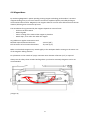
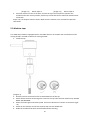
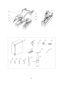
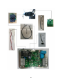
Euroboor TUBE.55S/T is a portable magnetic drilling machine designed to produce superior holes quickly and efficiently. It features a powerful motor with variable speed control, a magnetic base for secure mounting on ferrous surfaces, and a range of accessories for drilling holes in various materials. The TUBE.55S/T is ideal for use in construction, metalworking, and other industrial applications.
Euroboor TUBE.55S/T is a portable magnetic drilling machine designed to produce superior holes quickly and efficiently. It features a powerful motor with variable speed control, a magnetic base for secure mounting on ferrous surfaces, and a range of accessories for drilling holes in various materials. The TUBE.55S/T is ideal for use in construction, metalworking, and other industrial applications.


-
 1
1
-
 2
2
-
 3
3
-
 4
4
-
 5
5
-
 6
6
-
 7
7
-
 8
8
-
 9
9
-
 10
10
-
 11
11
-
 12
12
-
 13
13
-
 14
14
-
 15
15
-
 16
16
-
 17
17
-
 18
18
-
 19
19
-
 20
20
-
 21
21
-
 22
22
-
 23
23
-
 24
24
-
 25
25
-
 26
26
-
 27
27
-
 28
28
-
 29
29
-
 30
30
-
 31
31
-
 32
32
-
 33
33
-
 34
34
-
 35
35
-
 36
36
-
 37
37
-
 38
38


Euroboor TUBE.55S/T is a portable magnetic drilling machine designed to produce superior holes quickly and efficiently. It features a powerful motor with variable speed control, a magnetic base for secure mounting on ferrous surfaces, and a range of accessories for drilling holes in various materials. The TUBE.55S/T is ideal for use in construction, metalworking, and other industrial applications.
Ask a question and I''ll find the answer in the document
Finding information in a document is now easier with AI
Related papers
-
Euroboor ECO.55 Owner's manual
-
-
-
-
-
-
-
-
-
Other documents
-
DeWalt DWE1622 User manual
-
Walter ICECUT MINI Owner's manual
-
-
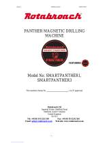 Rotabroach SMARTPANTHER1 User manual
-
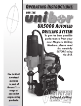 Unibor UA5000 Operating Instructions Manual
-
Metabo MAG 50 Operating instructions
-
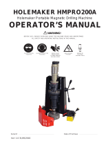 HOLEMAKER HMPRO200A User manual
-
 Nitto Kohki ATRA ACE AO-5575 User manual
-
Niigata seiki SB-60LED User manual
-
 Rotabroach Falcon RP05520/4 User manual


