Kenmore 229965530 Owner's manual
- Category
- Water heaters & boilers
- Type
- Owner's manual

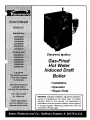
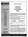
Electronic Ignition
Gas-Fired
Hot Water
Induced Draft
Boiler
• Installation
• Operation
• Repair Parts
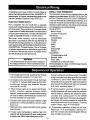
WARNING: Improper installation, adjustment, alteration,
service or maintenance can cause injury or property
damage. Refer to this manual. For assistance or
information consult a qualified installer, service agency
or the gas supplier. Natural gas boilers are not to be
converted to Propanr gas.

Warranty..........................................................2
RulesforSafe Installationand Operation.......3
BoilerRatingsand Capacities.........................4
BeforeYou Start..............................................5
Locatingtheboiler..........................................6
FreshAirforCombustion ................................7
Installation-SystemPiping.................................9
Chimney and VentPipeConnection...............11
HorizontalVenting...........................................14
Gas Supply Piping ........................................ 20
Electrical Wiring/Sequence of Operation ....... 21
Wiring Diagram ............................................. 22
Equipment and Optional Accessories - What
They Do ........................................................ 23
Checking and Adjusting ................................. 27
Maintaining "Your Boiler ................................ 28
Service Hints ................................................. 30
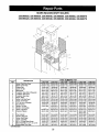
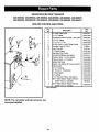
Repair Parts ................................................ 31
SEARS
KENMORE CAST IRON BOILERS
FULL ONE YEAR WARRANTY ON HOT WATER AND GAS STEAM CAST IRON BOILERS
For one (1) year from the date of installation, when this boiler is installed and maintained in accordance
with our instructions. Sears will repair defects in material or workmanship in the boiler, free of charge.
LIMITED 12 YEAR WARRANTY ON STEAM CAST IRON BOILERS
After one (1)year and thoughtwelve(12) yearfrom the dateofinstallation,Sears willfumish a replacement
heat exchange, ifthe heat exchanger inthe boilerisdefective. YOU PAYFOR LABOR.
LIMITED 20 YEAR WARRANTY ON HOT WATER CAST IRON BOILERS
After one (1) year and through twenty (20) years from the date of installation,Sears willfurnish a
replacement heat exchanger in the boilerisdefected YOU PAY FOR LABOR.
SEARS INSTALLATION WARRANTY
In addition to any warranty extended to you on the Sears merchandise involved, which warranty becomes
effective the date the merchandise is installed, should the workmanship of any Sears arranged installation
prove faulty with one year, Sears will, upon notice from you, cause such faults to be corrected at no
additional cost to you.
FOR WARRANTY SERVICE, SIMPLY CONTACT THE NEAREST SEARS STORE OR
SERVICE CENTER THROUGHOUT THE UNITED STATES. This warranty gives you specific
legal rights, and you may also have other rights which vary from state to state.
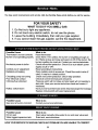
IMPORTANT
The following are the responsibilities of the user
and are cover by the Warranty.
1. Filter clearing or replacement.
2. Damage to unit or unsatisfactory operation
due to improper cleaning or use of unit in
corrosive atmosphere.
3. Damage to unit or unsatisfactory operation
due to blownfuses or inadequate or interrupted
electrical protective devices.
4. Damage to unit caused by _e use of components
or other accessoriesnot compatible with the unit:
5. If the unit is removed from the place it was
originally installed, this Warranty becomes void.
6. Damage to the unit caused by accident, abuse,
negligence, misuse, riot,fire, flood,or acts of God.
SEARS ROEBUCK AND COMPANY
D/817WA
Hoffman Estates, IL 60179
2

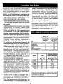
1. Readthe Owner'sManualfor SaleOperation
carefully. Failure to follow the rules for safe
operation and the instructions can cause a
malfunction of the boiler and result in death,
serious bodily in jury, and/or property damage.
2. Check your local codes and utility requirement
before installation. The installation must be in
accordance with their directives.
3. Before servicing, allow boiler to cool. Always
shut off any electricity and gas to boiler
when working on it. This will prevent any
electrical shocks or burns.
4. Never test for gas leaks with an open flame.
Use soap and check all connections. This
will avoid any possibility of fire or explosion.
5. Be certain your boiler will be using the
correct gas. Overfiring will result in
premature failure of the boiler sections and
cause dangerous operation.
6. Never vent this boiler into an enclosed
space. Always vent to the outside. Never
vent to another room or inside a building.
7. Be sure there is adequate air supply for
complete combustion.
8. Follow a regular service and maintenance
schedule for efficient and safe operation.
TOOLS
Pipe Wrench
Screwdriver
Tin Snips
6 foot tape or folding rule
Hack Saw
LP Torch, if you have copper piping
Pipe cutter and threading tools
(for iron pipe systems)
MATERIALS
Pipe joint compound suitable for natural and propane gas.
Iron or copper pipe for the water lines.
Black pipe for the gas lines.
Miscellaneous fittings.
Solder and flux if you have copper piping.
The following booklets will help you in making the installation:
Electrical Wiring -Available at Sears from the Plumbing, Heating or Electrical Departments at
nominal cost.
American National Standards, Installation of Gas Appliance and Gas Piping, National Fuel
Gas Code ANSIZ223.1 - latest revision.
Obtain from American Gas Association, 1515 Wilson Boulevard, Arlington (Roslyn), VA 22209
3

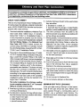
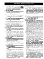
ASME
RELIEF
VALVE
I
I
I
I
I
LEFT SIDE
DRAII_
VALVE
TEMPERATURE
PRESSURE
I I I I
t I I
I I
I I I-
I I I
LiMrr & RELAY
CONTROL
Swrm_
IANIFOLD 2
23111
3 <-'--
U _tTCH
[_ _,_" INTERMnTEHT
_ILOT CONTROL
L
FRONT RIGHT SIDE
®
@
®
DESIGN CER11FIED FOR
NA_nJp_,LAND pRGPANE GA_
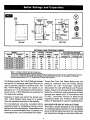
MODEL
Natural Propane
Gas Gas
229.965520 229.965320
229.965530 229.965330
229.965540 229,965340
229.965550 229.965350
229.965560 229.965369
229.965570 229,965370
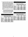
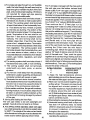
AGA Heating
NATURAL AND PROPANE GASES
Net IBR Vent Diameter(INCHES)
Rating
*MBH
31
55
82
109
135
162
Width
A
11
14¼
17%
20¾
24
27¼
To Chimney
(Category I)
4
4
4
4
4
4
No. Input
Sec. *MBH
2 42,5
3 75.0
4 112.5
5 150.0
6 167.5
7 225.0
Capacity
+MGB
36
63
94
125
155
186
Horizontal Vent
(Category III)
3
3
3
3
4
4
* MBH = 1,000 Btuh = British Thermal Unit Per Hour
Boilers are equipped foraltitudes upto 2,000 feet only: o
U.S.A. Only -For altitudes above 2,000 feet, ratings should be reduced at the rat of 4 _ for each 1,000 feet above sea level.
Canada Only - Boilers may be used at highaltitude by using a certified field conversion, kit,resulting in a 10% derate.
+ Heating Capacity based on D.O.E. (Department ofEnergy}test procedure.
The Ratings marked "Net 1=B=R Ratings" indicate
the amount of remaining heat input that can be
used to heat the radiation or terminal units. The
Net I=B=R Ratings shown are based on an
allowance of 1.15 in accordance with the factors
shown on the I=B=R Standard as published by
The Hydronics Institute.
Selection of boiler size should be based upon
"Net I=B=R Rating" being equal to or greater
than the calculated heat loss of the building.
The manufacturer should be consulted before
selecting a boiler for installations having unusual
piping and pickup requirements. These boilers must
stand on a noncombustible floor. If installed on a
combustible floor, use Combustible Floor Base.
These Gas-Fired Hot Water Boilers are low
pressure, sectional cast iron boilers Design
Certified by CSA (Canadian Standards
Association) for use with Natural and Propane
Gases. They are constructed and hydrostatically
tested for a maximum working pressure of 50psi
(pounds per square inch) in accordance with
A.S.M.E. (American Society of Mechanical
Engineers) Boiler and Pressure Vessel Code
Section IV Standards for cast iron heating boilers.
BOILERS FOR USE AT HIGH ALTITUDE
This boiler is factory equipped for use at altitudes
of 0-2,000 feet above sea level. For use at altitudes
above 2,000 feet above sea level, the input ratings
are reduced by a change in main burner orifice size.
4

Checktobesureyouhavetherightsizeboilerbefore
startinatheinstallation.Seeratingandcapacitytable
onpreviouspage.Also besurethenewboilerisfor
the type of gas you are using. Check the rating
plate onthe rightside of the boiler.
You must see that the boiler is suppliedwith the
correcttypeofgas,fresh airfor combustion,and a
suitable electrical supply. Also, the boiler must be
connected to a suitable chimney or horizontal venting
system and an adequate piping system. Finally, a
thermostat, properly located, is needed for control
of the heating system. If you have any doubts as to
the various requirements, check with localauthorities
and obtain professional help where needed. Take
the time to complete all of the steps for SAFE and
PROPER operation of the heating system.
Were required by the authority having jurisdiction,
the installation must conform toAmerican Society
of Mechanical Engineers Safety Code for Controls
and Safety Devices for Automatically Fired
Boilers, No. CSD-I*
The installation must conform to the requirements
of the authority having jurisdiction or, in the
absence of such requirements, to the National
Fuel Gas Code, ANSI Z223. l-latest revision.
The following steps are all necessary for proper
installation and safe operation of your boiler.
1. LOCATING THE BOILER
2. FRESH AIR FOR COMBUSTION
3. SYSTEM PIPING
4. CHIMNEY & VENT PIPE CONNECTION
5. GAS SUPPLY PIPING
6. ELECTRICAL WIRING
7. CHECKING &ADJUSTING
I
KEEP BOILERAREA CLEAN AND FREE FROM COMBUSTIBLE MATERIALS, GASOLINE I
AND OTHER FLAMMABLE VAPORS AND LIQUIDS
I

If your boiler is part of a planned heating system,
locate it where shown on your plan. If boiler isto
be part of an existing system, it is usually best to
put itwhere the old one was. !f you plan to change
location, you will need additional materials as well
as an adequate base. The following rules apply:
1. The boiler must be level. Metal shims may be
used under base legs for final leveling.
2. Use a raised base iffloor can become wet or damp.
3. The vent pipe connection should be as short
as possible.
4. Additional clearances for service may exceed
clearances for fire protection. Always comply
with the minimum fire protection clearances
shown on the boiler.An 18 inch clearance should
be maintained on any side where passage is
required to access another side for cleaning,
servicing, inspection or replacement of any part
that may need attention. An 18 inch clearance is
recommended on the control side for servicing.
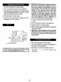
Figure 2 shows minimum clearances to
combustible construction. Rooms that are large
in comparison with the size of the boiler are
defined as rooms having a volume equal to or
greater than 16 times the volume of the boiler.
Where the actual ceiling height of a room is
greater that 8', the volume of a room shall be
figured on the basis of a ceiling height of 8'.
Determination of room size should be based
on the total volume of all gas fired equipment
installed in theroom. Consult section 6.3.1 of
the National Fuel Gas Code for further
information, including approved methodes for
reducing clearances in large room.
5. Equipment shall be installed in a location in
which the facilities for ventilation permit
satisfactory combustion of gas, proper venting,
and maintenance of ambient temperature at
safe limits under normal conditions of use.
Equipment shall be located so as not to interfere
with proper circulation of air. When normal
infiltration does not provide the necessary air,
outside air shell be introduced (See Page 4 -
"Fresh Air for Combustion").
6. Advise owner to keep air passages free of
obstructions. Ventilating and combustion air
must enter boiler room without restrictions.
7.The floor supporting the boiler must be
noncombustible. If it is combustible, place the
boiler on Combustible Floor Base No 14614031
for 2-5 section boilers, or No. 14614032 for 6-7
section boilers. We use a 2" cloudlet pad as a
combustible floor base. These are available from
your Iocalsupplier. Use 24" x 30" pad for 2-5
section boilers, and a minimum 30" x 30" pad for
6-7 sections boilers. The boiler must be centered
on the combustible floor base.
8.The boiler shall be installed such that the automatic
gas ignition system components are protected
from water (dripping, spraying, rain, etc.) during
appliance operation and service(circulator
replacement, control replacement, etc..)
Alcove, or
Room Not Large Room Large
In Comparison In Comparison
With Boiler With Boiler
Top 6" 6"
Rear 6" 6"
Control Side 8" 8"
Opposite Side 6" 6"
Front 18" 18"
FlueNent Connector 6" 6"
Near Boiler Piping 1" 1"
Minimum Room
Boiler Boiler Volume Required
Size Volume To Be Large
(Cu. Ft.) Room (Cu. Ft)*
2 sect. 4.3 68.7
3 sect. 5.6 89
4 sect. 6.8 109.3
5 sect. 8.1 129.5
6 sect. 9.4 149.8
7 sect. 10.6 170.1
I
THIS UNIT MUST BE SET ON A CONCRETE OR OTHER
NONCOMBUSTIBLE MATERIAL BASE OR FLOOR. IT MUST NOT
BE INSTALLED ON CARPETING
I
6

I Provision for combustion and ventilation air must be in accordance with Section 5.3, Air for I
Combustion and Ventilation, of the National fuel Gas Code, ANSI Z223.1-latest revision, or
I
applicable provisions of the local building codes.
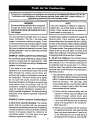
WARNING
Be sure provide enough fresh airfor combustion.
Enough air insures proper combustion and
assures that hazard will develop due to the
lack oxygen.
NOTE
If you use a fireplace or a kitchen or bathroom
exhaust fan, you should install an outside air
intake. These devices will rob the boiler and
water heater of combustion air.
You must provide for enough fresh air to assure
proper combustion. The fire in the boiler uses
oxygen. It must have a continuous supply. The air
in a house contains only enough oxygen to supply
the burner for a short time. Outside air must enter
the house to replace that used bythe burner. Study
following examples I and 2 to determine your fresh
air requirements.
EXAMPLE 1: Boiler Located in Unconfined Space
An unconfned space isdefined as a space whose
volume is not less than 50 cubic feet per 1,000
Btu per hour ofthe total input rating of allappliances
installed in that space.
If your boiler is in an open area (unpartitioned
basement) in a conventional house, the air that
leaks through the cracks around doors and
windows will usually be adequate to provide air
for combustion. The doors should not fit tightly.
Do not caulk the cracks around the windows.
Equipment located in buildings of unusually tight
construction shall be provided with air for
combustion, ventilation, and dilution of flue gases
using the methods described in example 2B or
shall be specially engineered. The authority having
jurisdiction must approve specially engineered
installations.
EXAMPLE 2: Boiler Located in Confined Space
A. All Air from Inside the Building: The confined
space shall be provided with two permanent
openings communicating directly with an additional
room(s) of sufficient volume so that the combined
volume of all spaces meets the criteria for an
unconfined space. The total input of all gas
utilization equipment installed in the
7
combined space shall be considered in making this
determination. Each opening shall have a
minimumfree area of one square inch per 1,000 Btu
per hour of the total input rating of all gas utilization
equipment in the confined space, but not less that
100 square inches. One opening shall be within 12
inches of the top and one within 12 inches of the
bottom of the enclosure. The minimum dimension of
air openings shall not be less than 3 inches.
B. All Air from Outdoors: The confined space
shall communicate with the outdoors in accordance
with methods 1 or 2. The minimum dimension of
air openings shall not be less than 3 in. Where
ducts are used, they shall be of the same cross-
sectional area as the free area of the openings to
which they connect.
1.Two permanent openings, one commencing
within 12 inches of the top, and one commencing
within 12 inches of the bottom, of the enclosure
shall be provided. The openings shall
communicate directly, or by the ducts, with the
outdoors or spaces (crawl or attic) that freely
communicate with the outdoors.
a) Where directly communicating with the
outdoors or where communicating to the
outdoors through vertical ducts, each
opening shall have a minimum free area of
1 sq. in, per 4000 Btu per hour oftotal input
rating of all equipment in the enclosure.
(See Figure 3A.)
b) Where communicating with the outdoors
throughhorizontal ducts, each opening shall
have a minimum free area of 1 area ofsq.
in. per 2000 Btu per hour of total rating of
all equipment in the enclosure. (See Fig.3B.)

2, Onepermanentopeningcommencingwith 12
inches of the top of the enclosure, shall be
permitted where the equipment has clearance
of at least 1 inch from the sides and back and
6 inches form the front of the appliance. The
opening shell directly communicate with the
outdoorsor shallcommunicate through avertical
or horizontal duct to the outdoors or spaces
(crawl or attic) that freely communicate with
the outdoors, and shall have a minimum free
area of:
a) 1 sq. inch per3000 Btu per hour ofthe total
inputofallequipment locatedinthe enclosure
(See Fig. 4), and the front of the appliance
b) Not less than the sum of the areas of all
vent connectors in the confined space.
1 Square Inch
100% Free
Area
Fresh Air 1/4, Wire
Duct Size Mesh
3" x 12" 72,000
8" x 8" 128 000
8"x 12" 192,000
81/2"x 16" 256,000
)er 2,000 Btuh
75% Free 25% Free
Area Area
Metal Wood
Louvers Louvers
54,000 18,000
96,000 32,000
144,000 48,000
192,000 64,000
1 Square Inch )er 4,000 Btuh
100% Free 75% Free 25% Free
Area Area Area
Fresh Air 1/4" Wire Metal Wood
Duct Size Mesh Louvers Louvers
3"x 12" 144,000 108,000 36,000
8" x 8" 256,000 192,000 64,000
8" x 12" 384,000 288 000 96,000
81/2" x 16" 512,000 384,000 128,000
1 Square Inch
100% Free
Area
Fresh Air 1/4" Wire
Duct Size Mesh
3" x 12" 108,000
8" x 8" 192,000
8" x 12" 288,000
81/2"x 16" 384,000
oer 3,000 Btuh
75% Free 25% Free
Area Area
Metal Wood
Louvers Louvers
81,000 27,000
144,000 48,000
216,000 72,000
288,000 96,000
8

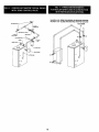
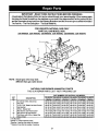
1. Place boiler in the selected location (as near
chimney as possible). Your boiler is shipped
assembled.Youneedonlyto installthecirculator,
ball valves the relief valve with a drain line to
carryanywater to adrain, andthe drain valve.
2. Install ReliefValveon 3/4"pipenippleintapped
openinginthe leftend section.Connecta drain
line of the same pipe size (3/4" to carry any
water away to a drain. No shutoff of any
descriptionshall be placed betweenthe safety
reliefvalveand theboiler,orondischargepipes
betweensuchsafetyvalvesandtheatmosphere.
Installationofthesafetyreliefvalveshallconform
to the requirements of theANSI/ASME Boiler
and PressureVessel Code,Section IV.
3. Install Drain Valve on lower left side of boiler
as marked.
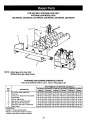
4. Connect Supply and Return Lines to boiler.
The connections may require certain
additional fittings and parts, as shown on
diagram (Figs. 5 and 6).
Ifyou are installing an entire newheatingsystem,
first install all of your radiation units (panels,
radiatorsorcabinets) and theSupplyand Return
Mains- then make the connections atthe boiler.
Inconnecting the cold water supply to the water
valve, make sure that a clean water supply is
available. When the water supply isfrom a well
or pump, a sand strainer should be installed at
the pump.
A hotwaterboiler installed above radiation level
must beequipped with a lowwater cutoff device.
Aperiodic inspection is necessary,as isflushing
of float type devices, per manufacturers specific
instructions.
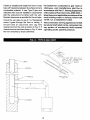
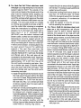
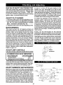
When boiler is used in connection with
refrigeration systems it shall be installed sothat
the chilled medium is piped in parallel with the
heating boiler with appropriate valves to prevent
the chilled medium from entering the heating
boiler (Fig. 7).
When this boiler isconnected to heating coils located
in air handling units where they may be exposed to
refrigerated air circulation, the piping system shall
be equipped with flow control valves or other
automatic means to prevent gravity circulation of
the boiler water during the cooling cycle.
LOW DESIGN WATER TEMPERATURE
SYSTEMS (BELOW 140 ° F)
If the boiler is to be used in a heating system
where design water temperatures below 140 °
F are desired (e.g. radiant floor heating), a 3-
way or 4-way mixing valve or suitable alternative
is required to prevent low temperature return
water from entering the boiler. Follow the mixing
valve manufacturers installation instructions.The
minimum design return water temperature to
the boiler to prevent condensation in the boiler
and venting is 120 ° F The minimum high limit
setting is 140 ° F.
9

VALVES A & B - OPEN FOR HEATING; CLOSED FOR COOLING
VALVES C & D - CLOSED FOR HEATING; OPEN FOR COOLING
TO SYSTEM
B
10

I For boilers for connection to gas vents or chimneys, vent installations shell be in accordance
with Part 7, Venting of Equipment, of the National Fuel Gas Code, ANSI Z223.l-latest issue
and applicable provisions of the local building codes.
CHECK YOUR CHIMNEY
This is a very important part of your heating system.
Itmust be clean, the right size, properly constructed
and in GOOD CONDITION. No boiler can function
properly with a bad chimney.
1. Use local codes for installation or National Fuel
Gas Code Z223.1-1atest issue. In Canada,
follow CSA 13149.1 or .2 Installation Codes. It
is very important to properly size the venting
system for induced draft appliances. Consult
the Vent Sizing Tables, in the National Fuel
Gas Code ANSI Z223.1-1atest revision for
correct sizing information In Canada, consult
the Vent Sizing Tables, Amendment #1 to CSA-
13149.1 and .2 Installation Codes.
2. The boiler's induced draft blower has a 3" outlet.
A 3" X 4" increaser fitting isincluded in the parts
bag. Locate the increaser fitting on the outlet
of the induced draft blower, and secure gastight
with a bead of the furnished silicone sealant.
The increaser fitting is required on this boiler
for Category I venting, and 4" is the minimum
permissible vent diameter. This does not imply
that the vent connector is intended to be 4"
diameter pipe. The vent connector shall be sized
according to the appropriate venting tables in
the National Fuel Gas Code or the Canadian
Installation Codes, and may be required to be
larger than 4" diameter.
The boiler installation for chimney venting
is not complete unless the 3" x 4" increaser
fitting is located and secured.
3. These are high efficiency boilers with a low stack
or exhaust temperature.
4. Ifventing into a masonry chimney without a liner,
line the chimney from top to bottom with either:
a, listed Type B vent pipe
b. listed fexible vent liner
c. poured ceramic liner.
5. Outside chimneys should not be used unless
they are either:
a. enclosed in a chase, or
b. lined with Type B vent pipe, or listed flexible
vent liner, orother certifEEI chimney lining system.
6. The vent connector from the boiler to the
chimney should run as directly as possible with
as few elbows as possible.
7. Where possible, it is recommended to common
vent the water heater and boiler. Consult the
appropriate Vent Sizing Tables in either the
National Fuel Gas Code, or the Canadian
Installation Codes for specific requirements
of multiple appliance venting.
8. If the boiler is the only appliance connected to
the vent, Type B vent pipe is recommended
for the vent connector.
9. Slope pipe up from boiler to chimney not less
than 1/4" per foot.
10. End of vent pipe must be flush with the inside
face of the chimney flue. Use a sealed-in
thimble for the chimney connection.
11. The sections of vent pipe should be fastened
with sheet metal screws to make the piping
rigid. Use stovepipe wires to support the pipe
from above.
12. Do not connect to fireplace flue.
13. Do not install a damper on this boiler.
MINIMUM VENT PIPE CLEARANCE
if the vent pipe must go through a crawl space,
Type B vent pipe should be used. Where vent
pipe passes through a combustible wall or
partition, use a ventilated metal thimble. The
thimble should be 4 inches larger in diameter than
the vent pipe.
11

If boiler is installed with single wall vent, it must
have a 6" clearance between its surface and any
combustible material. A new Type B gas vent
orflexible liner must be installed in accordance
with the instructions furnished with the vent.
Maintain clearances as specified for the vent pipe.
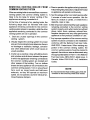
Check the vent pipe to see if it is firestopped
where it goes through the floor or ceiling. It
should have an approved vent cap with
clearances from the roof as shown in Fig. 8. If
clearances are less than shown in Fig. 8, have
the vent checked by local authorities.
For boilers for connection to gas vents or
chimneys, vent installations shall be in
accordance with Part 7, Venting Equipment,
of the national Fuel Gas Code, ANSi Z223.1-
latest issue and applicable provisions of the
local building codes. In Canada, follow CSA
13149.1 or .2 Installation Codes.
Vent connectors sewing appliances vented
by natural draft shall not be connected into
any portion of mechanical draft systems
operating under positive pressure.
m
"_- LINE R
10'_'_I Ni i
' "-J THE VENT PIPE MUST BE AT
LEAST 2 FEET HIGHER THAN
ANY PART OF THE ROOF
WITHIN A [0 FT RADIUS
OFTHE VENT,
SHEET NETAL
FIRESTO_
0 0
12

REMOVING EXISTING BOILER FROM
COMMON VENTING SYSTEM
When an existing boiler isremoved from a common
venting system, the common venting system is
likely to be too large for proper venting of the
appliances remaining connected to it.
At the time of removal of an existing boiler, the
following steps shall be followed with each
appliance remaining connected to the common
venting system placed in operation, while the other
appliance remaining connected to the common
venting system are not in operation.
1. Seal any unused openings in the common
venting system.
2. Visually inspect the venting system for proper
size and horizontal pitch and determine there is
no blockage or restriction, leakage, corrosion
and other deficiencies which could cause an
unsafe condition.
3. Insofar as is practical, close all building doors
and windows and all doors between the space
in which the appliances remaining connected to
the common venting system are located and
other spaces of the building. Turn on clothes
dryers and any appliance not connected to the
common venting system. Turn on any exhaust
fans, such as range hoods and bathroom
exhausts, so they will operate at maximum
speed. Do not operate a summer exhaust fan,
Close fireplace dampers.
4. Place in operation the appliance being inspected.
Follow the lightinginstructions. Adjust thermostat
so appliance will operate continuously.
5. Test for spillage at the hood relief opening after
5 minutes of main burner operation. Use the
flame of a match or candle, or smoke from a
cigarette, cigar or pipe.
6. After it has been determined that each appliance
remaining connected to the common venting
system properly vents when tested as outlined
above, return doors, windows, exhaust fans,
fireplace dampers and any other gas-burning
appliance to their previous conditions of use.
7. Any improper operation of the common venting
system should be corrected so the installation
conforms with the National Fuel Gas Code,
ANSI Z223.1-1atest issue. When resizing any
portion of the common venting system, the
common venting system should be resized to
approach the minimum size as determined using
the appropriate tables in Part 11 in the National
Fuel Gas Code, ANSI Z223.1-1atest issue. In
Canada, follow CSA B149.1 or.2 Installation
Codes.
NOTE
It is recommended that existing gas vents be
checked to be sure they meet local codes.
13

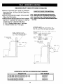
INDUCED DRAFT HIGH EFFICIENCY BOILERS
Maximum Horizontal Vent Length For Stainless
Steel Vent Pipe - 30' Plus One 90° Elbow Plus
VentTerminal
Minimum HorizontalVent Length - 2' PlusOne 90°
ElbowVent Termination
Additional elbowsare equivalentto6 feet ofstraight
pipe for 4" diameter 90° elbow or 3 feet of
straight pipe for 3° diameter 90° elbow
2, 3, 4, 5, Section Boilers use 3"vent pipe.
6, 7 Section Boilers use 4" vent pipe.
OPTIONAL TERMINATION F[TTTNG
TJERNLUNB SIDE WALL VENT HOOD
VH-I_3" FOR 2,3,4,5 SECTION BOILERS
VH-I-4' FOR 6,7 SECTION BOILERS
PER FBBT_\
CHOICE OF VENT PIPE MATERIAL
a) U.L. Listed Z-Flex Z-Vent Stainless Steel Vent Pipe.
b) UL ListedHeat-FabSat-T-VentSlainlessSteelVentPipe.
c) U.L Listed Flex-L Star-34 Stainless Steel VentPipe.
d) U.L Listed ProTech Systems FssNSeal Stainless st_eel
Vent Pipe.
TERMINATION FITTING
90" EL_OW, POINT;NO DOWN, SAME MATERIAL AN_
PIPE SIZE AS VENT[NO SYSTEM, EQUIP WITH SCREEN
(M[N. I/4" MESH) TO KEEP OUT BI_S ANB RODENTS,
FOR A COMBUSTIBLE WALL, USE A THIMBLE, SELECT Ag
FOLLOWS=
VENT RIPE; Z-VENT, SAF-T-VENT, STAR-34
THIMBLE: SIMPSON DURAVENT THIMBLE
#905295 - 3" THIMBLE
#915_95 - 4" THIMBLE
VENT PIPE_ FASNSE_L
TH[MBLD FASNSEAL WALL THIMBLE
#FSVT03 - 3" TH[MBLE
#FS_T04 - 4" THTMBLE
PITCH DOWN TOWARD
OUTSIDE I/4"
PER FOD___
HORIZONTAL VENTING ACCESSORIES PART NUMBERS
DESCRIPTION
3" side Wall Vent Hood (Tjernlund VH-1-3")
4" side Wall Vent Hood (Tjernlund VH-1-4")
3" Thimble (Simpson 905295)
4" Thimble (Simpson 915295)
PART NUMBER
146-29-010
146-29-011
146-29-013
146-29-014
14

1. These boilers may be vented horizontally as
shown in Fig. 9. The vent pipe is pitchedlml_l
from the boiler to the vent termination. Do not
connect other appliances to this vent.
2. Vent Pipe Material:
a) UL Listed Z-Flex Z-Vent stainless steel vent
pipe from boiler to vent termination,
-or-
b) UL Listed Heat-FabSaf-T-Vent stainless steel
vent pipe from boiler to vent termination,
-or-
c) UL Listed Flex-L StaR-34 stainless steel vent
pipe from boiler to vent termination,
-or-
d) UL Listed ProTech FasNSeal stainless steel
vent pipe from boiler to vent termination.
3. Clearance to Combustible Materials:
For stainless steel vent pipe maintain 6" minimum
air space clearance to combustible materials.
4. Vent Pipe Size:
a) 2, 3, 4 and 5 section boilers use 3" vent pipe
connected directly to the outlet of the induced
draft blower.
b) 6 and 7 section boilers use 4" vent pipe,
starting with a 3" to 4" stainless steel vent
pipe transition that is connected directly to
the outlet of the induced draft blower. Do not
use 3" vent pipe on 6 or7 section boilers.
5. Vent Pipe Length:
a) For stainless steel vent pipe, the maximum
horizontal vent length is 30 feet plus one 90°
elbow plus termination fitting.
b) Minimum horizontal vent length for all vent
materials is 2 feet plus one 90 ° elbow plus
termination fitting.
c) For additional elbows reduce the maximum
vent length as shown:
3"- 90° elbow -reduce ventler_glh3 feet pereach 3''
elbow,
4" - 90° elbow - reduce vent length 6 feet per
each 4" elbow.
Example: 6 section boiler requires 3 elbows
plus the termination fitting. This means 2
additional 4" elbows will be used, at 6 feet
per elbow. This is equivalent to 12 feet of
pipe (2 x 6 =12), therefore maximum vent
length is now 18 feet (30 -12 =18). 15
6. Vent Termination Fitting:
For all vent pipe materials, you may use either:
a) a 90° elbow pointing down, fitted with a
minimum 1/4" mesh screen to keep out
rodents and birds. The elbow shall be of the
same material and size as vent pipe. The
elbow exit should be at least 6" away from
exterior wall as shown in Figure 9.
-or-
b) Tjernlund VH-1 Series side wall vent hood.
For 2, 3, 4, 5 section boilers use VH-1-3", For
6, 7 section boilers use VH-1-4".
7. Vent Pipe Termination Location:
a) When venting through combustible walls,
combustible clearances must be considered.
The VH-1 Side wall vent hood provides both
the outside vent termination and a double
wall pipe for passing through a combustible
wall up to 8" thick (VH-1-4") or 9" thick (VH-
1-3"). The hole in the wall must be 6%" square
for 3" vent pipe and 7 1/2" square for 4" vent
pipe, in order to insert the VH-1 side wall
vent hood. The VH-1 may also be used in
noncombustible walls.
b) If the 90' elbow is the termination fitting of
choice, then the single wall pipe willbe passing
through the side wall. For combustible walls,
a UL listed thimble shall be used where the
single wall pipe passes through the wall. For
combustible walls using Z-Vent, Sat-T-Vent,
or StaR-34 vent pipe, use the following:
3" vent pipe - use Simpson's Duravent
#905295 3" thimble or equivalent
4" vent pipe - use Simpson's Duravent
#915295 4" thimble or equivalent Maximum
wall thickness with this thimble is 7 inches.
For combustible walls using ProTech
FasNSeal where the single wall vent pipe must
pass through the side wall, a UL Listed
FasNSeal wall thimble shall be used as
follows:
3" FasNSeal vent pipe - use 3" FasNSeal Wall
Thimble #FSWT03 4" FasNSeal vent pipe - use
4" FasNSeal Wall Thimble #FSWT04
The thimble is adjustable for different wall
thickness, with a maximum wall thickness of
7 inches. Seal the thimble along the outside
edge of the plate with caulk or silicone and
fasten to the wall with screws or nails.

c) For single wall pipe through non-combustible
walls, the hole through the wall need only be
large enough to maintain the pitch of the vent
pipe, and provide proper sealing. A thimble is
not required for single wall pipe passing
through noncombustible walls.
d) The venting system shall terminate at least 3
feet above any forced air inlet located within
10 feet. The venting system shall terminate
at least 4 feet below, 4 feet horizontally from,
or 1 foot above any door, window, or gravity
air inlet into any building. The bottom of the
vent shall be located at least 12 inches above
grade. Termination of the vent shall be not
less than 7 feet above an adjacent public
walkway. The vent terminal shall not be
installed closer than 3 feet from the inside
corner of an L shaped structure. Termination
of the vent should be kept at least 3 feet away
from vegetation. The venting system shall
terminate at least 4 feet horizontally from, and
in no case above or below, unless a 4 foot
horizontal distance is maintained, from electric
meters, gas meters, regulators, and relief
equipment,
e) The venting system shall terminate at least 4
feet below any eave, soffit, or roof overhang.
f) The venting system shall not terminate
underneath any deck, patio, or similar
structure.
g) Put vent on a wall away from the prevailing
winter wind. Locate or guard the vent to prevent
accidental contact with people or pets.
h) Terminate the vent above normal snowline.
Avoid locations where snow may drift and block
the vent. Ice or snow may cause the boiler to
shut down if the vent becomes obstructed.
i) Under certain conditions, flue gas will condense,
forming moisture. In such cases, steps should
be taken to prevent building materials at the
vent terminal from being damaged by exhaust
of flue gas.
8. Joining and Sealing the Vent Pipe:
The vent pipe needs to be both watertight and
gastight. Seal a!l joints and seams as follows:
A. For Z-Flex Z-Vent stainless steel vent pipe
use a high temperature red silicone sealant rated
for 500°F. The outside ofthe male end and inside
ofthe female end ofthe pipe must be cleaned with
brake cleaner before applying silicone bead,
16
For 3"vent pipe runs begin with the male end of
the vent pipe over the boilers induced draft
blower outlet. For 4" vent pipe runs begin with a
6" length of 3" Z-Vent (#02SVEPxx0306) over
the boiler's induced draft blower outlet, to which
an even bead of high temperature silicone sealant
should be applied. Then connect the 3" Z-Vent
to a Z-Vent 3" to 4" reducer (#02SVERxx0403).
Then continue the 4" Z-Vent pipe run by
connecting the 4" male end of the Z-Vent to the
reducer. (A locking band may be used around
this joint for additional support.) Then following
the sealing instructions, push the 4" male end of
the Z-Vent over the 4" increaser fitting. When
using the Tjernlund VH-1 vent hood, the female
end (flared end) of the vent pipe will be
connected to the termination hood. The male
end of the vent hood must be crimped before
pushing the Z-Vent over the vent hood's
connecting pipe. Before the pipes are joined,
apply a 1/4" bead of silicone one inch from the
end of themale end. Then push the pipes
together as far as they will go making sure any
seams are aligned and oriented upward. Now
apply another bead of silicone around this joint
and smooth out. Then use a Z-Flex locking band
around the center of the joint.
Z-Flex Z-Vent Size Lockina Band Part #
3" #02SVSLBX03
4" #02SVSLBX04
1) Apply the high temperature silicone
approximately one inch from the end, around
the male end of the pipe in an even 1t4" bead.
2) Pipes can now be pushed together as far
as they will go. The seams on pipe should
be aligned and oriented upward in all
horizontal appliances. Apply another bead
of silicone around this joint and smooth
out.3) Slide locking band over center ofjoint
and tighten gear clamps. Make sure locking
band is centered on joint.
4) Check alljoints and seams for gas tightness.
5) Horizontal venting shall have a slope not
less than 1/4" (6.4mm) every 12 inches
(305mm) downward away from the boiler
to prevent collection of condensate
throughout the assembly.
6)Allow the sealant to cure for 24 hours before
operating the appliance.

B. For Heat-Fab Saf-T-Vent stainless steel
vent pipe use a high temperature red silicone
sealant rated for 500"F The outside of the
male end and inside of the female end of the
pipe must be cleaned before applying the
silicone bead. For 3" vent pipe runs, the male
end of the vent pipe which goes over the outlet
of the boiler's induced draft blower must be
crimped. The vent pipe should be crimped
as minimal as possible to provide a tight fit
over the outlet. After crimping is completed
follow the instructions for applying silicone
sealant. For 4" vent pipe runs, begin with a
Saf-T-Vent 3" to 4" increaser fitting
(#7374GC) over the boiler's induced draft
blower outlet, to which an even bead of high
temperature silicone sealant should be
applied. Then continue the 4" Saf-T-Vent pipe
run by connecting the 4" male end of the Sal-
T-Vent to the increaser. (A locking band may
be used around this joint for additional
support.) The vent flow must bein the
direction indicated on the vent pipe. When
using the Tjernlund VH-1 vent hood, the female
end (flared end) of the vent pipe will be
connected to the termination hood. Apply high
temperature silicone in an even 1/4" bead
approximately 1/4" to 3/8" from the end of
the vent hood's connecting vent pipe. Also,
run a similar size bead of silicone sealant
down the seam weld of the vent pipe. Then
push the female end over the vent hood's
connecting vent pipe.
1) Apply the high temperature silicone around
the male end of the pipe (without the tabs)
in an even W' bead. Silicone bead should be
approximately 1/4" to 3/8" from the end of
the male end. Also, run a similar size bead
of silicone sealant down the seam weld at
the end of each joint.
2) Pipes can now be pushed together as far as
theywill go. The seams onthe vent pipeshould
be aligned and oriented upward in all
horizontal appliances. With a moistened finger
or fiat tool, spread any sealant that squeezes
out around the circumference of the joint.
3) Attach the sections together with the
locking rings and tabs (except at the blower
outlet where no locking ring exists.)
17
C=
Inspect the joint to ensure that flue gases
will not leak. If necessary apply additional
sealant around the joint.
4) Horizontal venting shall have a slope not
less than 114" (6.4mm) every 12 inches
(305mm) downward away from the boiler
to prevent collection of condensate
throughout the assembly.
5) Allow the sealant to cure for 24 hours
before operating the appliance.
For Flex-L StaR-34 stainless steel vent
pipe use a high temperature red silicone
sealant rated for 500°F. Before applying
silicone, the outside of the male end and
inside of the female end of the pipe must be
cleaned using a cleaner, such as methyl ethyl
ketone (MEK) or naptha. For 3" vent pipe
runs, begin with the male end of the vent pipe
over the boiler's induced draft blower outlet.
For4" vent pipe runs begin with a StaR-34 3"
to 4" increaser fitting (#SR10304) over the
boiler's induced draft blower outlet. For both
3" and 4" vent pipe runs, apply a bead of
silicone sealant around the blower outlet and
around the inside of the male end of vent
pipe going over the blower's outlet. When
using the Tjemlund VH-1 vent hood, the female
end (flared end) of the vent pipe will be
connected to the termination hood. Apply high
temperature silicone in an even %4" bead
approximately 1/4"frem the end of the vent
hood's connecting vent pipe. Also, run a similar
size bead of silicone sealant down the seam
weld of the vent pipe. Then push the female
end over the vent hood's connecting vent pipe.
Now fillin the channel inlet withsilicone sealant.
Do not try to insert the joiner band, instead
fasten the vent pipe to the vent hood's pipe
with a steel gear clamp.
1) Apply the high temperature silicone around
the male end of the pipe in an even 114"
bead. Silicone bead should be approximately
1/4" from the end of the male end. Also, run
a similar size bead of silicone sealant down
the seam weld at the end of each joint.
2) The seams on the vent pipe should be
aligned and oriented upward in all horizontal
vent pipe runs.

3) insert the male end of one into the female end
of the other. Push the pipe together so the
female end rests up against the stop bead of
the male end.
4) Insert a StaR-Joiner Band into the inlet of the
beaded channel. Feed the Joiner Band in so it
makes itsway aroundthe pipe,back to the channel
inlet and it overlaps itself by about lf2".
5) Cut the excess Joiner Band so it lays fiat in
the beaded channel. Fillthe inlet of the beaded
channel with high temperature silicone. Smooth
out the silicone over the channel inlet and the
silicone between the female end and the stop
bead of the male end.
6) Horizontal venting shall have a slope not less
than 1/4" (6.4mm) every 12 inches (305ram)
downward away from the boiler to prevent
collection of condensate throughoutthe assembly.
7) Allow the sealant to cure for 24 hours before
operating the appliance.
D. For ProTech Systems FasNSeal stainless
steel vent pipe no cleaning fluid is required.
For 3" vent pipe runs on 2, 3, 4 and 5 section
boilers begin by locating the FasNSeal Ametek
Adapter (part #FSAMETEK) over the boiler's
induced draft blower. Continue the vent pipe run
with 3" FasNSeal vent pipe. For 6 and 7 section
boilers begin by locating the FasNSeal Ametek
Adapter (part #FSAMETEK) over the boiler's
induced draft blower. Then connect a
FasNSeal 3" to 4" increaser (part #FS341 ) to
the 3" adapter outlet. Continue the vent pipe
run with 4" FasNSeal vent pipe. Other than
the Ametek Adapter and increaser fitting, DO
NOT use 3" vent pipe on 6 or7 section boilers.
FasNSeal vent pipe is joined and sealed by
the use of an internal sealing gasket and a
locking band on the female end of each vent
pipe. All components should be examined for
possible shipping damage prior to installation.
Align all vent pipe seams and orient upward in
all horizontal applications. Adjustable vent
lengths are available for 4" diameter vent
piping. For 3" diameter vent piping, square cut
male end atthe desired length. For2, 3, 4 and
5 section boilers using the VH-1-3" vent hood,
connect the FasNSeal Vent to the VH-1-3" vent
hood using FasNSeal Adapter #FSC-DUN-3.
This adapter has no internal sealing gasket.
18
To attach the adapter to the vent hood, crimp
the 3" vent hood pipe, apply a 1/4" bead of high
temperature red silicone sealant around the
outside of the vent hood's crimped connecting
pipe and a similar bead of high temperature
silicone around the inside of the FasNSeal
adapter. After pressing the two pipes together
and tightening the locking band, finish creating a
complete seal by filling the FasNSeal adapter's
notched hole with high temperature silicone.
For 6 and 7 section boilers using the VH-1 -4" vent
hood, an adapter is not required. The 4" FasNSeal
vent pipe connects directly to the VH-1-4" vent
hood, and isjoined and sealed bythe intemal gasket
and locking band.
To join and seal the FasNSeal vent pipe:
1) Insert male end into female section.
2) Push the units together as far as possible.
3) Firmly tighten locking band with a nut driver.
4) DO NOT penetrate the FasNSeal vent pipe
with fasteners.
5) Horizontalventingshallhave a slopeof notlessthan
1/4" (6.4mm),every 12 inches (305ram) downward
away from the boiler to prevent the collection of
condensate throughout the assembly.
9, Support Spacing:
Do not restrict thermal expansion movement
of the vent, The vent pipe must expand and
contract freely with temperature change. Each
run of vent piping shall be supported as
follows:
a) Z-Flex stainless steel vent piping requires
a loose fitting metal strap or similar support
at each joint at a maximum of 4 feet
between supports.
b) Heat-Fab stainless steel vent piping requires
a support for every 6 feet of horizontal piping
run. The support must be secured using at
least #10 fasteners to a solid material (solid
masonry or woodframing or blocking.) Do
not fasten to drywall sheathing using hollow
wall anchors. Each support will be 1 1/2 inch
lower than the previous support when
spaced 6 feet apart.
c) Flex-L stainless steel vent piping requires
a loose fitting metal strap or similar support
at each joint at a maximum of 4 feet
between supports.

d) ProTech stainless steel vent piping requires
one loose fitting FasNSeal support strap
(#FSSH) for every 6' of horizontal vent.
10. If the horizontal vent must go th rough a crawl
space or other unheated space, the cool
temperatures will likely cause the flue gases
to continuously condense inside the vent pipe.
Do not insulate the vent pipe. It must be visible
for monthly inspection. Insure that the vent
pipe is properly pitched away from the boiler,
with no low spots, so that condensate in the
vent will drain away from the boiler. An insulated
enclosure or chase, with access for inspection
and servicing of the vent, may be required to
prevent freezing of liquid condensate. Consult
the vent pipe manufacturer's instructions for
specific guidelines.
11. At the beginning of each heating season and
monthly during the heating season, check all
vent pipes and the vent terminal to make sure
there are no obstructions. Periodically clean
the screen in the vent terminal.
Horizontal venting with a power venter is an
alternate method of sidewall venting. This boilers
CSA listed for sidewall venting with standard
single wall galvanized or Type B vent pipe when
using the following power venter kits, which were
specifically sized for these boilers:
Number of
Boiler Sections Kit
2,3,4,5
6,7
Field Controls
Power Venter
SWG-4D
SWG-5D
Some possible reasons for using a power venter
for sidewall venting:
1. May be preferred by local codes.
2. Need a vent piping run beyond 30' (but
not more than 50').
3. The boiler installation site experiences
gusting or high winds. A power venter can
help prevent the boiler from short cycling
due to gusting or high winds by providing
vent exhaust pressures greater than the
boiler's induced draft blower alone.
4. When installers or homeowner's prefer a
negative pressure vent system instead of
a positive pressure vent system.
5. May be more cost effective than stainless
steel venting, particularly at longer vent
lengths.
The Field Controls power vent kit includes either
a SWG-II-4HD or SWG-II-5 power venter, a
MG-1 4" barometric draft controller, and the
CK-43D controls kit.
Confirm that installing a power venter is an option
allowed by local codes. Follow the specific power
venter installation instructions issued with the
power venter kits. Although the power venter is
equipped with its own fan, the fan on the boiler
remains in place and is unaltered when a power
venter is used. When sidewall venting, flue gases
must be vented to a point in relation to the
prevailing wind so that they may freely disperse
without being blown back at the building causing
discoloration, or into the building through doors
or windows causing odors. Also, under certain
conditions flue gases will condense, forming
moisture. In such cases, steps should be taken
to prevent building materials at the vent terminal
from being damaged by the exhausted flue gas.
When installing single wall galvanized vent pipe
for power venting follow the specific power
venter installation instructions for layout, location
of the barometric draft control and termination
connections. When joining and sealing the single
wall galvanized or Type B vent piping, use R-IV
silicone sealant with a minimum temperature
rating of 400°F. For 3" vent pipe runs, begin with
the female end of the vent pipe over the boiler's
induced draft blower outlet. For 4" vent pipe runs
begin with the galvanized 3" to 4" increaser fitting
(included in the boiler's parts bag) over the
induced draft blower outlet. Then follow by
placing the female end of the 4" vent pipe over
the increaser fitting. When joining pieces of single
wall galvanized vent pipe, a substantial bead of
silicone should be used at the joint to insure a
leakproof connection.
19

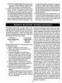
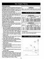
CHECKGAS SUPPLY
The gaspipe toyour boiler must bethe corrects'[zefor the
lengthofthe runand forthetotal BTU perhour inputofall
gas utilization equipment connected to it.See F_J.10 for
the proper size. Be sure your gas linecomplies with local
codes and gas company requirements.
The boiler and its individual shutoff vaive must be
disconnected from the gas supply piping system during
any pressure testing of thatsystem at test pressures in
excess of 1/2 psig (3.5 kPa).
The boiler must be isolated from the gas supply piping
system bydosing itsindividualmanualshutoffvak_during
any pressure testing of the gas supply piping system at
test pressures equal to or less than 1/2 psig (3.5 kPa).
CONNECTING THE GAS PIPING
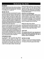
Refer to Fig, 11 for the general layout at the boiler. It
showsthe basic f-_ngs youwill need. The gas lineenters
the boiler from the right side.
following rules apply:
1.Use only those piping materials and joining metheds
listed as acceptable bythe authority having jurisd_on,
or inthe absence ofsuch requirements, bythe Nationel
Fuel Gas Code, ANSI ZX223.1-1atest revision. In
Canada, follow the CSA B149.1 and .2 Installation
Codes for Gas Burning Appliances and Equipment
2. All pipe compound must be resistant to liquefied
pe'm3leumgas.
3. Install ground joint union in gas supply line between
shut-off valve and boiler controls.
4. Install a sediment Imp upskeam of gas controls.
5. Use two pipewrenches when making the conneclJon
to the gas valve to keep itfrom turning.
6. Install manual shut-off valve in ver'dcal pipe about 5
feet above floor.
7. rKjhten all joints securely.
8. Propane gas conneclions should only be made by a
licensed propane installer.
9.Two-stage regulation should be used bythe propane
installer.
10. Propane gas piping should be checked out by the
propane installer.
CHECKING THE GAS PIPING
Upon completion of piping, check rightaway for gas
leaks. Open the manual shut-off valve. Test for leaks
by applying soap suds (or a liquid detergent) to each
joint. Bubbles forming indicate a leak. CORRECT
EVEN THE SMALLEST LEAK AT ONCE.
2O
I WARNING I
Never use a match or open flam to test for leaks.
Length of
Pipe - Ft.
20
40
60
NATURAL GAS
Pipe Capacity - BTU Per Hour Input
Includes Fittings
1/2" 3/4" 1" 1 1/4"
92,000 190,000 350,000 625,000
63,000 130,000 245,000 445,000
50,000 105,000 195,000 365,000
PROPANE GAS
Pipe Capacity - BTU Per Hour Input
Length of Includes Fittings
Pipe - Ft. Copper Tubin@* Iron Pipe
5/8" 3/4" 1/2" 3/4!'
20 131,000 216,000 189,000 393,000
40 90,000 145,000 129,000 267,000
60 72,000 121,000 103,000 217,000
*Outside diameter
The length of pipe or tubing should be measured from the
gas meter or propane second stage regulator,
FLOOR LINE
Page is loading ...
Page is loading ...
Page is loading ...
Page is loading ...
Page is loading ...
Page is loading ...
Page is loading ...
Page is loading ...
Page is loading ...
Page is loading ...
Page is loading ...
Page is loading ...
Page is loading ...
Page is loading ...
Page is loading ...
Page is loading ...
-
 1
1
-
 2
2
-
 3
3
-
 4
4
-
 5
5
-
 6
6
-
 7
7
-
 8
8
-
 9
9
-
 10
10
-
 11
11
-
 12
12
-
 13
13
-
 14
14
-
 15
15
-
 16
16
-
 17
17
-
 18
18
-
 19
19
-
 20
20
-
 21
21
-
 22
22
-
 23
23
-
 24
24
-
 25
25
-
 26
26
-
 27
27
-
 28
28
-
 29
29
-
 30
30
-
 31
31
-
 32
32
-
 33
33
-
 34
34
-
 35
35
-
 36
36


Kenmore 229965530 Owner's manual
- Category
- Water heaters & boilers
- Type
- Owner's manual
Ask a question and I''ll find the answer in the document
Finding information in a document is now easier with AI
Related papers
Other documents
-
 RackBuddy Logan Operating instructions
-
 T & S Brass & Bronze Works B-1027 Datasheet
-
Columbia CDVB SERIES Installation, Operation & Maintanance Manual
-
-
-
U.S. Boiler Company INDEPENDENCE IN4PV Installation & Operating Manual
-
Crown Boiler BSI138ENPZZPSU Installation guide
-
Lennox BWB Owner's manual
-
Dunkirk PWB IOM Installation & Operation Manual
-
Dunkirk XEB Series II Installation & Operation Manual

