Page is loading ...

CONTRO-E
OWNER’S MANUAL SUPPLEMENT
CANNONDALE EUROPE
Cycling Sports Group Europe, B.V.
Hanzepoort 27, 7570 GC, Oldenzaal,
Netherlands
(Voice): +41 61 4879380
(Fax): +31 5415 14240
CANNONDALE UK
Cycling Sports Group
Vantage Way, The Fulcrum,
Poole, Dorset, BH12 4NU
(Voice): +44 (0)1202 732288
(Fax): +44 (0)1202 723366
Warning! Read this supplement and your cannondale bicycle owner’s manual.
Both contain important safety information. Keep both for future reference.
WWW.CANNONDALE.COM
© 2015 Cycling Sports Group
133082 (04/15)
133082
CONTRO-E
OWNER’S MANUAL SUPPLEMENT
A DIVISION OF
133082 CONTROE OMS COVER 0415.indd 1 23.04.15 17:17

1
133082 (04/15)
Cannondale Supplements
This manual is a “supplement” to your Cannondale
Bicycle Owner’s Manual. This supplement provides
additional and important model specific safety,
maintenance, and technical information. It may be
one of several important manuals/supplements for
your bike; obtain and read all of them.
Please contact your Cannondale Dealer immediately
if you need a manual or supplement, or have a
question about your bike. You may also contact
us using the appropriate country/region/location
information. See Contacting Cannondale in this
supplement.
You can download Adobe Acrobat PDF versions of
any manual/supplement from our website:
www.cannondale.com
This supplement contains information for the
following models:
MODEL CODE MODEL DESCRIPTION COMPLIANCE
CM2491SM01 CONTRO-e HS 26”
BOSCH
CM2491MD01 CONTRO-e HS 26”
CM2491LG01 CONTRO-e HS 26”
CM2490MD01 CONTRO-e Rigid 24”
CM2490LG01 CONTRO-e Rigid 24”
C62216M1002 CONTRO-e Rigid US 24”
C62216M1003 CONTRO-e Rigid US 24”
Contents
SAFETY INFORMATION ............................................................2-3
PARTS OF THE E-SERIES BIKE ....................................................4
LEFTY RIGID FRONT WHEEL ....................................................... 5
MAINTENANCE / CLEANING / TORQUE ................................ 6-7
GEOMETRY / SPECIFICATIONS ....................................................8
REPLACEMENT PARTS..................................................................9
Explicit Denitions
In this supplement, particularly important
information is presented in the following ways:
WARNING
Indicates a hazardous situation which, if not
avoided, could result in death or serious injury.
NOTICE
Indicates special precautions that must be taken
to avoid damage.
BOSCH eBike Manuals
The manufacturer’s owner’s manuals and
instructions for the operation and maintenance of
the drive-assist system are available as electronic
downloads (in Adobe Acrobat PDF format) from our
website.Obtain and read these materials BEFORE you
operate the bike.
Go to : http://www.bosch-ebike.de
Contacting Cannondale
Cycling Sports Group Europe B.V
Mail: Postbus 5100
Visits: Hanzepoort 27
7570 GC, OLDENZAAL, Netherlands
Tel: +41 61 4879380
Fax: +31 5415 14240
This bike complies with EN 15194.
EN14764 - Electrically Power
Assisted Cycles (EPAC).
EN

2
safety InformatIon
Intended Use
Your E-Series bike has an electric pedal assist drive system. It is not a
moped or motorcycle. In EU countries, it is known legally as an “EPAC”
cycle or Electrically Powered Assisted Cycle.
The drive assist system consists of a drive unit, a battery, a computer
control, and various electronic components (harness wires, sensors, and
switches). Your E-Series bike does share components common with
pedal only bikes.
It is important to know that when the assist system is turned ON, the
drive unit engages to provide power only while you are pedaling. The
amount of power provided by the drive unit depends on your pedaling
force and the assistance mode/level you set with the handlebar control
unit. At anytime, if you stop pedaling, the drive assist will disengage.
In all modes/levels, the drive assist system power reduces progressively
and cuts off as the bike reaches a speed of 25 km/h, (15.5 mph), or
sooner if you stop pedaling. The drive assist re-engages when speed
drops below 25 km/h, (15.5 mph) as long as the pedals are turning.
Whenever the drive assist system is turned OFF, You can pedal the bike
normally. The drive system will not engage.
CONTRO-E
ASTM CONDITION 2,
General Purpose
Riding
INTENDED:For paved roads, gravel or dirt
roads that are in good condition, and bike
paths.
NOT INTENDED: For off-road or mountain
bike use, or for any kind of jumping.
Maximum Weight Limit (Lbs/Kg)
RIDER LUGAGE TOTAL
300/136 55/25 330/150
WARNING
**INTENDED USE: This bicycle is intended to be used as a
commuter bicycle. This bike complies with the requirements of
European Standard EN 15194, Electrically Power Assisted Cycles.
The drive assist system is limited to a maximum continuous
power rating of 0,25 kW (250 W) and a maximum speed of
25Km/h, (15.5 mph).
NOT INTENDED: You must not ride this bike in automobile
traffic lanes. This vehicle must only be operated on paved
surfaces that are legally open to commuter pedal bicycles. This
bike is not for mountain biking use, jumping, or racing.
YOU MUST FOLLOW ALL LOCAL LAWS: It is your responsibility
to identify and follow all local laws and regulations (including
fitting your bike with additional equipment) necessary to
comply with local laws. Ask your Cannondale Dealer for more
information about operating an electrically assisted pedal
bicycle in your area.
DO NOT MODIFY THIS BICYCLE/FORK IN ANY WAY FOR ANY
REASON. Doing so can result in severe damage, faulty or
dangerous operating conditions, or violation of local laws.
IMPORTANCE OF PRACTICE & RIDER TRAINING - Before you
ride this bike, practice riding in a safe area free from hazards.
Take time to learn to bike’s controls and performance. Practice
the controls and gain the experience necessary to avoid the
many hazards you will encounter while riding.
DO NOT RIDE “HANDS-OFF - Keep you hands on and the
handlebars when riding the bike. If you remove your hands
from the handlebar while riding, you can lose control of the
bicycle and crash.
UNDERSTAND YOUR BIKE AND ITS INTENDED USE. USING
YOUR BIKE THE WRONG WAY IS DANGEROUS.
Please read your Cannondale Bicycle Owner’s Manual for more
information about Intended Use and Conditions 1-5.
YOU CAN BE YOU SERIOUSLY INJURED, PARALYZED OR KILLED
IF YOU IGNORE THESE WARNINGS.

3
Read the Drive System
Manufacturer’s Instructions
WARNING
MANUFACTURER’S INSTRUCTIONS -In addition to this
supplement, you must read and follow the manufacturer’s
instructions for all components of the drive assist system. These
instructions contain correct operation, service and maintenance
information. More information please visit: http://www.
cannondale.com/manual_ebikes/.
LEFTY Rigid Front Wheel
WARNING
■ DO NOT CONTAMINATE BRAKE CALIPER, PADS, OR ROTOR
WITH GREASE.
■ DO NOT RIDE WITHOUT A PROPERLY MOUNTED, ADJUSTED,
AND FUNCTIONING FRONT BRAKE SYSTEM. The Lefty (disc/
caliper) acts as an integral secondary wheel retention system.
If the system is missing or improperly installed, or if the wheel
hub axle bolt should loosen, the front wheel could slide off the
spindle end.
When mounting IS compatible brake systems:
Follow brake manufacturer’s instructions when mounting the
brake caliper to the spindle brake bosses. Do not modify the
fork in any way. PLEASE ASK YOUR CANNONDALE DEALER
FOR HELP WHEN INSTALLING COMPATIBLE FRONT BRAKE
SYSTEMS.
NOTICE
■ LOCATE BRAKE ROTOR BETWEEN THE PADS. Replace
shims that are in use, be sure the shims are positioned
between the caliper (adapter if any) and inner face of
the fork mounts, not under the head of the caliper bolts.
■ USE ONLY THE LEFTY 16mm CALIPER BOLTS TO MOUNT
THE BRAKE. Longer bolts can result in contact with the
brake rotor causing severe damage. Check clearance
between the bolt tips and rotor after remounting the
caliper. Order replacement bolts - Cannondale p/n
LEFTYBOLTS.
Rear Rack & Kickstand
WARNING
Do not sit on the bicycle with the kickstand down. Kickstand
is not designed to support the weight of a person. Make sure
kickstand is up before riding.
Do not overload the rear rack. Make sure the cargo is secured
properly.
RACK MAXIMUM WEIGHT LIMIT: 25Kg, 55lbs
YOU CAN BE YOU SERIOUSLY INJURED, PARALYZED OR KILLED IF
YOU IGNORE THESE WARNINGS.
No Modication
WARNING
DO NOT ALTER, CHANGE, OR MODIFY THE BICYCLE OR THE
DRIVE ASSIST SYSTEM. Dealers and owners MUST NOT change,
alter, or modify in any way the original components of the
bicycle or drive assist system. Specifically attempts to “hot-rod”
or “improve” the speed of the bike are dangerous to the rider.
Use only specified CANNONDALE and manufacturer drive assist
service and replacement parts.
YOU CAN BE YOU SERIOUSLY INJURED, PARALYZED OR KILLED IF
YOU IGNORE THESE WARNINGS.
EN

4
4
2
5
5
11
4
12
13
7
10
1
3
8
6
13
2
12
1
3
8
9
CONTRO-E
w/LEFTY rigid
CONTRO-E
w/Headshok
Parts of tHe e-serIes
1 Drive Assist Display
2 Drive motor
3 Drive Control
4 Sensor/Spoke magnet
5 Battery
6 HEADSHOK fork
7 LEFTY Wheel Hub
8 Bell
9 Headlamp
10 LEFTY Rigid
11 Rack
12 Folding Lock
13 Kickstand
EN

5
3
1
Lefty rIGID
2
3
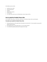
Wheel Removal
1. See Figure 1. Use a 5 mm Allen key to loosen the brake caliper
mounting bolts enought to remove the brake caliper from the
mounting tabs.
Note brake alignment shims between brake bosses and the
caliper. Replace correctly during reinstallation.
2. See Figure 2. Insert a 5 mm Allen key into the axle hub bolt and
turn the the hub extraction bolt counter-clockwise.
Continue turning the extraction bolt until the wheel can be
removed easily from the spindle end. See Figure 3.
NOTICE
■ Make sure the axle bolt is completely disengaged before
attempting to remove the wheel. Never try to pull the
wheel off forcefully.
■ When the wheel is off, to keep dirt out, cover the hub
opening.
■ Protect spindle from damage when wheel is removed.
Wheel Installation
1. Inspect inside the wheel hub for contamination and the
condition of the hub seal. Take corrective action if necessary.
Wipe the spindle clean with a dry shop towel.
Apply a high-quality bike grease to I.D. of the bearings inside
the hub.
2. Slide the wheel straight onto the spindle.
3. Turn the axle bolt clockwise to engage the spindle threads.
Make sure the wheel and spindle are supported while tightening
the hub bolt.
4. Once the hub has been drawn onto the hub completely, use
torque wrench to tighten to final 15.0 N
.
m (133.0 In
.
Lbs).
5. Reinstall the brake caliper. Tighten bolts to 78.0 In
.
Lbf
(9.0 N
.
m).
6. Spin the wheel to make sure it moves freely. Be sure to test
the brakes for proper operation before riding.

6
The following table lists only supplemental maintenance items. Please consult your Cannondale Bicycle Owner’s Manual for more
information on basic bike maintenance. Consult with your Cannondale Dealer to create a complete maintenance program for your riding
style, components, and conditions of use. Follow the maintenance recommendations given by the component manufacturer’s for the
various non-Cannondale parts of your bike.
CHECK THE FOLLOWING BEFORE EACH RIDE:
• Make sure the battery is fully charged and locked securely in position on the bicycle.
• Check tire pressure and wheel condition. Make sure wheel quick release are firmly closed.
• Check the drive chain condition. Make sure it is clean and well-lubricated.
• Check the bicycle front and rear lighting to make sure it works properly.
• Check the bicycle brakes, make sure they are working well.
• Check the function of the brakelight by pulling brake lever one after another.
• Check the function of the number plate light and make sure it works properly.
• Inspect condition of electrical cables (i.e. Kinks free, no signs of abrasive wear)
• Test the drive assist system, make sure the drive system functions normally.
• LEFTY RIGID - Check the fork for signs of damage (bending, cracking, dents, or deep scratches).
• IF YOU FIND ANY DAMAGE, DO NOT RIDE THE BIKE, CONTACT YOUR CANNONDALE DEALER.
TO BE PERFORMED BY CANNONDALE DEALER :
Recommended after the first 150 km, bring your bike to your Cannondale Dealer for an initial check-up. It should include checks of
the drive assist system, drive chain condition, proper shifting, accessories, wheels and tire condition, brakes, etc. This visit will help you
establish a schedule for repeated visits appropriate for how and where you ride.
Every 1000 km, bring your bike in to your Cannondale Dealer for a regular detailed inspection, adjustment, and replacement of wear
items across the entire bike. Electrically powered assist cycle (electric bikes) can wear out wheels, tires, drive chain, brakes, more quickly.
maIntenanCe
WARNING
ANY PART OF A POORLY MAINTAINED BIKE CAN BREAK OR MALFUNCTION LEADING TO AN ACCIDENT WHERE YOU CAN BE KILLED,
SEVERELY INJURED OR PARALYZED. Please ask your Cannondale Dealer to help you develop a complete maintenance program, a program
which includes a list of the parts on your bike for YOU to check regularly. Frequent checks are necessary to identify the problems that can
lead to an accident.

7
Cleaning
When cleaning your bike, use a damp sponge or a soft brush with only a mild soap and water solution. Rinse the sponge often. Do not spray
water.
NOTICE
Do not use a pressure washer or dry with compressed air. This will force contaminants into sealed areas, electrical connections/
components promoting corrosion, immediately damaging, or result in accelerated wear.
WARNING
KEEP WATER AWAY FROM THE ELECTRICAL COMPONENTS.
MAKE SURE THE BIKE IS SECURED UPRIGHT AND CAN NOT FALL OVER ACCIDENTALLY WHILE YOU ARE CLEANING IT. Don’t rely on the
kickstand. Use a sturdy portable bicycle wheel stand to hold the bike upright.
Tightening Torques
Correct tightening torque for the fasteners (bolts, screws, nuts) on your bicycle is very important to your safety.the durability and performance of
your bicycle. We urge you to have your Dealer correctly torque all fasteners using a torque wrench.
DESCRIPTION Nm In Lbs Loctite™
KICKSTAND MOUNTING 7.0 62.0
242 (blue)
REAR RACK MOUNTING BOLTS 3 - 4 26.5 - 35.4
STEM/HANDLEBAR CLAMP BOLTS 6.0 53.0
DROPOUT MOUNTING BOLTS 15 133
LEFTY CLAMP BOLTS 7-9 62-80
LEFTY WHEEL AXLE BOLT 15 133
If you decide to tighten fasteners yourself always use a good torque wrench!
Drive Unit
NOTICE
Drive unit is maintenance-free and must only be serviced at an authorized service center. This will ensure the quality and safety of
the driving unit. Never attempt to open, remove it from the frame, or work on it yourself. Other components of the eBike drive (e.g.
drive chain, front chain ring, rear cassette, rear derailleur, crankarm) must be serviced by your Cannondale Dealer. Replacement parts
must be identical to the original Cannondale specification for the bike. See Specifications. Failure to replace components with original
specification can result in serious overload or other damage to the drive unit. Unauthorized opening or service of the drive unit will void
the warranty. The drive system will not function without the computer unit attached to the base properly. If the computer disconnects
from the base during operation, the drive system will shut off. If this happens you will have to stop the bike, turn the system off , re-
attach the computer to the base, and then turn the system back on to resume. Remove the computer when not operating the bike to
prevent theft or unauthorized use.
EN

8
K
F
G
A
H
I J
D
L
C
B
M
E
SERIAL
MODEL
Size
(mm) A B C D E F G H I J K L M
CONTRO-E
HEADSHOK 26”
S 460 578
71° 73°
160 1085 634 456 53 287.5
4,5
79,1 641,6
M 510 598
71° 73° 160
1105 654 456 53 287.5
4,5
59,1 642
L 560 628
71° 73° 160
1135 684 456 53 287.5
4,5
59,1 642
CONTRO-E
LEFTY RIGID 24”
M 480 588 71° 73° 160 1085.22 650.62 436 27 291 4,5 59,1 616
L 540 618 71° 73° 160 1115 681 436 27 291 4,5 59,1 616
Geometry
A - Seat Tube Length
B - Top Tube Horizontal
C - Head Tube Angle
D - Seat Tube Angle
E - Head Tube Length
F - Wheelbase
G - Front Center
H - Chain Stay Length
I - Bottom Bracket Drop
J - Bottom Bracket Height
K- Fork Rake
L - Stack
M - Reach
Your E-Series bike comes with a main key and spare key. The keys are identified by the serial number SERIAL. Please record the key serial
number for future use and key replacement. If your keys are ever lost or stolen, or you would like additonal spares, please contact:
Replacement information by key manufacturer:
http://www.axa-stenman.com
www.abus.com
http://www.trelock.de/web/en/services/
schluesselservice/schluesselservice.php
NOTICE
Don’t ride with key in battery lock. Always remove the key from the
lock after using it. Keys may be stolen or break off accidentally in the
lock. Keep your spare key in a safe place. (
Record SERIAL here.
Keys

9
SI STEM
KP358/
KA055/26 (FATTY)
KA055/24 (LEFTY)
Fixed
RD
DROPOUTS
B
A
C
D
E
FRAME/RACK/KICKSTAND
KA056/ KICKSTAND CDALE SI BLK 40mm Mount Plate
KP358/ KIT RACK CONTRO BLK
KA058/ PLUGS, RACK ORTLIEB QL3 --For 26” and 24”
FORKS
HF15LARIG/24/BBQ FORK 15 LEFTY AL RIGID E-CONTRO 24 BBQ
HF15LARIG/26/BLK FORK 15 FATTY DL50-DISC 26 E-CONTRO BLK
HF15LARIG/24/BBQ FORK 15 LEFTY AL RIGID E-CONTRO 24 BBQ
DROPOUT KITS
KP356/ DROPOUT KIT (Fixed )
KP357/ DROPOUT KIT (Rear Derailleur)
DROUPOUT KIT (fixed) contains A, B, C D
DROUPOUT KIT (rear derailleur) contains A, B, C, E
FENDER
KP358/26 FENDER SET E-CONTRO 26” - HEADSHOK
KP358/24 FENDER SET E-CONTRO 24” - LEFTY RIGID
SI STEM
BIKE SIZE S M L
HEADSHOK - 26”
stem length:
KA057/S
100mm
KA057/
135mm
KA057/
135mm
LEFTY RIGID - 24”
stem length:
KA063/S
100mm
KA063/S
135mm
KA058/
KA058/
rePLaCement Parts
EN

10
sI ConsoLe
???
6 Nm, 53InLbs
4
2
6 Nm, 53InLbs
2
15 Nm, 133InLbs
5
2
5 Nm, 44InLbs
4
2
1.
2.
2.
3.
4.
4
Handlebar Adjustment
The handlebar height is adjusted by loosening the pivot bolt (1) and
moving the arms (2) handlebar up or down to the desired position.
Re-tighten the pivot bolt to the specified torque with a torque wrench
following adjustment. The adjustment bolt is treated with a thread
locking agent, but it will require periodic re-application of Loctite
#242 (blue), especially if frequent adjustments are made.
WARNING
ADJUSTMENTS SHOULD ONLY BE PERFORMED BY A QUALIFIED
BICYCLE MECHANIC.
Head Lamp & Display Mounting
The drive assist system display and head lamp and reflector brackets
are to be mounted onto the center support (3). This support will
rotate so that the mounted parts can be positioned correctly. The
head lamp mounting bracket (4) can also be rotated if necessary.
= Loctite 242 (blue)
2

CONTRO-E
OWNER’S MANUAL SUPPLEMENT
CANNONDALE EUROPE
Cycling Sports Group Europe, B.V.
Hanzepoort 27, 7570 GC, Oldenzaal,
Netherlands
(Voice): +41 61 4879380
(Fax): +31 5415 14240
CANNONDALE UK
Cycling Sports Group
Vantage Way, The Fulcrum,
Poole, Dorset, BH12 4NU
(Voice): +44 (0)1202 732288
(Fax): +44 (0)1202 723366
Warning! Read this supplement and your cannondale bicycle owner’s manual.
Both contain important safety information. Keep both for future reference.
WWW.CANNONDALE.COM
© 2015 Cycling Sports Group
133082 (04/15)
133082
CONTRO-E
OWNER’S MANUAL SUPPLEMENT
A DIVISION OF
133082 CONTROE OMS COVER 0415.indd 1 23.04.15 17:17
/