Unbranded B5SM Installation guide
- Category
- Space heaters
- Type
- Installation guide
This manual is also suitable for

APPLICATION INFORMATION
1. Follow the procedure given on the reverse side of this sheet to find
the minimum air velocity for safe operation. At least this minimum velocity
must be provided at all points over the heater face area. Failure to meet
this requirement may result in serious damage or nuisance thermal cutout
tripping.
2. The maximum air inlet temperature for open coil heaters is 100° F,
and for finned tubular heaters, 80° F.
3. The heater must be located at least 48” from any grills, registers, fil-
ters, abrupt duct size changes, humidifiers, air conditioning or air handling
units, or any other change or obstructions in the duct which may result in
nonuniform airflow. Duct elbows or turns must be located at least 4’ from
the inlet of the heater and 2’ from the outlet of the heater. Sufficient work-
ing space must be provided per paragraph 110-26 of the NEC.
4. These duct heaters are not intended for installation in series in the
airstream; the heaters are designed for use only as a single unit within a
duct with the exception of Series ZUA, XUA, TFZUA, TFLZUA, TFXUA and
TFLXUA, which are designed for stacked installation for use as a single
unit within a duct. (See Fig. No. 3)
MECHANICAL INSTALLATION
1. Heater terminal outlet box should not be enclosed. Heaters with ex-
panded metal terminal box covers must be installed in a position where air
passing out of the terminal box does not enter into confined areas of the
building structure (such as a space behind a false ceiling, a hollow space
in a wall, etc.).
2. All heaters are suitable for installation with zero spacing between the
duct and combustible surfaces.
3. The heater must be installed in the correct position as shown by the
arrows in the terminal box.
4. Sufficient clearance for convection cooling must be allowed for all
heaters with built-in INDEECO Controls Power Controllers. Provide at least
5 inches of free air space above and below cooling fins extending from
heater terminal box.
5. The air duct should be installed in accordance with the standards of
the National Fire Protection Association for installation of air conditioning
and ventilating systems of other than residence type (Pamphlet No. 90A)
and residence type warm air heating and air conditioning systems (Pam-
phlet No. 90B).
6. For proper operation of heaters equipped with a built-in airflow switch,
a minimum of .07” WC of static pressure is required in the duct system and
the velocity pickup tube for the airflow switch must be pointed in the proper
direction. When the heater is installed on the downstream or positive pres-
sure side of the air moving fan, the arrow on the mounting flange of the
pickup tube must point in the same direction as the airflow. When the
heater is installed on the upstream or negative pressure side of the air
moving fan, the arrow must point in the direction opposite to the airflow. If
incorrectly installed, remove the two screws holding the pickup tube in place,
rotate 180° and reinstall. See separate instruction sheet for installation of
heaters supplied with a remote pickup tube.
FOR FLANGE TYPE HEATERS ONLY: (See Fig. No. 1)
7. Provide flanges on the duct to match the heater flanges, both on the
entering and leaving air sides.
8. Attach the duct flanges to the heater flanges with bolts, sheet metal
screws or slip and drive connectors when the heater has matching con-
nectors for this purpose.
FOR SLIP-IN TYPE HEATERS ONLY: (See Fig. No. 2)
9. Cut a hole in the side of the duct to accommodate the body of the
heater (excluding terminal box). This hole should be 1/8” larger than the
heater frame.
10. Slip the heater into the duct and attach the back of the terminal box to
the duct with sheet metal screws.
FOR STACKED TYPE HEATERS ONLY: (See Fig. No. 3)
11. The heaters with catalog prefix ZUA, XUA, TFZUA, TFLZUA, TFXUA
or TFLXUA must be stacked as indicated in Fig. No. 3.
FOR HEATERS TO BE INSTALLED IN FIBER GLASS DUCTS:
12. Write factory for special instructions. Note that the fiber glass duct
material itself must be UL listed.
FOR HEATERS TO BE INSTALLED IN INTERIOR INSULATED DUCTS:
13. All slip-in type heaters are suitable for installation in ducts with up to
1” of interior insulation as long as they have been sized for the dimensions
inside the insulation. The heaters are not suitable for insulation depths of
greater than 1” unless a special construction has been ordered. Flange
type heaters are only suitable for installation in insulated ducts if specially
ordered for this application.
ELECTRICAL INSTALLATION
14. Follow the wiring diagram on the inside of the terminal box.
15. Supply connections must be made with copper wiring rated for 75° C
minimum. Use aluminum wire only when specifically called for on accom-
panying wiring diagram.
16. If supply connections are for 250 volts or greater, all wiring must be
insulated for 600 volts.
17. When making line connections to heater element terminals FOR
FINNED TUBULAR DUCT HEATESR ONLY, apply a 1/4” wrench to flat
section of terminal immediately below threads. Otherwise damage to ter-
minal may result.
18. Supply conductors for heaters rated less than 50 KW, must be sized
at 125% of rated load. On heaters rated 50 KW and more, the supply
conductors may be sized at 100% of rated load, if indicated on the wiring
diagram. The line current for either a single or three phase load is calcu-
lated as follows:
Single Phase Line Current =
Three Phase Line Current =
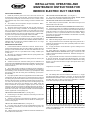
19. The following table shows the maximum current for 75 °C. Copper
wire with not more than 3 conductors in a raceway. It is based on the 1999
National Electrical CodeTable 310-16. The amperages shown are for 125%
and 100% wire sizing. If there are more than 3 conductors in a raceway,
derate these amperages per Table 310-15(b)(2)(a).
20. When connecting heaters with more than one stage, wire stage No. 1
so that it is the first stage on and the last stage off. Heaters with built-in PE
switches must follow this rule also. The stage number will be indicated on
the front of each PE switch.
INSTALLATION, OPERATING AND
MAINTENANCE INSTRUCTIONS FOR
INDEECO ELECTRIC DUCT HEATERS
SPMA
EZISERIWSPMAEZISERIWSPMAEZISERIW
%521%001MCM/GWA%521%001MCM/GWA%521%001MCM/GWA
2141080013 4810320/4
6121295112 402552052
42014010311822582003
0480210510 842013053
25566 0415710/2862533004
86584 0610020/3403083005
KW x 1000
Voltage
KW x 1000
Voltage x 1.73

21. The heater must be wired so
that it cannot operate unless air is
flowing over it. This can be accom-
plished by using a built-in airflow
switch, a built-in fan relay or any of
several other methods. See the
accompanying wiring diagram for
the method used with this heater
and provide appropriate interlock
wiring as illustrated.
22. National Electrical Code and
Underwriters Laboratories require
the heater manufacturer to supply
1) over-current protection where
heater total current exceeds 48
amperes and 2) any contactors
required for proper functioning of
temperature limiting controls.
Where these devices are not in-
cluded in the heater terminal box
of a UL listed heater, they are sup-
plied in a remote UL listed panel
board shown on the wiring dia-
gram.
23. If not supplied as part of this
heater, install a line disconnect
switch or main circuit breaker in
accordance with the National Elec-
trical Code. Depending upon the
heater’s location and accessibility,
a built-in disconnect switch may
meet this requirement.
24. All electrical connections in
the heater, including both field and
factory made connections, should
be checked for tightness before
operating the heater. In addition,
after a short period of operation, all
connections should again be
checked for tightness.
25. If heater is wired to a heating-
cooling thermostat, use a thermo-
stat with isolating circuits to prevent
possible interconnection of Class
2 outputs.
26a. If the area inside of the sheet
metal directly surrounding the heat-
ing element section is more than
1” smaller in length and/or width
than the duct in which the duct
heater is installed, the KW per
square foot of duct area should be
calculated as the heater nameplate
KW divided by the area inside the
sheet metal enclosure directly
around the heating elements.
26b. If the heating elements are
divided into several sections with
uncoiled resistance wire between
two or more coiled sections, maxi-
mum KW per sq. ft. should be cal-
culated as follows:
Heater nameplate KW
Number of heated sections x
area of one heated section
OPERATION & MAINTENANCE
NOTICE: ALL SOURCES OF SUPPLY MUST BE DISCONNECTED
BEFORE WORKING ON THIS EQUIPMENT
425 Hanley Industrial Court * St. Louis, Missouri 63144
(314) 644-4300 * FAX (314) 644-5332
To operate this heater make sure all associated control
equipment is on, energize main supply disconnect and
set controlling thermostat above ambient temperature.
This heater is equipped with automatic and manual reset
temperature limiting controls. If it fails to operate, make
sure manual resets are operative by pushing reset
buttons.
INSTALLATION DRAWINGS
Fig. 1 – Installation drawing of
flanged heater.
Fig. 2 – Installation drawing of slip-in
heater.
Fig. 3 – Installation drawing of two
stacked sections in a duct.
AIR FLOW REQUIREMENTS
Calculate KW per square foot of duct area as: heater namplate KW
duct area (Sq.Ft.)
Fig. 5 –Fig. 4 –
100
2
200 300 400 500 600 700 800 900 1000 1100 1200
4
6
8
10
12
14
16
0
0
100
2
200 300 400 500 600 700 800 900 1000 1100 1200
4
6
8
10
12
14
16
18
22
24
26
28
30
32
20
0
0
KW PER SQ. FT. DUCT AREA
MINIMUM AIR VELOCITY REQUIRED
(FEET PER MINUTE)
KW PER SQ. FT. DUCT AREA
MINIMUM AIR VELOCITY REQUIRED
(FEET PER MINUTE)
(see #26)
The only routine maintenance required is to check all
electrical connections, including field and factory made
connections, for tightness at least once each year or
operating season. In addition, of course, any filters in the
airstream must be kept clean so that adequate airflow is
maintained.
FINNED
TUBULAR
CONSTRUCTION
91 - 100° Inlet Air
81 - 90° Inlet Air
Below 80° Inlet A
ir
OPEN COIL
CONSTRUCTION
092d-1108
-
 1
1
-
 2
2


Unbranded B5SM Installation guide
- Category
- Space heaters
- Type
- Installation guide
- This manual is also suitable for
Ask a question and I''ll find the answer in the document
Finding information in a document is now easier with AI
Other documents
-
Procom PF09B Installation guide
-
Chromalox DH Operating instructions
-
 Indeeco OTL222 Installation guide
-
York Standard Air Handling Units User manual
-
Bryant 558J User manual
-
-
-
Carrier 50TCA04-A07 User manual
-
-
