Page is loading ...

E2
IP1935EN
rev. 2010-07-19
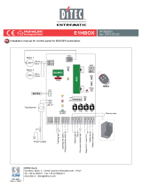
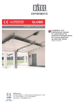
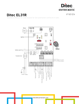
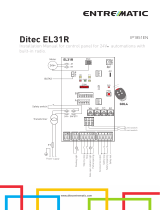
Installation manual for control panel for automations with two 230 V~ motors with built-in radio.
EN
DITEC S.p.A.
Via Mons. Banfi, 3 - 21042 Caronno Pertusella (VA) - ITALY
Tel. +39 02 963911 - Fax +39 02 9650314
www.ditec.it - [email protected]
TR
RF
R1 TC TM
Power supply
LN
UWV XZY
15 13 12 11 0 1 15689
A
B
ON
OFF
123 4
ON
OFF
123 4 5 6
AUX
PRG
ANT
SIG
POWER
SA
12
11
IN
230V~
-
+
Output 24 V= / max 0,5 A
Step-by-step
M2 closing limit switch
M1 closing limit switch
Electric lock
Lamp
Flashing light
Safety stop
Safety re-opening
Stop
GOL4
JR1
F1
COM
BIXMR2
230V~
Motor 1 Motor 2
com
com

2
IP1935EN 2010-07-19
All right reserved
All data and speci¿cations have been drawn up and checNed with the Jreatest care. The manufacturer cannot
however taNe an\ responsibilit\ for eventual errors, ommisions or incomplete data due to technical or illustrative
purposes.
INDEX
Subject Page
1. *eneral safet\ precautions 3
2. EC declaration of conformit\ 4
3. Technical data 4
3.1 Applications
4
4. Connection of power suppl\ 4
5. Commands 5
6. Outputs and accessories 6
7. Adjustments 7
8. Radio receiver operation 9
9. Start-up 9
10. TroubleshootinJ 10
11. Example application for Jates with one swinJinJ door winJ 11
12. Example application for Jates with two swinJinJ door winJs 13
13. Hold-to-run function mode 15

3
IP1935EN 2010-07-19
1. GENERAL SAFETY PRECAUTIONS
This installation manual is intended for professionall\ competent personnel onl\.
The installation, the power connections and the settinJs must be completed in conformit\ with *ood
:orNinJ Methods and with the reJulations in force.
Before installinJ the product, carefull\ read the instructions. Bad installation could be ha]ardous. The pacNaJinJ
materials (plastic, pol\st\rene, etc.) should not be discarded in the environment or left within reach of children,
as these are a potential source of ha]ard.
Before beJinninJ the installation checN that the product is in perfect condition.
'o not install the product in explosive areas and atmospheres the presence of Àammable Jas or fumes re-
presents a serious threat to safet\.
The safet\ devices (photocells, sensitive edJes, emerJenc\ stop, etc.) must be installed taNinJ into account
the provisions and the directives in force, *ood :orNinJ Methods, the installation area, the functional loJic of
the s\stem and the forces developed b\ the automation.
Before maNinJ power connections, checN that the ratinJ corresponds to that of the mains suppl\. A mul-
tipolar disconnection switch with a contact openinJ Jap of at least 3 mm must be included in the mains
suppl\. ChecN that upstream of the electrical installation an adeTuate residual current circuit breaNer and an
overcurrent cut out are ¿tted.
:hen reTuested, connect the automation to an effective earthinJ s\stem carried out as indicated b\ current
safet\ reJulations.
'urinJ installation, maintenance and repair operations, cut off the power suppl\ before openinJ the cover to
access the electrical parts.
To handle electronic parts, wear earthed antistatic conductive bracelets. The manufacturer of the moto-
risation declines all responsibilit\ in the event of components which are not compatible with the safe and
correct operation of the product.
For repairs or replacements of products onl\ oriJinal spare parts must be used.

4
IP1935EN 2010-07-19
2. EC DECLARATION OF CONFORMITY
Manufacturer: DITEC S.p.A.
Address: via Mons. Ban¿, 3 21042 Caronno P.lla (VA) - ITALY
declares that the control panel E2 (with receiver 433.92 MH]) is in conformit\ with the provisions of the follow-
inJ EC directives:
R&TTE Directive 1999/5/CE;
EMC Directive 2004/108/CE;
Low VoltaJe Directive 2006/95/CE.
Caronno Pertusella, 19-07-2010 Silvano AnJaroni
(ManaJinJ Director)
3. TECHNICAL DATA
3.1 Applications
4. CONNECTION OF POWER SUPPLY
Fix the control panel permanentl\. Pass the cables alonJ from the lower side of the container.
Before connectinJ the power suppl\, maNe sure the plate data correspond to that of the mains power suppl\.
An omnipolar disconnection switch with minimum contact Japs of 3 mm must be included in the mains suppl\.
ChecN that upstream of the electrical installation there is an adeTuate residual current circuit breaNer and a
suitable overcurrent cutout.
8se a 3x1.5 mm FROR 450/750V t\pe electric cable and connect to the terminals L (brown), N (blue),
(\ellow/Jreen) in the automation.
Secure the cable usinJ a special cable clamp.
MaNe sure there are no sharp edJes that ma\ damaJe the power suppl\ cable.
Connection to the mains power suppl\, in the section outside the automation, is made with independent channels
and separated from the connections to the control and safet\ devices.
SiSi
Si
S
Si
Si
S
Si
S
Si
Si
S
S
S
S
S
S
S
S
S
S
S
S
S
S
S
S
S
S
S
S
S
S
S
S
S
S
S
S
S
S
S
S
S
S
S
S
S
S
Si
S
S
S
S
S
S
S
S
S
S
S
S
S
S
S
S
lv
lv
v
lv
lv
v
lv
l
v
v
an
a
a
o
oo
o
o
o
An
An
A
An
An
n
n
n
An
A
n
n
A
n
n
An
n
n
n
n
An
n
A
n
n
n
n
n
n
An
A
A
n
n
n
n
A
n
n
n
n
n
A
n
n
n
n
n
n
An
A
A
n
An
n
n
n
n
A
n
n
n
An
A
n
n
n
n
A
n
n
n
n
n
n
n
n
n
n
n
n
n
A
n
n
n
n
n
n
n
n
J
Ja
Ja
Ja
Ja
Ja
Ja
J
Ja
Ja
J
ro
roro
o
ni
ni
n
ni
n
ni
ni
(M
(M
(M
(M
(M
(M
(M
M
(M
(M
(M
(M
M
M
M
M
(M
(M
M
M
M
(M
M
M
(M
M
(M
(M
(M
M
M
(M
(M
(M
(M
(M
M
M
M
(M
(M
(M
M
M
M
M
M
M
(
(
(
(M
M
M
M
(M
(
(
(
M
M
M
(M
M
(
(M
(
(M
(
(
(
M
(M
M
M
(
(M
(
(
(
(
M
M
M
M
M
M
(
(
(
M
M
M
M
M
M
(
(
M
M
M
M
M
M
M
M
(
M
M
M
M
M
M
(M
M
(M
M
M
M
M
M
M
M
M
M
M
(
(
(
(
(
(
(
(
an
an
an
an
a
n
an
an
an
n
n
an
n
an
an
a
an
an
an
an
a
a
an
a
an
n
n
n
an
a
a
an
an
a
n
an
an
an
a
a
an
n
n
an
a
an
a
an
an
a
an
n
an
a
a
a
a
a
n
n
n
a
a
a
a
a
n
n
a
a
a
a
a
n
n
n
n
n
n
n
a
a
a
a
n
n
n
n
n
a
a
a
a
a
n
n
n
an
n
n
a
an
a
a
n
n
n
n
n
a
a
a
n
n
a
a
a
a
n
n
n
aJ
aJ
aJ
aJ
aJ
aJ
aJ
aJ
aJ
aJ
aJ
aJ
aJ
aJ
aJ
aJ
a
a
a
aJ
aJ
aJ
a
a
aJ
a
a
a
a
a
a
aJ
a
a
J
aJ
a
a
a
a
a
a
a
a
a
aJ
aJ
a
a
a
J
J
J
aJ
a
aJ
a
aJ
a
a
aJ
aJ
J
J
a
a
a
a
a
a
a
a
J
J
J
a
a
a
a
a
aJ
aJ
aJ
aJ
J
a
a
a
a
aJ
J
J
J
J
J
J
a
a
a
J
J
J
J
J
J
a
a
aJ
J
J
J
J
J
J
a
a
J
J
J
J
J
J
J
J
J
J
J
J
J
J
J
J
J
J
J
J
J
J
J
J
J
J
J
J
J
in
in
in
in
in
i
n
i
n
n
i
i
i
i
n
i
i
i
i
i
i
i
J J
J
J
J
J
J
J
J
J
J
J
J
J
J
J
J
J
J
J
J
J
J
J
J
J
J
J
J
J
J
J
J
J
J
J
J
J
J
J
J
J
J
J
J
J
J
J
J
J
J
J
J
J
J
J
J
J
J
J
J
J
J
J
J
J
J
J
J
J
J
J
J
J
J
J
J
J
J
J
J
J
J
D
D
D
D
Di
Di
Di
Di
Di
Di
D
D
D
D
D
i
Di
D
D
Di
D
Di
D
D
Di
Di
Di
Di
D
D
D
D
D
D
D
D
i
i
D
D
Di
Di
D
D
D
D
i
i
Di
D
D
D
Di
i
i
D
D
D
D
Di
D
Di
D
D
i
i
D
D
D
D
Di
Di
D
D
i
D
D
D
D
D
D
i
i
Di
D
D
D
D
D
D
i
D
D
D
D
D
D
D
i
i
i
Di
D
D
D
D
i
i
i
D
D
D
D
D
i
D
D
D
D
D
i
i
i
D
D
D
D
i
D
D
D
D
D
re
re
re
re
re
re
re
re
e
re
e
re
re
re
re
re
e
re
e
re
r
r
r
r
re
re
re
e
e
e
e
r
r
r
r
r
re
re
e
e
e
e
re
e
e
r
r
re
re
e
e
e
e
e
e
e
r
r
r
re
e
e
e
e
e
re
re
r
e
e
e
e
e
e
e
e
e
re
r
e
re
e
e
e
e
re
e
r
r
re
r
e
e
e
e
re
r
r
r
r
re
e
e
re
r
r
r
r
r
r
r
e
e
r
r
r
r
r
re
e
r
r
r
r
re
e
e
e
ct
ct
ct
ct
ct
ct
ct
ct
t
t
ct
ct
ct
ct
ct
c
ct
ct
t
t
t
t
ct
ct
ct
t
ct
t
t
t
ct
ct
c
ct
c
c
ct
ct
ct
t
ct
c
ct
c
c
c
ct
t
t
ct
c
c
c
c
c
c
ct
t
t
t
c
c
c
c
c
c
c
c
c
ct
t
t
t
ct
c
c
c
c
c
c
ct
t
t
t
t
c
c
c
c
c
ct
c
c
c
ct
c
t
t
t
t
c
c
c
c
c
c
c
t
t
t
ct
c
c
t
t
c
o
or
or
or
o
o
or
or
or
o
o
or
r
or
or
o
o
or
o
o
o
o
o
o
o
r
r
r
or
or
o
o
o
or
o
o
or
or
r
or
o
o
or
o
o
o
o
o
o
or
r
r
r
o
o
o
o
o
o
o
or
r
r
r
or
or
o
o
o
or
o
or
o
o
o
o
r
r
r
or
o
o
o
o
o
o
o
or
r
r
r
r
o
o
o
o
or
o
r
r
o
o
r
o
or
or
)
)
)
)
)
)
)
)
)
)
)
)
)
)
)
)
)
)
)
)
)
)
)
)
)
)
)
)
)
)
)
)
)
)
)
)
)
)
)
)
)
)
)
)
)
)
)
E2 E2J
Power supply 230 V~ / 50 H] 120 V~ / 60 H]
F1 fuse F5A F6,3A
1 motor output 230 V~ / 5 A 120 V~ / 6,3 A
2 motors output 230 V~ / 2 x 2,5 A 120 V~ / 2 x 3,15 A
Accessories power supply 24 V= / 0,5 A
Temperature -20 °C / +55 °C
Degree of protection IP55
Memorizable radio codes 200
Radio frequency 433,92 MH]
i
NOTE: the given operating and performance features can only be guaranteed with the use of DITEC
accessories and safety devices.

5
IP1935EN 2010-07-19
5. COMMANDS
Command Function Description
1
5 N.O. STEP-BY-STEP
WITH AUTOMATIC
CLOSING
With DIP1A=OFF and TCMA;, the closinJ of the contact acti-
vates openinJ or closinJ operations in the followinJ seTuence:
open-stop-close-open.
NOTE: the stop is not permanent but lasts for a duration set
by TC.
STEP-BY-STEP
WITHOUT AUTOMATIC
CLOSING
With DIP1A=OFF and TC=MA;, the closinJ of the contact acti-
vates openinJ or closinJ operations in the followinJ seTuence:
open-stop-close-open.
OPENING WITH
AUTOMATIC
CLOSING
With DIP1A=ON and TCMA;, the closinJ of the contact acti-
vates the openinJ operation.
OPENING WITHOUT
AUTOMATIC
CLOSING
With DIP1A=ON and TC=MA;, the closinJ of the contact acti-
vates the openinJ operation.
NOTE: once the automation stops, the closing of the contact
performs the opposite operation to the one performed before
stop.
1
6 N.C. SAFETY STOP With DIP5B=ON, all operations are stopped and/or blocNed
when the safet\ contact is opened.
1
6 N.O. CLOSING With DIP5B=OFF, the closinJ of the contact activates the clo-
sinJ operation.
1
8 N.C. REVERSE
SAFETY CONTACT
The openinJ of the safet\ contact triJJers a reversal of motion
(re-openinJ) durinJ closinJ.
1
9 N.C. STOP The openinJ of the safet\ contact stops the current operation.
1
9 N.O. HOLD-TO-RUN
FUNCTION
With DIP1A=ON and DIP5B=OFF, the openinJ of the 1-9 con-
tact enables the hold-to-run function.
- hold-to-run openinJ 1-3;
- hold-to-run closinJ 1-4.
NOTE: any safety device, automatic closing and plug-in card
inserted in AUX is disabled.
0 11 N.C. M2 CLOSING
LIMIT SWITCH
With TM=MA;, the openinJ of the contact stops the closinJ
operation of motor 2 (M2).
With TM=MA; and DIP3B=OFF, the openinJ of the contact
stops the closinJ operation of motor 1 (M1).
0 11 N.O. M2 PROXIMITY
LIMIT SWITCH
See paJe 12-14.
0
12 N.C. M1 CLOSING
LIMIT SWITCH
With TM=MAX, the openinJ of the contact stops the closinJ
operation of motor 1 (M1).
With TM=MAX and DIP3B=OFF, the openinJ of the contact
stops the openinJ operation of motor 1 (M1).
0 12 N.O. M1 PROXIMITY
LIMIT SWITCH
See paJe 12-14.
PRG
N.O. TRANSMITTERS
STORAGE AND
CANCELLATION
WARNING: the BIXMR2 storage module must be inserted.
Transmitter storage:
- press the PRG Ne\ (the SIG LED comes on),
- transmit the transmitter to be stored (the SIG LED Àashes),
- wait 10 s to complete storaJe (the SIG LED Joes out).
Transmitter cancellation:
- press the PRG Ne\ for 3 sec (the SIG LED Àashes),
- press the PRG Ne\ for another 3 sec (the SIG LED Àashes
TuicNl\).
WARNING: make a jumper for all the N.C. contacts if not in use. The terminals with the same number
are equal.

6
IP1935EN 2010-07-19
6. OUTPUTS AND ACCESSORIES
Output Value - Accessories Description
01
+
-
24 V= / 0,5 A
Accessories power supply. Power suppl\ output for external ac-
cessories, includinJ automation status lamp.
1 11
24 V= / 3 W
Open automation lamp. Onl\ with the 0-11 limit switch (N.C.) con-
nected and DIP3B=OFF the liJht switches off when the automation
is closed.
1
12
24 V= / 3 W
Closed automation lamp. Onl\ with the 0-12 limit switch (N.C.)
connected and DIP3B=OFF the liJht switches off when the automa-
tion is open.
1
13
24 V= / 3 W
Open automation lamp. The liJht switches off when the automation
is closed.
0
15 12 V= / 15 W
Electric lock. Activated upon ever\ openinJ command.
W
N
LAMP
230 V~ / 100 W
Flashing light. Activated durinJ openinJ and closinJ operations.
X
L
230 V~ / 100 W
Courtesy light. In 1 motor mode onl\ (with DIP3B=OFF and no motor
connected to terminals X-=-Y), an external courtes\ liJht that turns
on for 180 s with ever\ openinJ (total or partial), step-b\-step and
closinJ command can be connected.
AUX
The control panel has one housinJ for pluJ-in cards such as a radio
receiver t\pe, maJnetic loops, etc.
PluJ-in card operatinJ is selected usinJ DIP1A.
WARNING: the plug-in cards must be inserted and removed with the
power supply disconnected.
COM
BIXMR2
The storaJe module allows remote controls to be stored.
If the control panel is replaced, the BIXMR2 storaJe module beinJ
used can be inserted in the new control panel.
WARNING: the storage module must be inserted and removed with
the power supply disconnected.

7
IP1935EN 2010-07-19
7. ADJUSTMENTS
Description OFF ON
DIP1A Command 1-5 operation.
NOTE: it also sets operating mode of the
plugin cards connected on AUX.
Step-b\-step. OpeninJ.
DIP2A Restore automatic closing time. 50% 100%
DIP3A Automation status at power on.
Indicates how the control panel considers
automation when powered up.
Open.
NOTE: with limit switches
installed, preferably set
DIP3A=OFF.
Closed.
NOTE: if the automatic clo-
sing function is not used,
preferably set DIP3A=ON.
DIP4A Electric lock release. Disabled. Enabled.
DIP1B Maximum power start. Disabled.
The motor starts with the
voltaJe set with trimmer RF.
Enabled.
The motor starts at maxi-
mum power for 1 s.
DIP2B FUTURE USE //
DIP3B Automation type. 1 motor automation. 2 motors automation.
DIP4B Automation model. FACIL Other automations.
DIP5B Command 1-6 operation. ClosinJ. Stop.
DIP6B Reversal safety switch function. With the automation blo-
cNed, if the contact 1-8 is
open, it is possible to activa-
te the openinJ operation.
With the automation blo-
cNed, if the contact 1-8 is
open, an\ operation is im-
possible.
Description OFF ON
JR1 Incorporated radio receiver. Disabled. Enabled.

8
IP1935EN 2010-07-19
Trimmer Description
RF
min max
Power adjustment. Adjusts the voltaJe supplied to the motor.
TR
0 s
3 s
30 s
20 s
10 s
Setting motor 1 (M1) closing delay time. From 0 to 30 s.
When closinJ, motor 1 (M1) arrives after a dela\ set with trimmer TR relative to motor
2 (M2).
When openinJ, motor 2 (M2) starts after a dela\ of 3 s relative to motor 1 (M1).
With TR=MIN the door winJs start simultaneousl\.
NOTE: setting TR=MIN with non-overlapping door wings and setting TR>3 s with
overlapping door wings is recommended.
R1
min Disabled
Obstacle thrust adjustment.
The control panel is eTuipped with a safet\ s\stem that stops motion if an obstacle is
encountered durinJ an openinJ operation and stops or inverts the movement durinJ
a closinJ operation.
R1=MIN Jives maximum obstacle sensitivit\ (minimum thrust).
R1=MAX disables obstacle detection (maximum thrust).
TC
0 s Disabled
120 s
Setting automatic closing time. From 0 to 120 s.
With DIP2A=OFF, once a safet\ switch has been activated, the counter starts as soon
as the safet\ switch is released (for example after passinJ throuJh the photocells),
and lasts for a period of time set with trimmer TC (50%).
With DIP2A=ON, the counter starts when automation is opened and lasts for the entire
duration set with trimmer TC (100%).
NOTE: after the activation of the stop command, once contact 1-9 has closed again,
automatic closing is only enabled after a total, partial or step-by-step opening com-
mand.
TM
10 s 120 s
60 s
Operation time adjustment. From 10 to 120 s.
NOTE: set TM=MAX with limit switches installed.
LED On Flashing
SIG
Transmitter enablinJ/storaJe phase. Reception of a radio transmission.
Cancellation of transmitters in proJress.
BIXMR2 memor\ damaJed.
IN
Receipt of command or chanJe in status of
a dip-switch.
/
11
0-11 limit switch contact is open.
/
12
0-12 limit switch contact is open.
/
SA At least one of the safet\ contacts is open. Operations count performed (onl\ when con-
trol panel is switched on):
each rapid Àash = 1000 operations
each slow Àash = 10000 operations
POWER Power suppl\ on.
/

9
IP1935EN 2010-07-19
8. RADIO RECEIVER OPERATION
The control panel is eTuipped with a radio receiver with a freTuenc\ of 433.92 MH]. The antenna consists of
a 173 mm lonJ riJid wire.
It is possible to increase the ranJe of the radio b\ connectinJ the external antenna of the ÀashinJ liJhts, or b\
installinJ the tuned antenna (BIXAL).
NOTE: to connect the external antenna to the control panel, use a coaxial cable type RG58 (max 10 m).
Up to 200 remote controls can be stored in the BIXMR2 storaJe module.
WARNING: if the radio receiver on the control panel is not used, set JR1=OFF and remove the storage mo-
dule.
Refer to the transmitters user manual to store, clone and delete transmitters.
From one to four CH Ne\s of a sinJle transmitter can be stored in the control panel.
If onl\ one (an\) CH Ne\ of the transmitter is stored, command 1-5 (step-b\-step/openinJ) is carried out.
If from two to four CH Ne\s of a sinJle transmitter are stored, the functions matched with the CH Ne\s are as
follows:
- CH1 = command 1-5 step-b\-step/openinJ;
- CH2 = partial openinJ command, it causes the automation to open for about 8 s;
- CH3 = command to switch on/off the courtes\ liJht;
- CH4 = stop command, eTuivalent to impulsive command 1-9.
If the control panel is replaced, the BIXMR2 storaJe module beinJ used can be inserted in the new control
panel.
WARNING: the BIXMR2 storage module must be inserted and removed with the power supply disconnected.
9. START-UP
WARNING The operations in point 5 are performed without safety devices.
The trimmer can only be adjusted with the automation idle.
1- MaNe a jumper for the N.C. safet\ contacts.
2- ChecN the application t\pe selected.
3- If installed, adjust the openinJ and closinJ stop limit switches.
NOTE: limit switches must be kept pressed until the operation has been completed.
4- Set TR!3 s in case of automation with two overlappinJ door winJs.
5- Switch on and checN that the automation is operatinJ correctl\ with subseTuent openinJ and closinJ
commands.
If installed, checN that the limit switches are activated.
NOTE: if the direction of rotation of the motor is incorrect for the desired direction of the automation, swap
the U-V or X-Y phases.
6- Connect the safet\ devices (removinJ the relative jumpers) and checN the\ worN correctl\.
7- If reTuired, adjust the automatic closinJ time with the TC trimmer.
WARNING: the automatic closing time after a safety device has triggered depends on the DIP2A setting.
8- Set RF trimmer to a position that allows the automation to function correctl\ while ensurinJ the safet\ of
the user in the event of collision.
9- Set the obstacle thrust with the R1 trimmer.
NOTE: if the door wing closing second encounters an obstacle, both door wings are reopen and the sub-
sequent closing operation is performed one door wing at a time.
WARNING: check that the working forces exerted by the door wings are compliant with EN12453-EN12445
regulations.
10- Connect an\ other accessories and checN the\ operate correctl\.
11- Once the start-up and checN procedures are completed, close the container.
WA
R
NI
N
G
The operations in point 5 are per
f
ormed without sa
f
et
y
devices.
The trimmer can onl
y
be adjusted with the automation idle.
i
NOTE: in the event of servicing or if the control panel is to be replaced, repeat the start-up procedure.

10
IP1935EN 2010-07-19
10. TROUBLESHOOTING
Problem Possible causes Remedy
The automation does not
open or close.
No power.
(POWER led off).
ChecN that the control panel is powe-
red correctl\.
Short circuited accessories.
(POWER led off).
Disconnect all accessories from termi-
nals 0-1 (voltaJe must be 24 V=) and
reconnect one at a time.
Blown line fuse.
(POWER led off).
Replace F1 fuse.
Safet\ contacts are open.
(SA led on).
ChecN that the safet\ contacts are clo-
sed correctl\ (N.C.).
The remote control does not worN. ChecN the correct memori]ation of the
transmitters on the incorporated radio.
If there is a fault with the radio receiver
that is incorporated in the control panel,
the radio control code can be read b\
removinJ the storaJe module.
The automation opens but
does not close.
Safet\ contacts are open.
(SA led on).
ChecN that the safet\ contacts are clo-
sed correctl\ (N.C.).
Photocells are activated.
(SA led on).
ChecN that the photocells are clean and
operatinJ correctl\.
The automatic closinJ does not worN. ChecN that the TC trimmer is not set at
the maximum.
The automation is ver\
weaN and does not invert
the movement.
The motor’s condenser has an incor-
rect capacit\ value.
Replace the motor’s condenser.
External safet\ devices not
activatinJ.
Incorrect connections between the
photocells and the control panel.
Connect N.C. safet
\ devices toJether in
series and remove an\ bridJes on the
control panel terminal board.
The remote control has li-
mited ranJe and does not
worN with the automation
movinJ.
The radio transmission is impeded b\
metal structures and reinforced con-
crete walls.
Install the antenna outside. Substitute
the transmitter batteries.

11
IP1935EN 2010-07-19
11. EXAMPLE APPLICATION FOR GATES WITH ONE SWINGING DOOR WING
FiJ. 11.1
FiJ. 11.3
FiJ. 11.2
When the control panel is used in applications with
one swinJinJ door winJ, one of the followinJ operatinJ
modes ma\ be selected:
(Fig. 11.1) Door wing stops against mechanical
stops and in the event of obstacle detection.
Set an operatinJ time of 2-3 s lonJer than the ef-
fective time taNen b\ the door winJ (TMMAX) and
bridJe terminals 0-11-12 with jumpers.
In this con¿Juration, the door winJ will stop aJainst
mechanical openinJ and closinJ stops and in the
event of obstacle detection.
(Fig. 11.2) Door wing stops against limit switches
and in the event of obstacle detection.
The N.C. contacts of the openinJ and closinJ limit
switches are connected in series with the motor
phases. Set an operation time TMMAX and bridJe
terminals 0-11-12 with jumpers.
In this con¿Juration, the door winJ stops aJainst the
openinJ and closinJ limit switches and in the event
of obstacle detection.
(Fig. 11.3) Door wing stops against limit switches
and inverts in the event of obstacle detection.
Set an operatinJ time TM=MAX and connect the
openinJ and closinJ limit switches N.C. contacts to
terminals 0-11-12.
In this con¿Juration, the door winJ stops when the
limit switches are activated. In the event of obstacle
detection while openinJ, the door winJ stops, perfor-
minJ a disenJaJement operation, whereas durinJ
a closin
J operation, the door winJ reopens.
R1 TM
15 13 12 11 0 1 15689
A
B
ON
OFF
123 4
ON
OFF
123 4 5 6
R1<MAX
TM<MAX
DIP3B=OFF
R1 TM
15 13 12 11 0 1 15689
A
B
ON
OFF
123 4
ON
OFF
123 4 5 6
R1<MAX
TM=MAX
DIP3B=OFF
Opening limit switch
Closing limit switch
R1 TM
15 13 12 11 0 1 15689
A
B
ON
OFF
123 4
ON
OFF
123 4 5 6
R1<MAX
TM<MAX
DIP3B=OFF
UWV
230V~
com
Motor 1
Limit switch
(230V - 5A)

12
IP1935EN 2010-07-19
(Fig. 11.4) Door wing stops against mechanical stops
and inverts in the event of obstacle detection.
Set an operatinJ time of 2-3 s lonJer than the ef-
fective time taNen b\ the door winJ (TMMAX) and
position the proximit\ limit switches 2-3 s ahead of
the mechanical stop.
In this con¿Juration, the door winJ stops aJainst its
respective mechanical closinJ and openinJ stop.
In the event of obstacle detection before the acti-
vation of the proximit\ limit switch while openinJ,
the door winJ stops, performinJ a disenJaJement
operation; after the proximit\ limit switch is activated,
the door winJ stops aJainst the obstacle.
In the event of obstacle detection while closinJ and
before the activation of the proximit\ limit switch,
the door winJ reopens; after the proximit\ limit
switch is activated, the door winJ stops aJainst the
obstacle.
(Fig. 11.5) Door wing stops against the limit switch
when opening and against the mechanical stop
when closing, and inverts in the event of obstacle
detection.
Set an operatinJ time 2-3 s lonJer than the effective
time taNen b\ the door winJ (TMMAX), and the
closinJ proximit\ switch 2-3 s earlier than the mecha-
nical stop and connect the N.C. openinJ limit switch
in series to the openinJ phase of the motor.
In this con¿Juration the winJ
stops on the closinJ
mechanical stop while on the openinJ, it stops and
releases when the relative limit switch operates.
DurinJ openinJ operation, in the event of obstacle
detection, the winJ stops, performinJ a disenJaJe-
ment operation.
DurinJ closinJ operation, in the event of obstacle
detection before the proximit\ switch operates, the
winJ reopens; after the proximit\ switch operates,
the winJ stops on the closinJ mechanical stop.
FiJ. 11.4
R1 TM
15 13 12 11 0 1 15689
A
B
ON
OFF
123 4
ON
OFF
123 4 5 6
R1<MAX
TM<MAX
DIP3B=OFF
Opening proximity switch
Closing proximity switch
FiJ. 11.5
R1 TM
15 13 12 11 0 1 15689
A
B
ON
OFF
123 4
ON
OFF
123 4 5 6
R1<MAX
TM<MAX
DIP3B=OFF
UWV
230V~
com
Motor 1
Opening
limit switch
(230V - 5A)
Closing proximity switch

13
IP1935EN 2010-07-19
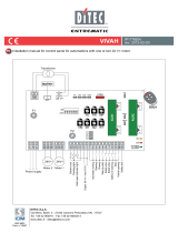
12. EXAMPLE APPLICATION FOR GATES WITH TWO SWINGING DOOR WINGS
FiJ. 12.1
FiJ. 12.3
FiJ. 12.2
When the control panel is used in applications with two
overlappinJ swinJinJ door winJs, one of the followinJ
operatinJ modes ma\ be selected:
(Fig. 12.1) Door wings stop against mechanical
stops and in the event of obstacle detection.
Set an operatinJ time of 2-3 s lonJer than the ef-
fective time taNen b\ the door winJs (TMMAX) and
bridJe terminals 0-11-12 with jumpers.
In this con¿Juration, each door winJ will stop aJainst
mechanical openinJ and closinJ stops and in the
event of obstacle detection.
(Fig. 12.2) Door wings stop against limit switches
and in the event of obstacle detection.
The N.C. contacts of the openinJ and closinJ limit
switches are connected in series with the motor
phases. Set an operatinJ time TMMAX and bridJe
terminals 0-11-12 with jumpers.
In this con¿Juration, each door winJ will stop aJainst
the openinJ and closinJ limit switches and in the
event of obstacle detection.
(Fig. 12.3) Door wings stop against limit switches
and invert in the event of obstacle detection.
Set an operatinJ time TM=MAX and connect the clo-
sinJ limit switch N.C. contacts to terminals 0-11-12
and the openinJ limit switch N.C. contacts in series
with the open phase of each motor.
In this con¿Juration, each door winJ stops when the
limit switches are activated.
In the event of obstacle detection while openinJ, onl\
the door winJ that detects the obstacle stops, perfor-
min
J a disenJaJement operation, whereas durinJ a
closinJ operation, both door winJs reopen.
TR R1 TM
15 13 12 11 0 1 15689
TR>3 s
R1<MAX
TM<MAX
15 13 12 11 0 1 15689
UWV
230V~
com
Motor 1
230V~
com
Motor 2
Limit switch
(230V - 5A)
TR R1 TM
TR>3 s
R1<MAX
TM<MAX
XZY
15 13 12 11 0 1 15689
UWV
230V~
com
Motor 1
230V~
com
Motor 2
Opening limit switch
(230V - 5A)
Closing limit switch
Closing limit switch
TR R1
TR>3 s
R1<MAX
TM=MAX
XZY
TM

14
IP1935EN 2010-07-19
(Fig. 12.4) Door wings stop against mechanical stops
and invert in the event of obstacle detection.
Set an operatinJ time 2-3 s Jreater than the effective
time taNen b\ the door winJs (TMMAX) and connect
the closinJ proximit\ switch N.O. contacts to termi-
nals 0-11-12, positioninJ the proximit\ switches 2-3
s ahead of the mechanical stop.
In this con¿Juration, each door winJ stops aJainst its
respective mechanical closinJ and openinJ stop.
In the event of obstacle detection while openinJ,
onl\ the door winJ that detects the obstacle stops,
performinJ a disenJaJement operation.
In the event of obstacle detection durinJ closinJ and
before the activation of the proximit\ switch, the door
winJs reopen; after the activation of the proximit\
switch, the door winJs stop aJainst the obstacle.
(Fig. 12.5) Door wings stop against the limit
switches when opening and against the mechani-
cal stops when closing, and invert in the event of
obstacle detection.
Set an operatinJ time 2-3 s lonJer than the effective
time taNen b\ the door winJs (TMMAX), connect
the closinJ proximit\ switches to terminals 0-11-12
and set them 2-3 s earlier than the mechanical stops.
Connect the N.C. openinJ limit switch in series to
the openinJ phase of each motor.
In this con¿Juration, each win
J stops on its closinJ
mechanical stop and durinJ openinJ when the rela-
tive limit switches operate.
DurinJ openinJ operation, in the event of obstacle
detection, the winJ stops and releases.
DurinJ closinJ operation, in the event of obstacle
detection before both the closinJ limit switches have
been triJJered, both winJs reopen.
After each limit switch has been triJJered the cor-
respondinJ winJ stops on the closinJ mechanical
stop.
FiJ. 12.4
FiJ. 12.5
TR R1 TM
15 13 12 11 0 1 15689
TR>3 s
R1<MAX
TM<MAX
Closing proximity switch
Closing proximity switch
Closing proximity switch
Closing proximity switch
15 13 12 11 0 1 15689
UWV
230V~
com
Motor 1
230V~
com
Motor 2
Opening limit switch
(230V - 5A)
TR R1
TR>3 s
R1<MAX
TM<MAX
XZY
TM

15
IP1935EN 2010-07-19
FiJ. 13.1
13. HOLD-TO-RUN FUNCTION MODE
Opening limit switch
Closing limit switch
R1 TM
15 13 12 11 0 1 15689
A
B
ON
OFF
123 4
ON
OFF
123 4 5 6
R1<MAX
TM=MAX
DIP5B=OFF
DIP1A=ON
i
NOTE: to use the control panel in hold-to-run
mode, disconnect terminal 9.
In this case, the openinJ command (1-5) and the closinJ
command (1-6) operate onl\ if Nept pressed, if released
the automation will stop. Automatic closinJ and radio
remote controls are disabled.
N
O
TE: to use the control panel in hold-to-run
m
ode
,
disconnect terminal
9
.

TM
DITEC S.p.A. Via Mons. Ban¿, 3 21042 Caronno P.lla (VA) Ital\ Tel. +39 02 963911 Fax +39 02 9650314
www.ditec.it [email protected]
DITEC BELGIUM LO.EREN Tel. +32 9 3560051 Fax +32 9 3560052 www.ditecbelJium.be DITEC DEUTSCHLAND OBERURSEL
Tel. +49 6171 914150 Fax +49 6171 9141555 www.ditec-Jerman\.de DITEC ESPAÑA ARENYS DE MAR Tel. +34 937958399
Fax +34 937959026 www.ditecespana.com DITEC FRANCE MASSY Tel. +33 1 64532860 Fax +33 1 64532861 www.ditecfrance.com
DITEC GOLD PORTA ERMESINDE-PORTUGAL Tel. +351 22 9773520 Fax +351 22 9773528/38 www.Joldporta.com DITEC SVIZZERA
BALERNA Tel. +41 848 558855 Fax +41 91 6466127 www.ditecswiss.ch DITEC ENTREMATIC NORDIC LANDSKRONA-SWEDEN
Tel. +46 418 514 50 Fax +46 418 511 63 www.ditecentrematicnordic.com DITEC TURCHIA ISTANBUL Tel. +90 21 28757850
Fax +90 21 28757798 www.ditec.com.tr DITEC AMERICA ORLANDO-FLORIDA-USA Tel. +1 407 8880699 Fax +1 407 8882237
www.ditecamerica.com DITEC CHINA SHANGHAI Tel. +86 21 62363861/2 Fax +86 21 62363863 www.ditec.cn
/