
EN
Control CS 320-T / Rev.A 1.01 – 1
Operating Instructions
Control CS 320-T

2 – Control CS 320-T / Rev.A 1.01 Control CS 320-T / Rev.A 1.01 – 3
1. Contents
1. Contents. . . . . . . . . . . . . . . . . . . . . . . . . . . . . 2
2. Information in this document . . . . . . . . . . . . 3
3. General safety instructions . . . . . . . . . . . . . . 3
4. Product overview. . . . . . . . . . . . . . . . . . . . . . 4
4.1 Product description...................4
4.2 Variants ...........................4
4.3 MotherboardCS320 .................5
5. Installation. . . . . . . . . . . . . . . . . . . . . . . . . . . 6
5.1 Safety instructions for installation ........6
5.2 Mains connection ....................6
5.3 Internal fuse protection................7
5.4 Mains voltage selection ...............8
5.5 Supply to external devices
(only with 400 V / 3-phase connection) ....8
5.6 Connection of electronic limit position system
absolute value encoder (AWG) ..........9
5.7 Mechanical limit switch (MEC) connection..9
5.8 Connection of command devices........12
5.9 Terminal assignment, relay outputs ......14
5.10 Connection of programmable inputs . . . . . 14
5.11 Safety input per EN 12453 ............17
5.12 Connection of frequency converter ......18
5.13 Connection of LCD monitor............19
5.14 Connection of MS BUS components .....19
6. Initialisation. . . . . . . . . . . . . . . . . . . . . . . . . 20
7. Setting the limit positions . . . . . . . . . . . . . . 21
7.1 Checking the drive / travel direction .....21
7.2 Setting the mechanical limit switches ....21
7.3 Setting the electronic end position system
using the setting buttons on the
circuit board .......................21
7.4 Setting the electronic limit position system via
the LCD monitor ....................22
7.5 Setting the intermediate positions of the
electronic limit position system via the LCD
monitor ..........................22
8. Programming . . . . . . . . . . . . . . . . . . . . . . . . 23
8.1 Overview of the LCD monitor ..........23
8.2 LCD monitor operating modes..........23
8.3 Expert menu.......................24
8.4 RESET............................24
8.5 RESETTING the controller with
LCDmonitor.......................25
8.6 RESETTING the controller without
LCDmonitor.......................25
9. Navigator (only LCD monitor) . . . . . . . . . . . 26
10. Functional overviews . . . . . . . . . . . . . . . . . . .28
10.1 Automatic mode....................28
10.2 Input operating mode ................29
10.3 Explanations of the relay modes:........34
10.4 Explanations of the inputs: ............37
10.5 Diagnosis operating mode / error memory. 39
11. Fault display and remedial measures. . . . . . .41
11.1 Fault display on the LCD monitor........41
11.2 Fault display via LED .................42
12. Technical data . . . . . . . . . . . . . . . . . . . . . . . .44
12.1 Mechanical and electrical data .........44
12.2 Category and performance level of the
safety function per EN ISO 13849-1 .....45
13. Service . . . . . . . . . . . . . . . . . . . . . . . . . . . . . .46
14. Manufacturer’s declaration . . . . . . . . . . . . . .47
15. Annex . . . . . . . . . . . . . . . . . . . . . . . . . . . . . . .48
15.1 Safety circuit measuring points .........48
15.2 Overview of the connections ...........50

Control CS 320-T / Rev.A 1.01 – 3
EN
2 – Control CS 320-T / Rev.A 1.01 Control CS 320-T / Rev.A 1.01 – 3
3. General safety instructions
WARNING!
Failure to comply with the documentation could
result in life-threatening danger!
Be sure to follow all the safety instructions in this
Be sure to follow all the safety instructions in this
document.
document.
Warranty
The function and safety of the equipment is only guaranteed
if the warning and safety instructions included in these
operating instructions are adhered to.
The manufacturer is not liable for personal injury or damage
to property if these occur as a result of the warnings and
safety advice being disregarded.
The manufacturer does not accept any liability or warranty
for damage due to the use of non-approved spare parts and
accessories.
Intended use
ThecontrollerCS320-Tisdesignedexclusivelyforcontrolling
door systems through drives with mechanical limit switches
(MEC) or an electronic limit position system (AWG).
Target group
Onlyqualiedandtrainedelectriciansmayconnect,
programme and service the control.
Qualiedandtrainedelectriciansmustmeetthefollowing
requirements:
− Knowledgeofthegeneralandspecicsafetyandaccident
prevention regulations,
− Knowledge of the relevant electrical regulations,
− Training in the use and care of appropriate safety
equipment,
− Capable of recognising the dangers associated with
electricity.
Original operating instructions
− Copyright.
− No part of these instructions may be reproduced without
our prior approval.
− Subject to alterations in the interest of technical progress.
− All dimensions given in mm.
− The diagrams in this manual are not to scale.
Key to symbols
WARNING!
Indicates a hazard with a medium level of risk which, if not
avoided, could result in death or serious injury.
CAUTION!
Indicates a hazard with a low level of risk which, if not
avoided, could result in minor or moderate injury.
ATTENTION!
Indicates an imminent danger of damage or destruction.
CHECK
Indicates a check to be performed.
REFERENCE
Reference to separate documents which must be complied
with.
Action requestAction request
− List, itemisation
➔ Reference to other sections of this document
2. Information in this document

4 – Control CS 320-T / Rev.A 1.01 Control CS 320-T / Rev.A 1.01 – 5
4 – Control CS 320-T / Rev.A 1.01
Instructions regarding installation and connection
− The control is designed with X type terminals.
− The system must be disconnected from the electricity supply
before carrying out any electrical work. It must be ensured
that the electricity supply remains disconnected for the
duration of the work.
− Local protective regulations must be complied with.
− Consultthemanufacturerbeforecarryingoutmodications
or replacing the mains connection cable.
− In general, an original wiring harness from
MFZGmbH&Co.KGshouldbeusedforestablishingthe
connection between the door drive and controller. Changes
or replacements shall only take place following consultation
with the manufacturer and approval by the same.
Information concerning operation
− Unauthorised persons (particularly children) should not be
allowed to play with permanently installed adjusting or
control devices.
Observe the valid standards and regulations!
4. Product overview
4.1 4.1 Product descriptionProduct description
ThecontrollerCS320-Tisdesignedforuseinindustrial
areas and can be used with all door types in these areas. It
is possible to connect drives with mechanical limit switches
(MEC) or an electronic limit position system (AWG).
All the necessary command devices and safety elements can
be connected, set and evaluated.
The CS 320-T is based on the automatic control CS 320.
DuringtheCLOSEmovement,dead-manoperationisxed.
During the OPEN movement, it is possible to select pulse
operation or dead-man operation.
The connections for the safety equipment have no function
and cannot be activated. All the necessary command devices
can be connected, set and evaluated.
Programming takes place via a pluggable LCD monitor.
Alternatively, a service tool is available as an accessory.
The service tool consists of a stick and an app.
ThefollowingsuppliervariantsofthecontrollerCS320-Tare
possible:
4.2 4.2 VariantsVariants
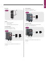
Housing variants:
− ControllerCS320-Tinthe“standard”housing
− ControllerCS320-Tinthe“combination”housingwith
integrated mounting rail for additional components
Variants of the pluggable LCD monitor:
− LCD monitor on the circuit board
− LCD monitor in the housing cover
− Hard-wiredLCDmonitor,pluggable(MSBUS)
− Without LCD monitor (monitor is required for all settings
apart from the limit position setting)
Command device variants:
− 3-fold button CS integrated in the housing
Optional:
− Housingwithout3-foldbutton
− HousingwithON/OFFkeyswitch
− Housingwithmainswitch
− Housingwithemergencystop
− Pluggable components (circuit board)
− Brake monitoring module
General safety instructions

4 – Control CS 320-T / Rev.A 1.01 Control CS 320-T / Rev.A 1.01 – 5
EN
The operating instructions describe the connection and
programmingoptionsandvariantsoftheCS320-T
controller with connected LCD monitor and from software
versionV1.01a.
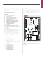
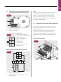
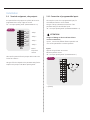
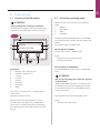
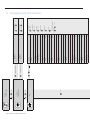
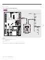
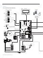
4.3 4.3 Motherboard CS320 Motherboard CS320
Explanation:
X1: Mains connection terminal strip
X2: Motor terminal strip
X3: Terminal strip for command devices
X4: Terminal strip for programmable inputs
X5: Terminal strip for relays
X6: Connector strip for internal ON/OFF switch
X7: Connector strip for internal 3-fold button KDT
X8: Connector strip for LCD monitor
(Beneath the LCD monitor)
X9: No function
X10: Connector strip for brake monitoring module
X11: Connector strip for electronic limit position system
(AWG)
X12: No function
X13: Connector strip for internal 3-fold button CS
X15: Terminal strip for mechanical limit switches (MEC)
X16: Connector strip for BUS system (MS BUS)
X17: Plug-in connector RJ for BUS system (MS BUS)
X18: Connector strip for frequency converter (interface)
X19: Terminal strip for supplying external devices
230V/50Hz
X20: No function
X21: Mains voltage selection
H1: Readyforoperation(green)
Lights up with power supply.
H2: Statusindicator(red)
Lights up with faults or with actuation of the safety
equipment
S1: Programming button (+)
(Beneath the LCD monitor)
S2: Programming button (–)
(Beneath the LCD monitor)
S3: Programming button (P)
(Beneath the LCD monitor)
F1: Fuseprotectionforexternaldevices230V/50Hz
(max. 1A slow-blow)
F2.1: Fuse protection for controller and drive L1 (max. 10 A)
F2.2: Fuse protection for controller and drive L2 (max. 10 A)
F2.3: Fuse protection for controller and drive L3 (max. 10 A)
Terminal strip for protective conductor (PE)
X10
B2
B1
W
V
U
1
2
3
4
5
6
7
8
X5
1
2
3
4
5
6
7
8
X15
1
2
3
4
5
6
7
8
9
10
X4
X7
X6
X12
N
L3
L2
L1
X1
X21
F2.1
F2.2
F2.3
F1
1
2
3
4
5
6
7
8
9
12
11
10
X9
X8
X20
S1
X13
X19
X3
X16
H1
H2
X11
X18
S2
S3
X2
X17
4.3 / 1
NOTE:
ThejumperX4/3-4isfactory-ttedasageneralrule,buthas
no function.

6 – Control CS 320-T / Rev.A 1.01 Control CS 320-T / Rev.A 1.01 – 7
5. Installation
5.1 5.1 Safety instructions for installationSafety instructions for installation
WARNING!
Life-threatening danger due to electric shock!
Before performing wiring work, always disconnect the
Before performing wiring work, always disconnect the
system from the power supply. Make sure that the power
system from the power supply. Make sure that the power
supply remains disconnected during wiring work.
supply remains disconnected during wiring work.
ATTENTION!
Property damage due to improper installation of
the controller!
In order to avoid damage to the controller, observe the
following points:
− Onlyqualiedandtrainedelectriciansmayworkon
electrical systems.
− Switch off the power supply to the system, check that it
is de-energised and safeguard against reconnection.
− Mains cables and control cables must be routed separa-
tely.
− The line types and cross-sections must be selected in
accordancewiththevalidspecications.
− It is essential to observe the local protective regulations.
− Observethespecicationsofthedoormanufacturerfor
installation.
The following points must be correct to guarantee
fault-free functioning:
− The door is installed, fully functional and designed for
power-driven operation.
− Thegearmotoristtedandreadyforoperation.
− Thecommandandsafetydevicesarettedandreadyfor
operation.
− ThecontrolhousingwiththeCS320-Tcontrolleristted.
Observe the valid standards and regulations!
REFERENCE
The instructions from the respective manufacturer must be
observed for the installation of the door, the gear motor and
the command and safety devices.
5.2 5.2 Mains connectionMains connection
Prerequisites
The following points must be correct to guarantee the
function of the controller:
− The mains voltage must correspond with the information
on the type plate.
− The mains voltage must correspond with the voltage of the
drive.
− In the case of three-phase power, this must have a
clockwiserotatingeld.
− Withaxedconnection,anall-polemainswitchmustbe
used.
− With three-phase power, only triple block circuit breakers of
type C (max. 16 A) shall be used.
ATTENTION!
Malfunctions due to improper installation of the
controller!
Beforeswitchingonthecontrollerforthersttimebut
after all of the wiring has been completed, it is necessary
to check all motor connections on the motor and controller
sides. All control voltage inputs are galvanically separated
from the supply.
The control and load lines of the connected drives must be
double-insulated along their entire route.
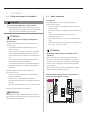
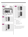
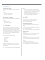
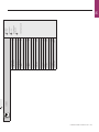
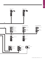
Detailed wiring diagram of mains connection and
motor connection (400 V / 3-phase)
B2
B1
W
V
U
N
L3
L2
L1
X1
X21
F2.1
F2.2
F2.3
F1
X19
X11
X18
X2
M
3
3
400 V / 50 Hz
/ N / PE
5.2 / 1

6 – Control CS 320-T / Rev.A 1.01 Control CS 320-T / Rev.A 1.01 – 7
EN
Detailed wiring diagram of mains connection and
motor connection (230 V / 3-phase)
B2
B1
W
V
U
N
L3
L2
L1
X1
X21
F2.1
F2.2
F2.3
F1
X19
X11
X18
X2
M
3
3
230 V / 50 Hz
/ PE
5.2 / 2
Detailed wiring diagram of mains connection and
motor connection (230 V / 1-phase)
B2
B1
AUF
ZU
N
L
N
X1
X21
F2.1
F2.2
F2.3
F1
X19
X11
X18
X2
M
1
1
230 V / 50 Hz
/ N / PE
5.2 / 3
Explanation:
M1: Motor
X1: Mains connection terminal strip
X2: Motor terminal strip
X11: Connector strip for electronic limit position system
(AWG) with safety circuit
X15: Terminal strip for mechanical limit switches (MEC)
(safety circuit to X2 / B1-B2)
X19: Connection for supplying external devices
Connection:
Connect electronic limit position system (AWG) or Connect electronic limit position system (AWG) or
mechanical limit switch (MEC) to the controller.mechanical limit switch (MEC) to the controller.
Connect controller to the motor.Connect controller to the motor.
Connect controller to the mains network. Connect controller to the mains network.
Secure cable groups with a cable tie directly before the Secure cable groups with a cable tie directly before the
respective terminal.respective terminal.
Check and compare technical data.Check and compare technical data.
➔ “12.Technicaldata“
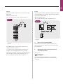
5.3 5.3 Internal fuse protectionInternal fuse protection
ThecontrollerCS320-Tisequippedwithinternalfuse
protection (F2) at the mains input. The fuse elements are
equippedwithnefuses8A/T(5.2x20mm)inthefactory.
N
L3
L2
L1
X1
X21
F2.1
F2.2
F2.3
3
400 V / 50 Hz
/ N / PE
5.3 / 1
ATTENTION!
Malfunctions due to improper fuse protection of
the controller!
Internal fuse maximum 10 A / T!
The internal fuses do not replace fuse protection of the
supply cable. This shall be realised with max. 16 A and must
beconguredastripleblockcircuitbreakersoftypeC.
➔ “5.2Mainsconnection“

8 – Control CS 320-T / Rev.A 1.01 Control CS 320-T / Rev.A 1.01 – 9
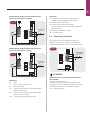
5.4 5.4 Mains voltage selectionMains voltage selection
The position of the bridge connector to X21 must be adjusted
to the supply voltage and motor voltage.
PE
PE
PE
N
L3
L2
L1
X1
X21
3
400 V / 50 Hz
/ N / PE
F2.3
F2.2
F2.1
PE
PE
PE
N
L3
L2
L1
X1
X21
F1
X19
3
230 V / 50 Hz
/ PE
F2.1
F2.2
F2.3
AUF
ZU
PE
PE
PE
L
N
X1
X21
F1
X19
X11
X18
1
230 V / 50 Hz
/ N / PE
F2.1
F2.2
F2.3
5.4 / 1
PE
PE
PE
N
L3
L2
L1
X1
X21
3
400 V / 50 Hz
/ N / PE
F2.3
F2.2
F2.1
PE
PE
PE
N
L3
L2
L1
X1
X21
F1
X19
3
230 V / 50 Hz
/ PE
F2.1
F2.2
F2.3
AUF
ZU
PE
PE
PE
L
N
X1
X21
F1
X19
X11
X18
1
230 V / 50 Hz
/ N / PE
F2.1
F2.2
F2.3
5.4 / 2
PE
PE
PE
N
L3
L2
L1
X1
X21
3
400 V / 50 Hz
/ N / PE
F2.3
F2.2
F2.1
PE
PE
PE
N
L3
L2
L1
X1
X21
F1
X19
3
230 V / 50 Hz
/ PE
F2.1
F2.2
F2.3
AUF
ZU
PE
PE
PE
L
N
X1
X21
F1
X19
X11
X18
1
230 V / 50 Hz
/ N / PE
F2.1
F2.2
F2.3
5.4 / 3
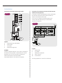
5.5 5.5 Supply to external devices Supply to external devices
(only with 400 V / 3-phase connection)(only with 400 V / 3-phase connection)
TheCS320-Thas2separatevoltagesuppliesforexternal
components, such as signal devices.
X19 230V/1~
X4 24V-DC
N
L3
L2
L1
X1
X21
X19
3
400 V / 50 Hz
max. 1A
230V-AC
max. 500mA
24V-DC
/ N / PE
X4
1
2
3
4
5
6
7
8
9
12
11
10
F1
-
+
L
N
5.5 / 1
NOTE:
Use of the connection X19 is only possible with a supply with
400V / N / 3~.
The connection X19 is protected by the fuse element F1
(max.1A/T).
Installation

8 – Control CS 320-T / Rev.A 1.01 Control CS 320-T / Rev.A 1.01 – 9
EN
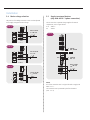
5.6 5.6 Connection of electronic limit position Connection of electronic limit position
system absolute value encoder (AWG)system absolute value encoder (AWG)
5.6 / 1
A
B
A: Absolute value encoder plug
B: AWG plug-in terminal
Connector strip X11 (on connector A)
4 7
grey yellow
5 8
green pink
6 9
white brown
5.6 / 2
Cables with either numbered or
coloured wires are used for the AWG,
depending on the drive:
4 (grey): Safety chain input
5 (green): RS 485 B
6 (white): GND
7 (yellow): RS485 A
8 (pink): Safety circuit output
9 (brown): 12V DC
Connector strip B (only absolute value encoder)
5.6 / 3
C: Thermal element in the drive
D: Emergency manual actuation (emergency crank or
emergency chain)
NOTE:
In order to satisfy the requirements of EN 12453:2017 the
electronic end position system must comply as a minimum
withPL“c”withamin.category2perENISO13849-1.
In order to satisfy this requirement, it is only permissible to
use an absolute value encoder from MFZ (art. no. 97957) as
an electronic end position system.
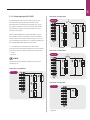
5.7 5.7 Mechanical limit switch (MEC) connectionMechanical limit switch (MEC) connection
Alternatively to the absolute value encoder as an electronic
system, it is also possible to connect a mechanical cam limit
switch and evaluate this.
WithrstcommissioningandafteraRESET,theconnected
limit position system is automatically detected. With a
subsequent change, the respective limit position system must
be selected via a parameter setting in the INPUT operating
mode.
Series STA, MDF05, MTZ05
5.7 / 1
S1
S2
S3
S4
S5
S6

10 – Control CS 320-T / Rev.A 1.01 Control CS 320-T / Rev.A 1.01 – 11
Series MDF20+, KD, MTZ20+
S1
S2
S3 S4 S5 S6
5.7 / 2
Mechanical limit switches
1
2
3
4
5
6
7
8
X15
S2
S5
S1
S6
5.7 / 3
Safety circuit
U
V
W
B1
B2
X2
S3
S4
S7
S8
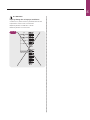
5.7 / 4
Example of connection with 7-wire solution
1
2
3
4
5
6
7
8
U
V
W
B1
B2
X2
X15
S2
S5
S1
S6
S3
S4
S7
S8
5.7 / 5
Legend:
S1 Supplementary limit switch UP
S2 Limit switch UP
S3 Safety limit switch UP
S4 Safety limit switch DOWN
S5 Limit switch DOWN
S6 Supplementary limit switch DOWN
S7 Emergency operation (NC - contact)
S8 Motor thermal protection
NOTE:
In order to satisfy the requirements of EN 12453:2017 the
mechanical limit switches must have been approved as a
“reliablecomponent”inaccordancewithENISO13849-1.
Drives with integrated safety catch device must not be
equipped with mechanical limit switches.
Installation

10 – Control CS 320-T / Rev.A 1.01 Control CS 320-T / Rev.A 1.01 – 11
EN
ATTENTION!
Property damage due to improper installation!
Connection as a 6-wire solution is prohibited and can lead
to destruction of the CS 320-T circuit board.
Reference potential on X2/B1-B2 = 24V-DC
Reference potential on X15=12V-DC
1
2
3
4
5
6
7
8
S3
S4
S7
S8
S2
S5
S1
S6
U
V
W
B1
B2
X2
X15
5.7 / 6

12 – Control CS 320-T / Rev.A 1.01 Control CS 320-T / Rev.A 1.01 – 13
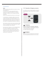
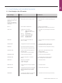
5.8 Connection of command devices
CAUTION!
Risk of injury due to uncontrolled door movement!
A CLOSE command in dead-man operation without a view
of the door is not permitted.
Install the command devices for the dead-man operation
Install the command devices for the dead-man operation
in direct visual contact with the door, although outside
in direct visual contact with the door, although outside
the danger zone for the operator.
the danger zone for the operator.
If the command device is not a key switch:
Install it at a height of at least 1.5 m.
Install it at a height of at least 1.5 m.
Install it where it is inaccessible to the public.
Install it where it is inaccessible to the public.
Command devices (standard)
X3
A
B
C
D
E
5.8 / 1
Legend:
A Button / input DOWN
B Button / input impuls
C Button / input UP
(UP inside, with active two-way control)
D STOP button
E Emergency stop command device
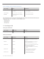
UP / STOP / DOWN switch (6-wire solution)
X3
A
C
D
5.8 / 2
UP / STOP / DOWN switch (4-wire solution)
X3
A
C
D
5.8 / 3
IMPULS button
Function:
UP when door is stationary / STOP with door movement
B
X3
5.8 / 4
- UP switch
- STOP button
Installation

12 – Control CS 320-T / Rev.A 1.01 Control CS 320-T / Rev.A 1.01 – 13
EN
Key switch
A
C
X3
5.8 / 5
Legend:
A Button / input DOWN
C Button / input UP
(UP inside, with active two-way control)
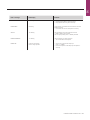
Cover keypad KDT
Push-button with NO / NC contacts.
Up to year of manufacture 12 / 2009.
X7X7
5.8 / 6
J
J Jumper (bridge)
The jumper must be connected if the KDT keypad is not
connected.
Cover keypad CS
Silicone keys with NO contacts.
From year of manufacture 01 / 2010.
X13
5.8 / 7
ON/OFF key switch
NC contact for interrupting the door function (optional).
This switch is part of the safety circuit.
X6X6
5.8 / 8
J
J Jumper (bridge)
The jumper must be connected if the key switch is not
connected.

14 – Control CS 320-T / Rev.A 1.01 Control CS 320-T / Rev.A 1.01 – 15
5.10 5.10 Connection of programmable inputsConnection of programmable inputs
ThecontrollerCS320-Thas3programmableinputs,for
which different functions can be selected.
The type of wiring is determined on the basis of the
parameter settings for the individual inputs.
➔ “10.2Inputoperatingmode“(ParameterEINGANG1–3)
ATTENTION!
Danger of damage to the circuit board due to
incorrect connection!
Inputs 1, 2 and 3 have different reference potentials and
must not be operated from a common potential!
Input 1
Optional wiring with NO / NC contacts.
Reference potential 24V-DC
➔ “10.2Inputoperatingmode“(ParameterINPUT1)
*
X4
5.10 / 1
* optionally
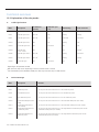
5.9 Terminal assignment, relay outputs
Four potential-free relay outputs are available, which can be
programmed with a variety of types of function.
➔ “10.2Inputoperatingmode“(Parameter RELAY 1-4)
1
2
3
4
5
6
7
8
X5
5.9 / 1
- Relay 1
- Relay 2
- Relay 3
- Relay 4
Internal
relay switch
contacts
There are four potential-free relay outputs able to take a max.
load of 4A at 230 V/1~.
The type of function depends on the parameter setting for the
respective relay output in the INPUT operating mode.
Installation

14 – Control CS 320-T / Rev.A 1.01 Control CS 320-T / Rev.A 1.01 – 15
EN
Input 2
Optional wiring with components on a 8.2 kOhm basis and
NO contacts.
Reference potential 12V-DC
➔ “10.2Inputoperatingmode“(ParameterINPUT2)
*
1
2
3
4
5
6
7
8
9
12
11
10
X4
8K2
5.10 / 2
* optionally
Programmable input 2 is also used as a safety input in
accordance with EN 12453:2017.
Ifaresistancevalueisdetectedwithrstcommissioning
and after a reset, the MOD8 (safety input) is activated
automatically. Individually connected closing edge protective
device 8.2 kOhm must be activated manually in this case.
➔ “5.11SafetyinputperEN12453“onpage17
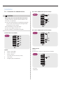
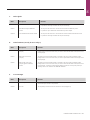
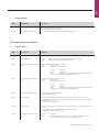
Input 3
Connector strip for optional wiring with pluggable brake monito-
ring module BWM1 or as connection for monitoring an external
load contactor and drive brake.
Reference potential 5V-DC
➔ “10.2Inputoperatingmode“(Parameter INPUT 3)
1
L1
3
L2
5
L3
13
NO
A1
2
T1
4
T2
6
T3
14
NO
A2
1
L1
3
L2
5
L3
13
NO
A1
2
T1
4
T2
6
T3
14
NO
A2
+ 5V
X10
GND
IN
1
2
3
4
*
A
5.10 / 3
* optionally
A Brake monitoring module BWM1
The brake monitoring module is required for drives with a
brake connected (relay 4 / MOD 14-16). The module monitors
the brake function.
B Monitoring an external load contactor and
drive brake (optional)
➔ “5.10/5“
REFERENCE
For a precise description of the function and connection,
refer to the separate documentation for the brake monito-
ring module.

16 – Control CS 320-T / Rev.A 1.01 Control CS 320-T / Rev.A 1.01 – 17
Connection of the brake monitoring module
A
C
B
D
1
2
4
3
1
2
3
4
5
6
7
8
X5
M
X10
XB1
5.10 / 4
Legend:
A Brake monitoring module BWM 1
B Brakerectier
C Drive brake
D Brake power supply (AC)
HINWEIS:
If MOD14-16 (brake actuation) is set on relay 4, the mode for
the brake monitoring module is automatically set at input 3.
Optionally, input 3 can also be used for monitoring an
external load contactor and the drive brake.
The parameter INPUT 3 must then be set to MOD22.
Connection for monitoring an external load contactor
and drive brake (optional)
If the power of the door drive/frequency inverter used exceeds
the maximum load capacity of the internal contactor, an
external load contactor must be used.
In this case, it is possible to monitor the external load
contactor and drive brake with input 3 and therefore
guarantee safe operation.
1
L1
3
L2
5
L3
13
NO
A1
2
T1
4
T2
6
T3
14
NO
A2
61
NO
62
NC
53
NO
54
NC
1
L1
3
L2
5
L3
13
NO
A1
2
T1
4
T2
6
T3
14
NO
A2
61
NO
62
NC
53
NO
54
NC
1
L1
3
L2
5
L3
13
NO
A1
2
T1
4
T2
6
T3
14
NO
A2
+ 5V
GND
IN
X10
61
NO
62
NC
53
NO
54
NC
➞
5.10 / 5
B
A
C
Q1Q2
Legend:
A Brakerectier
B Drive brake
C Brake power supply (AC)
Q1 Mains contactor
Q2 Load contactor
The wiring preparation is carried out in the factory.
Installation

16 – Control CS 320-T / Rev.A 1.01 Control CS 320-T / Rev.A 1.01 – 17
EN
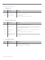
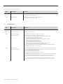
5.11 5.11 Safety input per EN 12453Safety input per EN 12453
Increased requirements on the fail-safety of the slip door
switch have been part of EN 12453 since 2001. With
EN12453:2017 increased safety requirements (PLc, Cat.2)
also apply, for example to slack rope switches and switches
of fall protection systems, including the transmission and
processing of the signal.
With the setting MOD8 the programmable INPUT 2 allows
the evaluation of these components, which all work with an
internal resistance value of 8.2 kOhm. If a fault occurs in one
of the components, the system can no longer be operated and
the message ERROR STOP appears on the display.
1 – 4 components on a 8.2 kOhm basis can be linked
according to the following wiring diagrams. It does not matter
which of the respective switches represents the components
1 - 4 here.
* optionally
CHECK
The tolerance of the individual resistance values must not
exceed max. 1%.
Connection 4 components
1
2
3
4
5
6
7
8
9
12
11
10
X4
8,2 k Ω8,2 k Ω8,2 k Ω
8,2 k Ω
1
2
3
4
5.11 / 1
Connection 3 components
1
2
3
4
5
6
7
8
9
12
11
10
X4
8,2 k Ω8,2 k Ω8,2 k Ω
1
2
3
*
8,2 k Ω8,2 k Ω
1
2
8,2 k Ω
3
5.11 / 2
Connection 2 components
1
2
3
4
5
6
7
8
9
12
11
10
X4
8,2 k Ω8,2 k Ω
1
2
8,2 k Ω
1
*
8,2 k Ω
2
5.11 / 3
Connection 1 component
1
2
3
4
5
6
7
8
9
12
11
10
X4
8,2 k Ω
1
5.11 / 4
* optionally

18 – Control CS 320-T / Rev.A 1.01 Control CS 320-T / Rev.A 1.01 – 19
NOTE:
Withrstcommissioningandafterareset,input2issettoA
(self-teaching) once.
If a resistance value is detected, MOD8 (safety input) is
automatically set and the measured value is stored and
monitored as a reference for the connected safety-related
components.
Deviation of the measured value leads to an error message.
If a safety element is subsequently added or removed, the
resistance measurement must be performed again. For this
purpose the parameter INPUT 2 must be manually reset to A
(self-teaching) and the supply voltage must be switched off
and on again once. Renewed measurement then takes place.
The components used must either comply with EN ISO 13849-1
PLc/Cat.2 or be approved as a reliable component in order to
satisfytherequirementsofEN12453:2017.
Alternatively, the fall protection can also be equipped with an
NC contact and integrated in the safety circuit of the
controller (X3/1-2). This switch with NC contact must be
approved as a reliable component per EN ISO 13849-1. To
ensure cross-wire short monitoring, the connection cable
must be laid in a protective tube.
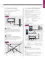
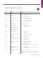
5.12 5.12 Connection of frequency converterConnection of frequency converter
It is possible to connect a Siemens frequency converter for
speed-independent control of the door drive via interface
X18.
X18
5.12 / 1
ATTENTION!
Property damage due to improper installation!
When using a frequency converter, the drive, wiring and
converter module must be compatible.
Please contact technical support.
Please contact technical support.
REFERENCE
For a precise description of the function and connection,
refertotheseparatedocumentationfortheCS320FU.
Installation

18 – Control CS 320-T / Rev.A 1.01 Control CS 320-T / Rev.A 1.01 – 19
EN
5.13 5.13 Connection of LCD monitorConnection of LCD monitor
Full access to all menu settings and parameters of the
controller is possible via the LCD monitor.
➔ “8.Programming“
Plug-in base X8
5.13 / 1
ATTENTION!
Property damage due to improper installation!
The LCD monitor must be plugged in whilst de-energised.
Only an LCD monitor from MFZ (art. no. 91447) may be
used.
ATTENTION!
Property damage due to improper installation!
The MFZ LED module (art. no. 103239) cannot be combined
withtheCS320-T.Useandcommissioningcanleadto
destructionoftheCS320-Tcircuitboard.
5.13 / 2
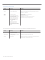
5.14 5.14 Connection of MS BUS componentsConnection of MS BUS components
Two BUS interfaces are present on the circuit board for
connecting different components.
TheMS-BUSLCDmonitor(#121246)issuppliedwitha3m
long connection cable.
The MS-Bus LCD monitor (like the standard LCD monitor)
permits full access to all parameter settings.
It is possible to expand functions or realise additional
functions with the MS BUS function modules.
− ES module: Evaluation of trap-in protection
systems
− I/O module: Input/output expansion
− GV module: Two-way control
Connector strip X16 / X17
B
A
5.14 / 1
C
A ES module Connection to X16 or X17
B I/O module / GV module Connection to X16 or X17
C LCD monitor Connection to X16 only
REFERENCE
For a precise description of the function and connection,
refer to the separate documentation for the BUS modules.
NOTE:
The connector strips X16 and X17 can only be assigned once.
However,multipleBUSmodulescanbeconnectedthrough
special bypass cables.
The current consumption must be considered with this.

20 – Control CS 320-T / Rev.A 1.01 Control CS 320-T / Rev.A 1.01 – 21
20 – Control CS 320-T / Rev.A 1.01
WithrstcommissioningandafteraRESETthefollowing
components are automatically detected and programmed:
− End position system
− Input 2 (safety input)
During this process (approx. 60 seconds) the green LED
ashesandthedisplayshows“PLEASEWAIT…”inthetop
line.
Operation of the system is not possible at this time.
Theendpositionsystemmustbeinstalledbeforerst
commissioning.
Components can be retrospectively changed via the LCD
display or renewed initialisation.
Input 2 remains inactive (OFF), if a resistance value is not
detectedwithrstinitialisation.
Ifaresistorisdetectedatinput2withrstcommissioning,
this is evaluated as a safety element and put into operation as
a safety input.
➔ “10.2Inputoperatingmode“/parameterINPUT2
NOTE:
Initialisation serves not only to teach the different system
components, but also offers the option of changing the menu
language directly.
Thepre-setmenulanguage(ENGLISH)appearsfor
60secondsasashingtextinthedisplay.Withthe[+]and
[–]buttonsitispossibletoselectthedesiredlanguage
andsavethiswiththe[P]button.Alltexts/messagesare
subsequently displayed in the selected language.
6. Initialisation
Page is loading ...
Page is loading ...
Page is loading ...
Page is loading ...
Page is loading ...
Page is loading ...
Page is loading ...
Page is loading ...
Page is loading ...
Page is loading ...
Page is loading ...
Page is loading ...
Page is loading ...
Page is loading ...
Page is loading ...
Page is loading ...
Page is loading ...
Page is loading ...
Page is loading ...
Page is loading ...
Page is loading ...
Page is loading ...
Page is loading ...
Page is loading ...
Page is loading ...
Page is loading ...
Page is loading ...
Page is loading ...
Page is loading ...
Page is loading ...
Page is loading ...
Page is loading ...
-
 1
1
-
 2
2
-
 3
3
-
 4
4
-
 5
5
-
 6
6
-
 7
7
-
 8
8
-
 9
9
-
 10
10
-
 11
11
-
 12
12
-
 13
13
-
 14
14
-
 15
15
-
 16
16
-
 17
17
-
 18
18
-
 19
19
-
 20
20
-
 21
21
-
 22
22
-
 23
23
-
 24
24
-
 25
25
-
 26
26
-
 27
27
-
 28
28
-
 29
29
-
 30
30
-
 31
31
-
 32
32
-
 33
33
-
 34
34
-
 35
35
-
 36
36
-
 37
37
-
 38
38
-
 39
39
-
 40
40
-
 41
41
-
 42
42
-
 43
43
-
 44
44
-
 45
45
-
 46
46
-
 47
47
-
 48
48
-
 49
49
-
 50
50
-
 51
51
-
 52
52


Marantec CS 320 Owner's manual
- Type
- Owner's manual
- This manual is also suitable for
Ask a question and I''ll find the answer in the document
Finding information in a document is now easier with AI
Related papers
-
Marantec CS 320 Owner's manual
-
-
-
Marantec CS 320T Owner's manual
-
-
-
Marantec CS 300 Owner's manual
-
-
Marantec AS 210B Owner's manual
-
Other documents
-
GFA TS 959 Installation Instructions Manual
-
-
CAME MS9502, 818XG-0021 Installation guide
-
Conrad Components 193640 TDR Component 24 V DC 1 - 40 s Operating instructions
-
NIVELCO NIPRESS P6 Installation And Programming Manual
-
Sommer GIGAcontrol A Installation guide
-
BBC Bircher EsMatix 3 User manual
-
Mitsubishi Electric MFZ-KJ35VE User manual
-
-