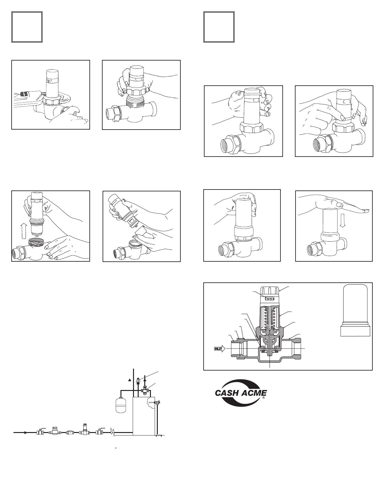
Pressure Indicator
Pressure Reducer Cartridge
Adjustment Knob
Cartridge Nut
Valve Body
Burial Cover
Strainer Screen
O-Ring
Coupling Nut
O-Ring
Union Tailpiece
INLET
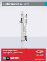
Remove the Pressure Reducer Cartridge by pulling
straight up. (Fig. 8) Clean with cold water only.
Replace the Strainer Screen before re-installing the
Pressure Reducer Cartridge. (Fig. 9) Orient the
Pressure Reducer Cartridge to best view indicator.
Maintenance:
Close isolating valves upstream and
downstream before attempting to
service the valve. Unscrew the
Cartridge Nut. (Fig. 6 and Fig. 7)
4 5
Type EB25, EB25-SS & EB25-400
PRESSURE REDUCING VALVE
For Water Service, with Bronze or Stainless Steel Body
and Inbuilt Back-Pass-Check
2400 7th Ave. SW • Cullman, Al 35055 • www.cashacme.com
Fig. 7
Fig. 12
Fig. 13
Fig. 6
Fig. 9
Fig. 8
Sold Separately
California “Propostition 65” Warning:
This product contains a chemical known to the State of California to cause cancer,
birth defects or other reproductive harm.
Note to Installer/Contractor: California law requires that this notice be provided to the
consumer/end user of this product.
Water
Meter
2000
Series
Ball
Valve
EB-25
Pressure
Regulator
VR-801
Vacuum
Relief
Main
Supply
BF
Backflow
Preventer
Floor
Drain
Cold
Supply to
Fixtures
Tempered
Supply to
Fixtures
Heatguard
110-D
Mixing Valve
NCLX
T&P
Valve
TE Thermal
Expansion
Tank
2000
Series
Ball
Valve
Typical Installation
Schematic
I0445 REV. B
EB25-400 & EB25-SS . . . . . . 20-90 psi
Performance:
Outlet pressure range:
EB25 . . . . . . . . . . . . . . 8-35 or 20-90 psi
Maximum temperature . . . . . . . .180° F
Maximum initial pressure:
EB25-400 . . . . . . . . . . . . 400 psi
EB25 & EB25SS . . . . . . . 300 psi
Service . . . . . . . . . . . . . . . . . Water
Fig. 10
Fig. 11
Orient direct burial cover in such a way that it can
be snapped into position. (Fig. 12 and 13)
Burial Instructions (Optional Cover)
Available for sizes 1/2", 3/4" & 1" only:
Burial Depth should be in accordance
with local plumbing codes.
After valve is installed, reset pressure if necessary,
(see Operation Instructions). Make sure valve is
clean of dirt and debris. Slip provided O-Ring
over cartridge until seated against Cartridge Nut.
EB25 Multi-Cartridge . . 250 psi