Page is loading ...

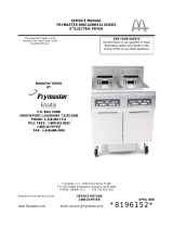
Service Manual
ELECTRIC FRYER with FILTER
MODEL ME14S-C/MFD
MANUFACTURED EXCLUSIVELY FOR
MCDONALD'S®
PITCO FRIALATOR, INC.
P.O.BOX 501 CONCORD, NH 03302-0501
Phone: 1(603)225-6684
Toll Free: 1 (800)258-3708
Fax: 1(603)225-8497
Literature # L20-139 Rev 1 Rev Date 1/98 Made in the United States of America

NOTICES
There are three different types of notices that you should be familiar with, a NOTICE, CAUTION, and WARNING.
A NOTICE is a special note used to call attention to a particularly important point. CAUTION is used to point out a
procedure or operation which may cause equipment damage. The WARNING notice is the most important of the
three because it warns of an operation that may cause personal injury. Please familiarize yourself with your new
cooker before operating it and heed the notices throughout this manual. The WARNINGS are listed below and on
the following page for your review prior to operating the unit.
FOR YOUR SAFETY
DO NOT store or use gasoline or other flammable vapors or
liquids in the vicinity of this or any other appliance.
WARNING:
Improper installation, adjustment, alteration, service or
maintenance can cause property damage, injury or death. Read
the installation, operating and maintenance thoroughly before
installing or servicing this equipment.
THIS MANUAL MUST BE RETAINED FOR FUTURE REFERENCE

SAFETY SAFETY SAFETY SAFETY SAFETY
WARNING
The fryer must be electrically grounded in accordance with local codes. If local codes do not apply follow the
requirements of National Code ANSI/NFPA 70-1990
WARNING
Before connecting any fryer make sure that all the circuit breakers for the appliance(s) are OPEN or OFF.
NEVER connect the fryer with power applied to the power lines. Some appliances have more than one power
supply. Make sure they are ALL disconnected.
WARNING
The heating elements MUST be covered with water or oil before they are turned on. NEVER turn on the fryer
unless the elements are covered by at least one inch of liquid. For the Element Bum OFF Procedure refer to the
operation manual.
WARNING
Never melt blocks of shortening on top of the heating elements. This will cause a fire, and void your warranty.
WARNING
Water and shortening DO NOT mix. Keep liquids away from hot shortening. Dropping liquid frozen food into
the hot shortening will cause violent boiling.
WARNING
At operating temperature the shortening temperature will be greater than 300°F. Extreme care should be used
when filtering operating temperature shortening to avoid personnel injury.
WARNING
Follow the filtering procedures carefully when filtering, these can be found in the operating manual. Before
handling any parts after filtering make sure they have cooled to room temperature.
WARNING
All power supplies must be disconnected before servicing. Some appliances have more than one power supply.
Make sure they are ALL disconnected.
WARNING
DANGER - HIGH VOLTAGE PRESENT
NEVER remove the entrance box cover unless all power to the appliance has been disconnected.
SAFETY SAFETY SAFETY SAFETY SAFETY

Table of Contents
Table of Contents i
Warranty Statement 1
Chapter 1: INSTALLATION INSTRUCTIONS 2
Ventilation 2
Clearances 2
Once the fryers are in place 2
Filling the fryer with oil 3
Set Up 3
Shut Down 3
Chapter 2: HOW DOES IT WORK? 4
Heating System 4
Hi -Limit System 4
Filter System 5
Hood Relay System 5
Chapter 3: COMPONENT TROUBLESHOOTING 5
Probe 5
Relays 6
Hi Limits 6
Drain Valve & Return Valve Switches 6
Transformer 6
Elements 6
Contactor 6
Chapter 4: TROUBLESHOOTING 7
Fryers 7
Filters 8
Chapter 5: COMPONENT CHANGEOUT 8
Probe 9
Hi Limit 9
Elements 9
Components mounted in the front panel 9
Heat Demand Relays 10
Circuit Breaker 10
Hood & Filter Relays 10
Control relays 11
Proximity Switches 11
Filter Pumps 11
Chapter 6: PARTS 12
Operational Components 12
Filter 12
Miscellaneous 13
Accessories 13
Wiring Harnesses 13
Chapter 7: Parts Identification 14
Chapters 8: Schematics 15
i

WARRANTY STATEMENT
Pitco Frialator, Inc. makes the following limited warranties to
the original purchaser only for this equipment and replacement
parts:
1. WARRANTY PROVISIONS - FRYERS
A. Pitco Frialator, Inc. warrants all parts, with the
exception of the frypot, elements and computer for 1
year after the date of installation of the fryer.
B. If any parts become defective during the first year
after the installation date, Pitco Frialator will also pay
for the labor, freight and travel costs involved in
replacing said part.
2. WARRANTY PROVISIONS - FRYPOTS
A. If a frypot develops a leak due to a defect in material
or workmanship within the first 10 years after
installation, Pitco Frialator, Inc. will either weld or
replace, at its discretion, the frypot.
B. The customer will be responsible for all freight, labor
and travel charges for this repair, except within the
period stated in section 1-B.
3. WARRANTY PROVISIONS - COMPUTER
A. Pitco Frialator, Inc. will warrant the Intelli-fry
Computer from defects in material or workmanship
for a period of two years.
B. If the computer is found to be defective during the
first 2 years after the installation date, Pitco Frialator
Inc. will also pay for the labor, freight and travel costs
involved in replacing said part.
4. WARRANTY PROVISIONS - ELEMENTS
A. Pitco Frialator, Inc. will warrant the Electric Elements
from defects in material or workmanship for a period
of 3 years.
B. The customer will be responsible for all freight, labor
and travel charges for this repair, except within the
period stated in section 1-B.
Retain this manual for future reference.
l

INSTALLATION INSTRUCTIONS
CAUTION:
This equipment is manufactured for the use on a
particular voltage and phase which is specified on the
rating plate located on the inside of the door.
When your fryers arrive, look them over carefully
noting any damage on the freight bill. If concealed
damage is found after you have accepted the equipment,
report it to the carrier immediately as all claims must be
filled within 15 days of the receipt of the shipment.
Also, be sure to keep all packing materials as these will
be necessary to make any claim.
Follow these installation instructions carefully. A proper
installation is important for the operation of the fryers.
All installations must conform to all local and state
codes and well as the United States National Electrical
Code (ANSI/N.F.P.A. No. 70-1987). In Canada,
installations must be made in accordance to Canadian
Electrical Code Part I, CSA-C22.1.
Do not block the area around the casters and under the
fryers. Contact the Authorized Pitco Frialator rep-
resentative for any service related problems. Routine
maintenance may be performed by qualified personnel.
The duct system, the hood system and the fryers must be
cleaned on a regular basis and must be kept clear of any
grease build up. See the appropriate Maintenance
Requirements Cards.
Ventilation;
A proper ventilation system is also an important part of
the installation. For information on the construction and
installation of ventilating hoods, please see "Standard
for the Installation of Equipment for the Removal of
Smoke and Grease Laden Vapors from Commercial
Cooking Equipment", N.F.P.A. No. 96-1987. Copies
can be obtained by writing to the National Fire
Protection Association, Battery March Park, Quincy,
MA 02269
Clearances:
Minimum clearance of 6" (15cm) must be maintained from
combustible construction on each side and the rear of the
equipment. This equipment may be installed on combustible
floors.
Maintain a minimum of 24"(61cm) clearance in front of the
fryer to provide for proper operation, maintenance and
servicing.
Wiring diagram(s) are located in the back of the service
manual and inside the fryers.
The control (interlock) voltage for this equipment must be
120 VAC (US & Canada). For other countries please check
the rating plate.
Regular cleaning of this equipment, as well as the hood, is
an important part of proper maintenance. Refer to
Maintenance Requirement Cards for proper procedure and
frequency.
Once the fryers are in place:
Leveling the fryers will help ensure proper operation. To
level the fryers loosen the two set screws on the caster stem.
Rotate the collar of the caster to raise or lower the height of
the unit. Tighten set screws to lock the adjustment. Casters
should be adjusted so that the fryers are level and at the
correct height under the hood system.
Clean the fry tanks using the Boil Out procedure on
Maintenance Card 14A.
A wiring diagram is located in the back of this manual and
inside the fryers.
EQUIPMENT SET UP AND SHUT DOWN
PROCEDURES
NOTE: Should you experience a power failure, your fryers
will shut off automatically. Once the power has been
restored, press the key to turn the fryer back ON. If the
machine is being filtered, close the RED return valve so that
the filter does not run if the machine is left unattended. Do
not attempt to restart the fryers until the power is restored.
2

Filling the fryer with oil;
It is very important to make sure the oil level is cor-
rect before attempting to heat shortening in your
Pitco fryer.
Liquid shortening can be poured directly into the fry
tank until the correct level has been reached. This is
indicated by a line on the right hand side of the in-
side of the tank.
NOTE: The "C" (Cold) level is considered to be the
"MINIMUM" oil level and the "H" (Hot) level is
considered to be the "MAXIMUM" oil level.
For solid shortening, the shortening must be cut into
small blocks about 1" (2.54 Cm) in size. These
small blocks must be placed under and around the
heating elements.
The fryer can now be turned ON.
Set-Up:
NOTE: Please read the Operating instructions thor-
oughly before attempting to operate this equipment.
Make sure the power cords are plugged into the cor-
rect receptacles and the proper building circuit
breakers are turned ON.
Press the key on either side of the full vat com-
puter, or the right key for the right side and the
left key for the left side of a split vat computer to
turn the unit ON.
The computer display will light and the heating ele-
ments will begin to heat and will be controlled by
the computer/controller.
NOTE: From a cold start the fryer will automati-
cally begin a melt cycle. This is a condition where
the computer will heat the shortening in small con-
trolled bursts of heat. Once the predetermined tem-
perature has been reached, the unit will exit the melt
cycle and go to normal operation. The melt cycle
cannot be overridden.
Make sure that the shortening is at the proper level
after cooking temperature has been reached. It may
be necessary to add shortening to maintain the
proper level.
NOTE: When adding solid shortening to an
empty fry tank, first remove the baskets and
support racks and fill the bottom of the tank with
shortening, continue to pack the remaining
shortening into the tank. Place the basket support
rack on top of the shortening before turning the
unit ON. For liquid shortening fill to the level
lines indicated on the side of the tank.
Shut Down;
Press the corresponding key to turn the fryer
OFF. The Computer display will show "OFF" and
all heating functions will cease.
NOTE: When the fryer is not being used, place
the cover over the fry tank.
3

Chapter 1: HOW DOES IT WORK?
The McDonalds Electric fryer will have certain reactions
to what is happening, knowing what these reactions are
and knowing what the machine is trying to do will enable
us to diagnose most of the problems likely to be
encountered.
Heating System
Power to the machine is turned ON:
The computer is supplied with 24VAC and, if the Drain
Valve Handle is closed, the Proximity Switch (S3) will
supply 24 VAC to the DVI (Drain Valve Interlock) Input
at the computer. The computer is turned ON:
The first computer in the "battery" of fryers (this includes
either side of a split vat) to be turned ON will
energize a Relay (K15) that will turn the Hood system ON.
The Power On Relay (K2) will be energized, closing the
circuit. If the Hi Limit (S1) is NOT tripped the Safety
Contactor (K10) will energize. Computer calls for heat:
The Heat Demand Relay (K1) will energize supplying the
Heat Demand Contactors (K4, K5 & K6) with 24 VAC.
This will also supply the computer with a heat feedback
signal.
Hi Limit System;
When the Hi Limit (S1) trips it causes the Relay (K3) to
energize opening the supply voltage circuit to the Safety
(K10) and Heat Demand (K4, K5 & K6) Contactors. This
Relay (K3) has a loop circuit that will cause it to stay
energized until the Hi Limit (S1) resets and the power to
the machine is turned OFF and back ON again.
4

Filter System:
Opening the RED Return Valve Handle will
cause the Pump On Relay to be energized and
the pump will begin to pump. Closing the
Return Valve Handle will de - energize the
Relay and the Pump will stop pumping.
Hood Relay System;
There is one Hood Relay (K15) per "battery" of
fryers, it is wired in parallel to every computer
(both sides of a split vat). When any side of any
computer is turned ON this Relay (K15) will
energize and will stay energized until all of the
computers are turned OFF.
Chapter 2: COMPONENT
TROUBLESHOOTING:
Probe;
The resistance of the probe will change as the tem-
perature changes. The resistance will decrease as the
temperature rises. The lower the temperature the greater
the resistance change will be per degree of temperature
change, as the temperature approaches the working range
of the probe, the resistance change will become more
linear.
If the probe is suspect, check its resistance and the oil/air
temperature at which it was taken. Compare these values
on the chart below.
TEMP
RESISTANCE
TEMP
RESISTANCE
°F Ohms °F Ohms
60 139055 330 1192
80 84644 335 1123
100 53146 340 1058
120 34328 345 998
140 22755 350 942
160 15446 355 890
180 10716 360 841
200 7586 365 795
210 6427 370 752
220 5470 375 712
240 4013 380 675
260 2991 385 640
280 2262 390 607
300 1734 395 576
320 1347 400 547
325
1267
If the probe returns an open circuit or 0 Ohms reading it
should be replaced. If the resistance varies more than 20
Ohms when being checked between 325-375°F the probe
will give a false temperature reading on the computer and
should be replaced. However, it will continue to operate
at a slightly higher or lower temperature. Allow the oil to
cool and check the probe resistance at a lower
temperature. As can be seen from the chart a greater
degree of offset can be allowed at a lower temperature.
5

Relays:
The Heat Demand and Hood relays are 24VDC relays and
will energize when the correct voltage is supplied to the
coil. When energizing, the relay Switching Contacts will
close, thus connecting the Common and Normally Open
terminals. The Hi -Limit relay is a 24 VAC relay and may
be checked in the same manner as the above relay.
Hi Limits:
A Hi - Limit switch is a normally closed switch until the
temperature at the probe reaches 435 ± 15°F. In order to test
this switch it will be necessary to bypass the Heat Demand
Relay. Refer to Page 7 of the Operating Manual for
instructions on how to perform this test.
WARNING
Do NOT leave the machine during this test. This test will
cause the oil to heat past the normal operating temperature
and can cause damage to the machine and its operator.
If the switch does not trip between the prescribed limits it
is defective and should be replaced. Once tripped, the
switch will not reset until the oil has cooled to
approximately 400°F. If the switch does not reset it is
defective.
Drain Valve & Return Valve Switches;
This switch is a magnetically operated Reed switch. When
the Drain Valve handle is moved to the open position, the
Actuator will move away from the switch causing the Reed
switch to open. When the Drain Valve is closed the Reed
switch will close. This switch can also be checked with an
Ohm meter. The normal gap between the Actuator and the
Sensor switch on the Drain Valve handle is 1/8" - 1/4" (3 -
6mm).
Transformer;
Transformers are multiple input voltage 24 volt output
voltage and can be checked by reading the input and
output voltages.
Elements;
Each Element has three coils inside it, check all ele-
ment coils with an Ohm Meter, the resistance should
correspond to the chart below, if the resistance varies
more than 5 Ohm the element will need to be changed.
Also check for continuity to ground on each end of the
suspect element, there should be no continuity to
ground.
208 volt elements 18.5 Ohms
220 volt elements 20.7 Ohms
240 volt elements 24.6 Ohms
Contactor:
Check the coil with an Ohm Meter, the resistance
should be approximately (400 Ohms), if it does not
have this resistance it should be changed.
6

Chapter 3: TROUBLESHOOTING GUIDE
Fryers:
PROBLEM POSSIBLE CAUSE ACTION
Computer will NOT turn ON A. No power to the machine A. Check building circuit breaker
Display does NOT light B. F1 Fuse is blown Check power cord is plugged in
C. T1 Transformer B. Check Fuse F1 .replace if defective
C. Check voltage In & Out of TI
Computer comes ON, Hood system does
NOT
A. Hood relay A. Check & replace if defective
Computer shows "IGNITION" A. Hi Limit tripped A. If oil is below 400°F, reset Hi Limit
"FAILURE" and machine does B. Safety contactor replace if defective. If oil is above
NOT heat C. Heat Demand relay 400°F, allow to cool and try to reset
D. Hi Limit relay B. Check & replace if defective
E. Power On relay C. Check & replace if defective
F. Heat Demand relay D. Check & replace if defective
G. Elements E. Check & replace if defective
F. Check & replace if defective
G. Check & replace if defective
Machine is heating slowly A. Heat Demand relay A. Check & replace if defective
B. Element B. Check & replace if defective
C. Loss of power on 1 leg of C. Check input power, repair or call
3 Phase input power Authorized Electrician
Oil is Colder or Hotter than A. Probe A. Check & replace if defective
computer/controller registers B. Probe wiring terminals B. Clean or repair
Computer display shows A. Green Drain valve not fully A. Check position of handle
"DRAINING" or "TURN OFF" closed B. Switch may be loose or have
B. Sensor switch loose wires
C. Incorrect switch gap C. Check gap, replace if defective
Elements do not stay down or A. Spring tension A. Check & adjust
seem to float or are stuck in up B. Lock handle may be stiff or B. Loosen & lubricate
position seized

Filters:
PROBLEM PROBABLE CAUSE CORRECTIVE ACTION
Red Return Valve is open but no A. Red Return Valve NOT fully open A. Pull slightly on the Red handle to check
pump sound can be heard B. Filter Circuit Breaker may be tripped that it is fully open.
C. Filter Motor Thermal Overload may B. Locate the circuit breaker and reset.
be tripped C. Push Red reset button located on end of
D. Sensor switch may be loose or filter motor.
defective D. Check that the switch is tight in its
mounting. If switch is bad replace it.
Drain valve is closed and the A. Green Drain Valve is NOT fully A. Apply a little more pressure to the
computer has been reset but Closed Green Handle to check that it is
still shows "DRAINING" or B. Sensor switch may be loose or bad fully closed.
"TURN OFF"
B. Check that the switch is tight in its
mounting. If switch is bad replace it.
Drain Valve is OPEN, the oil A. Green Drain Valve is NOT fully open A. Apply a little more pressure to the
is draining slowly or not at all. B. Drain is plugged with debris Green Handle to check that it is fully
open.
B. Use the Clean Out Rod from inside the
Fry Vat to clear the Drain Valve. If this
does NOT clear the blockage, CLOSE
the Green Drain Valve and follow these
instructions for clearing the main drain
line.
CAUTION:
Some HOT oil may still come out when
the cap is removed.
Remove the two screw from the end
cap (Do NOT lose these.) Use the
Clean Out Rod to clear the main drain
tube. Install the end cap along with its
gasket and two screws. Do not
overtighten these screws.
8

Chapter 3: COMPONENT CHANGEOUT:
Probe:
1. Remove the rear housing cover.
2. Disconnect the wiring connector.
3. Push the pins/sockets out of the connector.
4. Remove the 2 probe brackets.
3. Disconnect the 2
wires from the connections on the
Hi Limit.
4. Remove the 2 probe brackets.
5. Remove the Hi Limit Bulb bracket.
6. Gently remove the rubber grommet from around
the capillary of the Hi Limit.
7. Pull the Hi Limit up through the hole. Install in the
reverse order.
Elements:
1. Remove the rear housing.
2. Remove the 2 probe brackets.
3. Remove the Hi Limit Bulb bracket.
4. Remove the element rack.
5. Using a suitable cutting tool, cut the appropriate
wires at the yellow crimped connections.
6. Pivot the elements up so that the mounting screws
are exposed, remove the 2 mounting screws.
7. Pull the element out of the pivot assembly and
feed the wires through the hole.
Install in the reverse order.
Components mounted in the front panel:
To access all of the components mounted in the front
panel, remove the 2 screws at the top of the com-
puter/controller.
9
5. Pull the probe down through the rubber grom-
met.
Install in the reverse order.
Hi Limit:
1. Remove the rear housing.
2. Remove the 2 mounting screws.

Pivot the front panel down and allow the computer to be
supported on the mounting tabs.
Unplug the computer/controller wiring harness. The front
panel can now be removed by pulling the complete
assemby forward.
Remove the lower cover by removing the 2 screws
located in the bottom of the cover.
All of the components mounted in the front panel can now
be accessed through the opening.
Heat Demand Relays;
Mounted on the rear brace of each fryer unit you will find
the Heat Demand Relay housing. Remove the cover of the
housing from the front of the machine. The Relays can
now be seen from the front, they are mounted to the Heat
Sink using 2 screws. Terminals 1 & 2 are the load
connections and terminals 3 & 4 are the 24 VAC input
terminals.
Circuit Breaker:
Remove the mounting screws on either side of the cover.
Turn the cover over and the circuit breaker can be removed
from the cover.
Hood & Filter Relays;
These relays are always wired in the following manner -
10

Control relays are always wired in the following manner -
Proximity Switches:
1. The actuator can be removed by removing the 2
mounting screws.
the wiring harness and by removing the 2 mounting
screws.
Install in the reverse order.
Filter Pumps:
1. From the front of the machine, pull the ring back on
each of the 2 quick disconnects and release the
couplings.
2. Remove the 2 screws, and the front of the Pump/
Motor assembly will drop. The assembly can be
removed from the machine by lifting the rear slightly
and pushing back. The front of the mount can be
lowered until the assembly can be removed from the
machine.
Install in the reverse order.
2. The sensor may be removed by disconnecting
Control Relays:
11

Chapter 5: Parts
Operational Components:
Part Schematic Description
Number Nomenclature
PP11162 A1 Computer/Controller
PP11018 RT1 Probe
PP11007 HR Element, 208V
PP11008 HR Element, 220V
PP11009 HR Element, 240V
PP11010 S2 Hi Limit
PP11058 K1 Relay, Heat Demand
PP11033 K3 Relay, Hood System
PP11011 K4-K9 Relay, Elements
PP10560 K10, K14 Contactor 24 VAC
PP10210 T Transformer, 40VA
PP10429 T Transformer, 80VA
PP10262 S3 Proximity Switch, Sensor
PP10263 S3 Proximity Switch, Actuator
P5045720 F2 Fuse, 4 Amp Slow Blow
Filter:
PP10101 Motor B6638401 Tee, Drain - 1 1/4" end
PP10417 Pump Only B6610702 Tee, Drain - Middle
PP10416 Motor Only B6638402 Tee, Drain - 1" end
B6638601 Motor Assembly with Hoses etc B6638501 Tee, Drain - Split to Split
B6602417 Filter Hose, Outlet 6" A6699601 Tube, Drain - Split
P6071122 Quick Disconnect, Female A6699603 Tube, Drain - Split to Full
PP10262 Proximity Switch, A6699605 Tube, Drain - Full to Full
PP10263 Proximity Switch, Actuator A6643901 Retainer, Drain Elbow
PP10058 Relay, Filter A7001701 Bracket, Drawer Roller Mount
PP10460 Circuit Breaker P6071123 Quick Disconnect, Male
PP11138 Gasket, Drain Line End B4002001 Handle, Return Valve LH
PP11172 Clamp, Band B4002002 Handle, Return Valve RH
PP10034 Clamp, Drain Line P6071780 Valve, Ball 3/8"
PP10032 Gasket PP11181 Gasket, Drain End
B6641101 Filter Pan Assembly PP11182 Gasket, Tee Clean Out
B6640801 Filter Drawer Assembly A7000101 Seal, Drain Line
B6641001 Lid, Filter A7004401 Cover, Tee Clean Out
P6071516 Handle, Lid A6643701 Thumb Screw
B6640901 Retainer, Paper B6641701 Pipe Drain Extension
A7001202 Support, Paper A1103302 Basket Hanger
PP10409 O-Ring PP10739 T-stat Snap Disk 135F open -105F close
B6641501 Elbow, Drain Assembly
12

Miscellaneous:
Wiring Harnesses:
B3402301-C Tank, Full Vat B6726501 Harness, Diode with Diode
B3402501-C
Tank, Split Vat
B6726601
Harness, Control - Full Vat
B2800902-1
Element Rack - Split Vat
B6726801
Harness, Hi Power - Full Vat
B2800901-1
Element Rack - Full Vat
B6726901
Harness, Hi Power - Split Vat
PP10814
Caster, 9" Non Lock
B6728201
Harness, SV First Pos with Hood
B2302301
Door, LH
B6728301
Harness, Filter Option
B2302302
Door, RH
B6730501
Harness, Hi Limit
A3802901
Hinge, Top
B6730601
Harness, Circuit Breaker
A3802903
Hinge, Bottom
B6728001
Harness, Filter Pump
B3801301
Hinge Rod, Door
PP11046
Hinge, Element Pivot – Split Vat
PP11045
Hinge, Element Pivot - Full Vat
PP11006
Handle, Door
P6071305
Magnet Catch
PP10368
Drain Valve - Full Vat
P6071769
Drain Valve - Split Vat
A1404402
Clamp, Hi Limit Bulb
A1404002
Clamp, Probe - Split Vat
A1404102
Clamp, Probe - Full Vat
A1404202
Clamp, Probe - Rear Split Vat
A1404302
Clamp, Probe - Rear Full Vat
B4001601
Handle, Drain Valve - Full Vat
B4001701
Handle, Drain Valve - Split Vat L
B4001702
Handle, Drain Valve - Split Vat R
A4015801
Handle, Lever Stop Release
B2602701
Handle, Lift - Split Vat
B2602702
Handle, Lift - Full Vat
PP11059
Plunger
B2100904
Cover - Full Vat
B2100901
Cover - Split Vat
P6071516
Handle, cover
PP11051
Power Cord, with 15-60P Plug
PP11157
Cord, 5 wire with #65 Plug
PP11042
Cord, 5 wire with L21 -20P Plug
P6071636
Spring, Tension
P6071226
Grommet, 0191 x 113 x 088
P6071221
Grommet, 0131 x 075 x 056
P6071228 Grommet, 1703 x 25 x 2
Accessories:
B2100902
Cover - Full Vat
B2100901
Cover - Split Vat
A1907002
Channel Strip
13

Chapter 6: Parts Identification
Computer/Controller
PP11162
Element
PP11007, PP11008, PP11009
Contactor, Safety
PP10560
Probe
PP11018
Relay, Heat Demand
PP11068
Relay, Hood System
PP11033
Transformer
PP10210 & PP10429
Proximity switch. Sensor
PP10262
Proximity Switch, Actuator
PP10263
Motor, Filter
PP10101
Quick Disconnect
P6071122 (Female)
P6071123(Male)
Relay, Filter
PP10058
Circuit Breaker
PP10460
Gasket, Clean Out Port
PP11182
Gasket, Drain Line
PP10032
Clamp, Band
PP11172
Valve, Ball 3/8"
P6071780
14
Relay, Element
PP11011

Chapter 7 : Schematics
Schematic Description Drawing Number
McDonalds, Electric - Domestic ..................................................................... 700246
15

/