Page is loading ...

1
These instructions must be left with the user
Mira Vision
Installation Guide

2
CONTENTS
Introduction ................................................................................................3
Products Covered by this Guide...........................................................3
Guarantee ............................................................................................3
Patents and Design Registration ..........................................................3
Important Safety Information .....................................................................4
Pack Contents ...........................................................................................6
Specications ............................................................................................9
Standards and Approvals .....................................................................9
Dimensions .............................................................................................. 11
Installation ...............................................................................................12
General ...............................................................................................12
Important Information Regarding Radio Controlled Devices .............. 12
Installation Schematic ........................................................................16
Position and Signal Test ..................................................................... 18
Shower Fittings - Ceiling Fed .............................................................21
Shower Fittings - Rear Fed ................................................................24
Wireless Controller ............................................................................ 28
Commissioning ........................................................................................ 29
Re-Registering ........................................................................................31
Fault Diagnosis ........................................................................................32
Maintenance ............................................................................................ 36
Spare Parts .............................................................................................37
Accessories .............................................................................................40
Disposal and Recycling ...........................................................................41
Notes .......................................................................................................42
Customer Service .................................................................................... 44
If you experience any difculty with the installation or operation
of your new shower, then please refer to the Fault Diagnosis section,
before contacting Kohler Mira Ltd.
Our telephone and fax numbers can be found in the back of this guide.

3
Thank you for purchasing a quality Mira product. To enjoy the full potential of your
new product, please take time to read this guide thoroughly. Having done so, keep
it handy for future reference.
The Mira Vision Mixer Valve is designed to be used with the Mira Vision showerhead
and ttings.
Products Covered by this Guide
Mira Vision Digital Mixer - High Pressure/Combi Valve
Mira Vision Digital Mixer - Pumped Valve.
Mira Vision Wireless Controller.
Mira 360 Fittings (Ceiling Fed or Rear Fed).
Guarantee
For domestic installations, Mira Showers guarantee the Mira Vision against any defect
in materials or workmanship for a period of ve years from the date of purchase
(shower ttings for one year).
For non-domestic installations, Mira Showers guarantee the Mira Vision against any
defect in materials or workmanship for a period of one year from the date of purchase.
For terms and conditions refer to the back cover of this guide.
Recommended Usage
Domestic
Light Commercial
Heavy Commercial
Healthcare
Patents and Design Registration
Design Registration 001295935
Patents GB: 2 421 297
USA: 7 669 776
Patent Applications WO: 2009/022112
EUROPE: 2 227 647
USA: US-2010 - 0282 326 - A1
CHINA: CNI01918743A
INDIA: 1306/MUMNP/2010
INTRODUCTION

4
IMPORTANT SAFETY INFORMATION
Warning!
Follow all warnings, cautions and instructions contained in this guide, and
on or inside the appliance.
1. THIS APPLIANCE MUST BE EARTHED. ENSURE SUPPLEMENTARY
BONDING COMPLIES WITH THE “REQUIREMENTS FOR ELECTRICAL
INSTALLATIONS”. The Mira Digital Mixer Valve is intended to be permanently
connected to the xed electrical wiring of the mains system. A means for electrical
isolation of the appliance shall be provided in the xed wiring in accordance with
local wiring regulations.
2. Products manufactured by us are safe and risk-free, provided that they are
installed, used and maintained in good working order, in accordance with our
instructions and recommendations.
3. Isolate the electrical and water supplies before connecting to the appliance.
4. This appliance must be provided with means for disconnection that is incorporated
into the xed wiring in accordance with the relevant local wiring regulations.
5. Refer to the wiring diagram before making any electrical connections.
6. Mains connections are exposed when the cover of the Digital Mixer Valve is
removed.
7. The Digital Mixer Valve must not be installed where it can become frozen.
8. Make sure that any pipework that could become frozen is properly insulated.
9. In accordance with BS7671 a 30mA Residual Current Device (RCD) should
be included in the electrical circuit. This may be part of the consumer unit or a
separate unit.
10. All pipework must be checked for leaks before the product installation is
completed. The product should be pressurised and both inlet & outlet connections
inspected.
11. If the shower is dismantled during installation or servicing then upon completion
the product must be inspected to ensure all electrical connections are tight and
that there are no leaks.
12. Having completed the installation, make sure that the user is familiar with the
operation of the appliance.
13. DO NOT commission this appliance if water leaks from the unit.
14. Only Mira recommended outlet ttings should be used.
15. Ensure all electrical connections are tight, to prevent overheating.
16. This product is not suitable for areas with high humidity (i.e steam rooms).
Please consult your installer.
17. The water supplies to this product must be isolated if the product is not to be
used for a long period of time. If the product or pipework is at risk of freezing
during this period they should also be drained of water.

5
Caution!
1. Read all of these instructions and retain this guide for later use.
2. The electrical installation must comply to “BS 7671 - Requirements for Electrical
Installations” commonly referred to as the IEE Wiring Regulations, or any
particular regulations and practices, specied by the local electricity supply
company.
3. The plumbing installation must comply with the requirements of UK Water
Regulations / By-laws (Scotland), Building Regulations or any particular
regulations and practices, specied by the local water company or water
undertakers.
4. Make sure that you fully understand how to operate this shower and make sure
that it is properly maintained in accordance with the instructions given in this
manual.
5. Children should be supervised to make sure that they do not play with the
appliance.
6. Anyone who may have difculty understanding or operating the controls of the
shower should be supervised whilst showering.
Particular consideration should be given to:
• The young
• The elderly
• The inrm
• The disabled
• Anyone who suffers from a medical condition that can result in
temporary incapacity (e.g. Epilepsy or blackouts).
• Anyone inexperienced in the correct operation of the controls.
7. The appliance is not intended for use by persons (including children) with reduced
physical, sensory or mental capabilities, unless they are supervised or have been
given instruction concerning the use of the appliance by a person responsible
for their safety. Sunburn or skin conditions can increase your sensitivity to hot
water. Make sure that you set the shower to a cooler temperature.
8. If any of the following conditions occur, isolate the electricity and water supplies
and refer to section ”To contact us”, in the back cover of this guide.
• If the cover is not correctly tted and water has entered the appliance case.
• If the case is damaged.
• If the appliance begins to make an odd noise, smell or smoke.
• If the appliance shows signs of a distinct change in performance, indicating
a need for maintenance.
9. DO NOT operate if water leaks from the appliance.
10. DO NOT operate this appliance if it is frozen. If suspected of being frozen, isolate
and contact us for advice.

6
Digital Mixer Valve
Wireless Controller
3 x Fixing Screws
2 x Fixing Screws
2 x Wall Plugs
Digital Mixer -
High Pressure/Combi Valve
Digital Mixer - Pumped Valve
2 x Push-Fit Isolators
3 x Wall Plugs
1 x Outlet
Connector
1 x Wireless
Controller
1 x Wall Plate
3 x AA Batteries
OR
PACK CONTENTS
Tick the appropriate boxes to familiarise yourself with the part names and to conrm
that the parts are included.
Documentation
1 x Wireless Controller User Guide
1 x Showerhead User Guide
1 x Customer Support Brochure
1 x Battery Cover

7
Ceiling Fed Fittings
1 x Installation Template
1 x Ceiling Plate
1 x Showerhead
1 x Extension
1 x Slide Bar
Assembly
2 x Brackets
2 x Hex Screws
2 x Wall Plugs
2 x 45mm Screws
2 x 70mm Screws
1 x Hex Key
1 x Elbow Kit
2 x Spacers
2 x Rubber Washers
1 x Hose
1 x Plastic Pipe

8
2 x Hex Screws
2 x Wall Plugs
2 x 45mm Screws
1 x Hex Key
1 x Installation Template
2 x Rubber Washers
1 x Right Angle
Connector (RAC) Kit
1 x Right Angle
Connector Shroud
1 x Hose
2 x Brackets
1 x Slide Bar
Assembly
2 x End Plugs
1 x Showerhead
Rear Fed Fittings

9
SPECIFICATIONS
Standards and Approvals
The Mira Vision complies with all relevant directives for CE marking. The Mira
Vision is a type 1 electronic, independently mounted control for surface mounting.
The Mira Vision is in compliance with the essential requirements of the R&TTE
directive 1999/5/EC. A copy of the declaration of conformity may be obtained by
contacting Kohler Mira Limited, U.K customer services department.
General
Pollution Degree 2
Rated Impulse Voltage 2.5 kV
Suitable for Drinking Not Suitable
Connections 15 mm Compression/Pusht
Mira Digital Mixer Valve High Pressure
Pressures
Maximum Static Pressure 1000 kPa (10 bar) = 100 m max. total head
Maximum Maintained Pressure 500 kPa (5 bar) = 50 m max. total head
Minimum Maintained Pressure 50 kPa (0.5 bar) = 5 m max. total head
Supply Pressure Differential Nominally Equal
Temperatures
Maximum Temperature (factory preset) 45 °C
Maximum Temperature (setting range) 35 °C - 48 °C
Minimum Temperature Thermostatic control down to 30 °C
Hot Water Range 55 °C - 65 °C
Cold Water Range 1 °C - 20 °C
Temperature Stability ± 1 °C at recommended supply conditions
Ambient Temperature 1 °C - 40 °C
Maximum Relative Humidity 95% non-condensing
Flow Rates and Times
Nominal Flow Rates (will vary depending
on inlet maintained pressure and spray
mode)
Max @ 1.0 bar = 16l/min
Min @ 1.0 bar = 5l/min
Electrical
Supply Voltage 230V AC 50 Hz
Maximum Load 20W

10
Mira Digital Mixer Valve Pumped
Pressures
Maximum Static Pressure 100 kPa (1 bar) = 10 m max. total head
Maximum Maintained Pressure 100 kPa (1 bar) = 10 m max. total head
Minimum Maintained Pressure 1 kPa (0.01 bar) = 0.1 m min. total head
Supply Pressure Differential Nominally Equal
Temperatures
Maximum Temperature (factory preset) 45 °C
Maximum Temperature (settable range) 35 °C - 48 °C
Minimum Temperature Thermostatic control down to 30 °C
Full Cold also selectable
Hot Water Range 50°C - 65°C
Cold Water Range 1°C - 20°C
Temperature Stability ± 1°C at recommended supply conditions
Ambient Temperature 1°C - 40°C
Maximum Relative Humidity 95% non-condensing at 30 °C
Flow Rates and Times
Flow Rates (will vary depending on inlet
maintained pressure and spray mode)
Max @ 0.01 bar = 16 l/min
Min @ 0.01 bar = 6 l/min
Electrical
Supply Voltage 230V AC 50 Hz
Maximum Load 200 W at 230V AC

11
FOR LOW PRESSURE SYSTEMS
PART No. 1666.007
N85B
MANUFACTURED DATE:
KOHLER MIRA LTD.
CHELTENHAM
GL52 5EP
TEL: (+44) 0870 241 0888
www.mirashowers.co.uk
POWER: 230V ~ 200W
PROTECTION: IP24
MIN. SUPPLY HEAD: 0.1 m (0.01 bar)
MAX. WORKING HEAD: 10 m (1 bar)
MAX. SUPPLY WATER TEMP: 65 °C
MOUNTING POSITION
VERTICAL HORIZONTAL
OR
ISOLATE MAINS ELECTRICITY BEFORE
REMOVING COVER!
F8625
PLATINUM DIGITAL MIXER
HOT COLD
FOR HIGH PRESSURE / COMBINATION BOILER
PART No. 1666.009
N85A
MANUFACTURED DATE:
KOHLER MIRA LTD.
CHELTENHAM
GL52 5EP
TEL: (+44) 0870 241 0888
www.mirashowers.co.uk
HOT COLD
POWER: 230V ~ 20W
PROTECTION: IP24
MIN. SUPPLY PRESSURE: 50 kPa (0.5 bar)
MAX. WORKING PRESSURE: 500 kPa (5 bar)
MAX. STATIC PRESSURE: 1000 kPa (10 bar) (WRAS)
MAX. SUPPLY WATER TEMP: 65 °C
MOUNTING POSITION
VERTICAL HORIZONTAL
OR
ISOLATE MAINS ELECTRICITY BEFORE
REMOVING COVER!
F8624
PLATINUM DIGITAL MIXER
68 mm 240 mm
180 mm
180 mm
185 mm
127 mm
255 mm
35 mm
217 mm
36 mm
36 mm
394 mm
315 mm
45 mm
86 mm
47 mm
47 mm
to centre of inlets/outlet
to centre of outlet
to centre of inlets
600 mm 645 mm Max. to ceiling
650 mm
150 mm
62 mm
DIMENSIONS
82 mm

12
INSTALLATION
Important Information Regarding Radio Controlled Devices
• Metal objects such as steel baths or sinks, cold water storage tanks, hot
water cylinders, foil lined plaster board walls, radiators and even thick brick
walls, can all dramatically reduce the radio operational range of any radio
controlled product.
• Interference from other radio signals can dramatically reduce the ability of the
Mira Vision User Interface / digital mixer to communicate. This may include;
mobile phones, radio control boiler thermostats, wireless broadband routers,
radio control toys, cordless phones, remote outdoor weather stations etc.
• Note! Failure to follow these guidelines can result in poor, intermittent or
complete failure to communicate with the digital mixer.
General
The installation must be carried out in accordance with these instructions, and
must be conducted by designated, qualied and competent personnel.
The Digital Mixer Valve may be installed in a loft space, under the bath
or in a convenient cupboard space provided there is enough room for
maintenance (e.g. Removal of Digital Mixer Valve lid). Failure to do so may
result in an inability to carry out any maintenance. Safe and easy access to
the product should be available at all times.
When installing a mixer valve in an area not regularly accessed,
consideration for potential leaks must be taken into account. While such
events are unlikely, it is advisable to periodically check the installation
for traces of water on or around the product. If possible, site the valve in
a location where any leak would be contained or routed to avoid areas
sensitive to water damage.
Isolating valves must be installed to both inlets (supplied) and outlet, close to the
Digital Mixer Valve for ease of maintenance.
Caution! Risk of product damage. The Digital Mixer Valve must be installed
in a dry, ventilated area where it will not freeze.

13
MIRA DM2 WIRELESS
HP/COMBI
1666.009
N85A
MANUFACTURED
KOHLER MIRA LTD.
CHELTENHAM
GL52 5EP
TEL: (+44) 0870 241 0888
www.mirashowers.com
HOT COLD
POWER: 230 V AC 20 W
PROTECTION: IP24
MIN. SUPPLY PRESSURE: 50 kPa (0.5 bar)
MAX. WORKING PRESSURE: 500 kPa (5 bar)
MAX. STATIC PRESSURE: 1000 kPa (10 bar) (WRAS)
MAX. SUPPLY WATER TEMP: 65 °C
POSITION APPLIANCE OR
ISOLATE MAINS ELECTRICITY BEFORE
REMOVING COVER!
F9001
DIGITAL MIXER 2 WIRELESS
cold
warm
hot
Only install the High Pressure Digital Mixer Valve with a multipoint gas water
heater or combination boiler of a fully modulating design (i.e. where the water
draw-off rate indirectly controls the gas ow rate to the burner).
Typical Suitable Installations:
Mira Vision
Shower Fittings
Digital Mixer
Valve (HP)
Float Valve
Key to Symbols
Isolating Valve
Tempering Valve
Overow Indicator
Mini Expansion Vessel
Pressure Reducing
Valve
COLD HOT
An expansion vessel must be tted (and regularly maintained) if any form of
backow prevention device is tted, e.g. non-return valve or PRV. This will ensure
that excess expansion or pulse pressures do not damage the product or plumbing
system. The expansion vessel may already be tted within the boiler (check
with the manufacturer) and is in addition to the normally larger central heating
expansion vessel.
Combination
Boiler
1. Instantaneous Multipoint Water Heaters and Combination Boilers
Caution!Riskofproductdamage.DonotttheMiraDigitalMixer-PUMPED
VALVE with Instantaneous Multipoint Water Heaters or Combination Boilers.

14
MIRA DM2 WIRELESS
HP/COMBI
1666.009
N85A
MANUFACTURED
KOHLER MIRA LTD.
CHELTENHAM
GL52 5EP
TEL: (+44) 0870 241 0888
www.mirashowers.com
HOT COLD
POWER: 230 V AC 20 W
PROTECTION: IP24
MIN. SUPPLY PRESSURE: 50 kPa (0.5 bar)
MAX. WORKING PRESSURE: 500 kPa (5 bar)
MAX. STATIC PRESSURE: 1000 kPa (10 bar) (WRAS)
MAX. SUPPLY WATER TEMP: 65 °C
POSITION APPLIANCE OR
ISOLATE MAINS ELECTRICITY BEFORE
REMOVING COVER!
F9001
DIGITAL MIXER 2 WIRELESS
cold
warm
hot
MIRA DM2 WIRELESS
HP/COMBI
1666.009
N85A
MANUFACTURED
KOHLER MIRA LTD.
CHELTENHAM
GL52 5EP
TEL: (+44) 0870 241 0888
www.mirashowers.com
HOT COLD
POWER: 230 V AC 20 W
PROTECTION: IP24
MIN. SUPPLY PRESSURE: 50 kPa (0.5 bar)
MAX. WORKING PRESSURE: 500 kPa (5 bar)
MAX. STATIC PRESSURE: 1000 kPa (10 bar) (WRAS)
MAX. SUPPLY WATER TEMP: 65 °C
POSITION APPLIANCE OR
ISOLATE MAINS ELECTRICITY BEFORE
REMOVING COVER!
F9001
DIGITAL MIXER 2 WIRELESS
cold
coldcold
warm
hot
hot
MIRA DM2 WIRELESS
HP/COMBI
1666.009
N85A
MANUFACTURED
KOHLER MIRA LTD.
CHELTENHAM
GL52 5EP
TEL: (+44) 0870 241 0888
www.mirashowers.com
HOT COLD
POWER: 230 V AC 20 W
PROTECTION: IP24
MIN. SUPPLY PRESSURE: 50 kPa (0.5 bar)
MAX. WORKING PRESSURE: 500 kPa (5 bar)
MAX. STATIC PRESSURE: 1000 kPa (10 bar) (WRAS)
MAX. SUPPLY WATER TEMP: 65 °C
POSITION APPLIANCE OR
ISOLATE MAINS ELECTRICITY BEFORE
REMOVING COVER!
F9001
DIGITAL MIXER 2 WIRELESS
1.0 metre
minimum
100 mm from the lowest level of
water in the tank
Cistern
Minimum 230 litres
90°
30° - 60°
Digital Mixer
Valve (HP)
COLD
HOT
Mira Vision
Shower Fittings
Air Separation
Packages of this type, tted with a tempering valve can be used. A drop type
pressure reducing valve must be tted (and regularly maintained) if any form
of backow prevention device is tted, e.g. non-return valve, PRV, then an
expansion vessel should also be tted. This will ensure that excess expansion
or pulse pressures do not damage the product or the plumbing system. The
expansion vessel may already be tted externally or internally within the thermal
store (check with thermal store manufacturer).
2. Mains Pressurised Instantaneous Hot Water Shower, Heated
from a Thermal Store
Caution!Riskofproductdamage.DonotttheMiraDigitalMixer-PUMPED
VALVE with Mains Pressurised Systems.
3. Gravity Fed Showers
Caution!Riskofproductdamage.DonotttheMiraDigitalMixer-HIGH
PRESSURE/COMBIVALVEwithGravityFedSystems.
Digital Mixer
Valve (Pumped)
The shower control must be fed from a cold water storage cistern and a hot
water cylinder providing nominally equal pressures. Pipework layouts and
connections must be such that other draw-offs will not effect water supplies to the
shower, shared supplies may lead to airlocking or water starvation. It is therefore
best practice to have independent hot and cold supplies to the Low Pressure
(pumped) Digital Mixer Valve.
Mira Vision
Shower Fittings

15
Typical Examples of Poor Plumbing and Installation Practices
DO NOT:
• Install the Digital Mixer Valve where it can become frozen
• Position the Digital Mixer Valve where maintenance access is poor
• Install into a system where the cold water cistern holds less than 230 litres
• Install into a system where air locking could occur
• Install the user interface in a position where communication with the Digital
Mixer Valve is poor e.g. mixer valve installed under metal bath, in front of
metal cistern, more than the recommended distance away etc.
• Install the Digital Mixer Valve onto shared water supplies
• Install the Digital Mixer Valve less than 100 mm from the lowest level of water
in the cistern
• Fit plastic pipework unless rigidly supported
Shower Installation
Bath Installation
Affected by Metal
Bath / Poor or no
Communication
Shared
Supplies
No
Access
Steel / Cast
Bath
Less than
230 Litres
Incorrect
Cold
Take-off
Incorrect
Hot
Take-off
Air-locking
Pipework
Distance Too Far /
Poor or No
Communication
Less than
230 Litres
Incorrect
Cold
Take-off
Incorrect
Hot
Take-off
Plastic pipework
not rigidly
supported.

16
Digital Mixer
Valve
Outlet
Isolators
Isolator
Hot Inlet
Cold Inlet
To Mains
Power Supply
3 amp switched
fused spur
Metal pipework must
be earth bonded
Mira Vision Shower
Fittings & Wireless Controller
Installation Schematic
A separate, permanently connected supply must be taken from the ring main
to the appliance through a 3 amp double pole switched fuse spur providing a
minimum 3mm contact separation gap in each pole.
The use of supply-line or zone strainers will reduce the need to remove
debris at the Digital Mixer Valve. The recommended maximum mesh aperture
dimension for such strainers is 0.5 mm.
Pipework must be rigidly supported to avoid any strain on the connections.
A 30 mA Residual Current Device (RCD) must be included in the electrical
circuit. This may be part of the consumer unit or a separate unit.

17
Valve Installation Orientation
Mounting on a Vertical Surface
Inlets
Outlet
Inlets
Outlet
Mounting on a Horizontal Surface
Long inlet pipework (dead-legs) should be kept to a minimum to avoid
temperature uctuations.
Supply pipework layout must be arranged to minimize the effect of other
outlet usage upon the dynamic pressures at the Digital Mixer Valve inlets.
To eliminate pipe debris it is essential that supply pipes are thoroughly
ushed through before connection to the Digital Mixer Valve.
The Digital Mixer Valve (which contains the thermostatic mixing valve) may
only be orientated in the positions shown above when mounted on a vertical
or horizontal surface. Failure to do so will compromise the ability of the unit to
fail-safe and deliver constant blend.
If the power supply cable is damaged, it must be replaced by the
manufacturer or a service engineer.
Warning! Turn off the electrical and water supplies before proceeding with
the installation of the appliance. The electricity must be turned off at the
mains and the appropriate circuit fuse electrically isolated, if applicable.

18
Digital Mixer Valve
Position and Signal Test
Important! When choosing a position for the Digital Mixer Valve in relation to the
Wireless Controller and the Shower Fittings, consider the following points:
The length of pipework running from the Digital Mixer Valve to the Shower Fitting
will have an effect on the showering temperature and the response time when
changing the temperature using the Wireless Controller. The shorter the length
of pipework from the Digital Mixer Valve the better the shower will respond. It
is recommended that this length does not exceed 5m from the valve outlet to
shower tting.
The ambient temperature of Digital Mixer Valve site (loft space, airing cupboard
etc...) can have an effect on showering temperature. Insulate all pipework as
required, particularly from the Digital Mixer Valve to the Shower Fitting.
If the valve is tted in the loft space it is recommended that any insulation is
removed from underneath the valve.
The Wireless Controller can be sited up to 10 m (free air) from the Digital Mixer
Valve. However, wall thicknesses and construction types may affect the remote
signal strength and thereby reduce the range. The Controller range should be
tested on site prior to installation to ensure shower’s reliability.
Refer to Section - INSTALLATION “Important Information Regarding Radio
Controlled Devices”.
3 amp switched
fused spur
Ceiling Fed
Fitting
Rear Fed
Fitting
Cold Water Inlet
Hot Water Inlet
Valve
Outlet
Wireless
Controller
10 m
(Free air)
MIRA DM2 WIRELESS
HP/COMBI
1666.009
N85A
MANUFACTURED
KOHLER MIRA LTD.
CHELTENHAM
GL52 5EP
TEL: (+44) 0870 241 0888
www.mirashowers.com
HOT COLD
POWER: 230 V AC 20 W
PROTECTION: IP24
MIN. SUPPLY PRESSURE: 50 kPa (0.5 bar)
MAX. WORKING PRESSURE: 500 kPa (5 bar)
MAX. STATIC PRESSURE: 1000 kPa (10 bar) (WRAS)
MAX. SUPPLY WATER TEMP: 65 °C
POSITION APPLIANCE OR
ISOLATE MAINS ELECTRICITY BEFORE
REMOVING COVER!
F9001
DIGITAL MIXER 2 WIRELESS

19
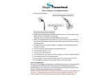
Fit 3 x AA batteries (supplied) into the wireless controller.
Depending on the type and version of your wireless controller, the software
revision number (eg. r04) may be briey displayed, the controller will then
display its default time of 10:00.
Place Wireless Controller in approximate nal position (no
more than 10 m (free air) from Digital Mixer Valve) and
test wireless signal by pressing the “ ” and adjusting the
temperature. If temperature display remains unchanged
and “out of range” symbol is displayed, units are unable to
communicate with each other.
If test fails, reposition unit(s) and repeat
test until satised shower will work
reliably.
Caution! Risk of product damage. Do
not run Pumped Valve (low pressure
version) without a water supply for
longer than 15 minutes during test.
Fixing Screw x 3
Mark the xing holes in the required positions.
Isolate electrical supply to
Digital Mixer Valve.

20
Drill and plug the xing holes.
Note! Installers may wish to use alternative cavity xings, when installing
onto a dry lined, stud partition, shower cubicle or laminated panel wall
structures. However, these methods of xing are beyond the scope of this
guide.
Secure the Digital Mixer Valve in position with the xing screws (supplied).
Caution! Risk of product damage. Make sure both hot and cold supply
pipesareushedthoroughlypriortoconnectiontotheDigitalMixer
Valve. Any product malfunction caused by pipework debris is not
covered under the guarantee.
Connect the hot and cold water supply pipes to the Digital Mixer Valve.
Install the Shower Fittings and Wireless Controller (see further instructions).
Wiring to
Fused Spur Box
Push-t connector to the
Shower Fittings
Outlet
Cold Inlet
Hot Inlet
Push-t Isolators tted
to both Inlets
/