Page is loading ...

Vaisala DRYCAP
®
Dewpoint Transmitter DMT242
USER'S GUIDE June 2008 | M010036EN-D
INTRODUCTION
DMT242 is a dewpoint transmitter for wide range of OEM applications. DMT242 measures dewpoint
with excellent long term stability which is maintained automatically with the patented auto-calibration
procedure. The Vaisala DRYCAP
®
polymer sensor technology used in DMT242 is also durable against
dew in case condenced water exists in the process during system malfunction. The product mechanics
have been designed for harsh environments requiring protection against dust, dirt and splashed water.
The disconnection and reconnection of the transmitter is easy with the connector where the output signal
and supply voltage wires are connected. The unit also has a serial line for rescaling the analog output.
PRESSURE SETTING PROCEDURE FOR PRESSURIZED PROCESSES
For achieving the most accurate measurements
in pressurized processes, set the process
pressure to DMT242 according to Figure 1 by
using the pressure switches (see Figure 3, item
8). As shipped from factory, the pressure
switch setting is 1 bar, as in switch number 4 in
the ON position.
MOUNTING
1. Insert the sealing washer (see Figure 1) on
the probe and set the probe through the
fitting of the process pipe. The probe has
G½" ISO 228/1 parallel thread.
2. Fasten the transmitter to the fitting of the
process pipe by tightening from the nut of
the probe (24 mm).
WIRING
1. Remove the cover.
2. Take out the connector.
3. Take out the screw terminal from the
connector by pushing it out, for example,
with the fixing screw.
4. Use a three-wire cable. Suitable 2 m or
10 m optional cable is available from
Vaisala (items: 221475 for 2 m cable and
221476 for 10 m cable). Connect the wires
to the connector terminals as follows:
2341
Switches Pressure (absolute)
2 … 4
0 … 2
12 … 14
4 … 6
8 … 10
10 … 12
14 … 16
6 … 8
18 … 20
16 … 18
(bar)
Figure 1 Pressure Setting Table
Figure 2 DMT242
Terminal nr 1 = V supply + (VAC line)
Terminal nr 2 = V supply - (VAC neutral)/signal -
Terminal nr 3 = Signal +
Leave the ground terminal free
+
-
THE SWITCH MARKED WITH
A BLACK SQUARE IS IN
THE
ON POSITION
1 = Cover
2 = Connector
3 = Flat gasket
4 = Counter connector
5 = Transmitter body
6 = Nut
7 = Sealing washer
8 = Probe
Wire colours in cables
221475 and 221476:
1 = brown
2 = blue
3 = black

Vaisala DRYCAP
®
Dewpoint Transmitter DMT242
USER'S GUIDE June 2008 | M010036EN-D
5. Insert the wired screw terminal back into the connector excatly in the position indicated in Figure 3.
Push the fixing screw through the connector. Fasten the cable clamp. Insert the wired connector into
the counter connector.
NOTE
The connection is incompatible if the positioning of the screw terminal is NOT as
indicated in Figure 3. Fasten the fixing screw.
6. Install the back cover allowing the cable to run through the hole in the cover. The transmitter is ready
for use.
NOTE
When the power is switched on, wait about 7 minutes before taking measurements.
Start-up self-diagnostics freeze the output during the first operation minutes.
Figure 3 Wiring and Installation of Connector
CALIBRATION AND MAINTENANCE
Replacing the sintered filter
If the sintered filter is dirty it can prolong the response time of the measurement. If the filter needs to be
changed unscrew the filter and replace the old filter with a new one.
Calibration
It is recommended to perform a calibration check every other year. A field check can be carried out by
using a calibrated reference probe and comparing the readings measured with the transmitter and the
reference probe. The Vaisala DRYCAP
®
Hand-Held Dewpoint Meter DM70 is ideal for confirming the
performance of the transmitter in the field. By using a connection cable the readings of DMT242 and
DM70 can be viewed simultaneously on the display of DM70. If there is need for adjustement contact
Vaisala Instruments Service Centers or local Vaisala representative.
SCREW TERMINAL MUST BE INSTALLED TO THE
CONNECTOR IN THE POSITION OF THE FIGURE
(TERMINALS 2 AND 3 AS UPPER EDGE)
1 = Connector
2 = Screw terminal of the connector
3 = Connector
4 = Cable clamp
5 = RS-232 serial port
6 = Terminals 2 and 3
7 = Three-wire cable
8 = Pressure setting switches
9 = Fixing screw

Vaisala DRYCAP
®
Dewpoint Transmitter DMT242
USER'S GUIDE June 2008 | M010036EN-D
SCALING THE ANALOG OUTPUT VIA THE SERIAL BUS
Serial communication settings
The analog output scaling can be done using the serial bus and computer with suitable terminal software.
Connect the DMT242 to a serial bus via the RS-232 interface by using the following settings: Baud rate:
2400, Parity: none, Data bits: 8, Stop bits: 1. The serial cable (DMT242RS) can be ordered from Vaisala.
Scaling of the dewpoint output
Scale the dewpoint parameter by giving the command ascl xx yy<ENTER> where xx = the low limit
(C or ºF) and yy = the high limit (C or ºF). The factory setting for serial measurement unit is
Centigrade (C). To change the unit for Fahrenheit (ºF) use command unit xx <ENTER> where xx = n
for non-metric (ºF) and xx = m for metric (C) units.
ACCESSORIES
Order Code Description
HM47280 Stainless steel sintered filter
DMT242RS RS-232 serial line cable for PC (with female D connector)
210662 1/2" NPT adapter
GUARANTEE
Vaisala issues a guarantee for the material and workmanship of this product under normal operating
conditions for one (1) year from the date of delivery. Exceptional operating conditions, damage due to
careless handling and misapplication will void the guarantee.

Vaisala DRYCAP
®
Dewpoint Transmitter DMT242
USER'S GUIDE June 2008 | M010036EN-D
TECHNICAL SPECIFICATIONS
Dewpoint Temperature
Measurement range -80 ... +60 °C (-112 ... +140 °F)
DMT242A -80 ... +20 °C (-112 ... +68 °F)
DMT242B -60 ... +60 °C (-76 ... +140 °F)
DMT242X free scaling
When the dewpoint is below 0 C, the transmitter outputs
frost point.
Dewpoint accuracy with
DRYCAP
®
180M ±2 ºC (±3.6 ºF)
(See figure below)
Response time 63 % [90 %] at 20 °C gas temperature at
flow rate > 1 l/min and 1 bar pressure:
-60 -20 °C T
d
(-76 -4 °F T
d
)
5 s [10 s]
-20 -60 °C T
d
(-4 -76 °F T
d
)
45 s [10 min]
DRYCAP
®
180S ±2 ºC (±3.6 ºF)
(See figure below)
Operating Environment
Temperature 0 ... +60 ºC (32 ... +140 ºF)
Higher temperature peaks Short term OK
Relative humidity 0 ... 100 %RH
Pressure 0 ... 20 bar
a
(0 ... 290 psi
a
)
Sample flow rate no effect
Output
Analog output 4 ... 20 mA
Resolution for analog output ±0.002 mA
Typical temperature dependence 0.0008 mA/ºC
Serial line for service use RS-232
General
Sensor DRYCAP
®
180M
Operation voltage 17 ... 35 VDC
20 ... 28 VAC
Power consumption 24 VDC max 220 mA
External load for current
output
max 500 Ω
Optional connection cable
with DMT242 connector
2 m or 10 m
Connector for supply voltage
and signal output
Max wire size 0.75 mm
2
Max wire diameter 6.5 mm/PG7
Service cable for serial line DMT242RS
Probe material stainless steel
(AISI 316L)
Sensor protection stainless steel sintered
filter (HM47280)
Mechanical connection G1/2" ISO228-1 thread
with bonded seal ring
(U-seal)
Electronics housing plastic (ABS/PC)
Housing classification IP 65 (NEMA 4)
Storage temperature range -40 ... +70 ºC
(-40 ... +158 ºF)
Complies with EMC standard EN61326-1:1997 +
Am1:1998 + Am2:2001; Industrial Environment.
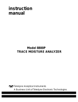
Figure 4 Dimensions in mm [inches]
*
M
010036
EN
*
/