Toro LX460 Lawn Tractor User manual

Category
Lawnmowers
Type
User manual
LX Lawn
Tractor
Service Manual
Consumer Products
iLX Lawn Tractor Service Manual
TABLE OF CONTENTS
1-1
1-1
2-1
2-2
2-3
2-4
2-5
2-6
3-1
3-7
3-14
3-17
3-19
3-20
3-21
3-24
3-27
3-28
3-29
3-30
3-31
3-32
3-33
3-39
3-45
3-53
3-62
3-64
3-67
3-69
3-71
3-74
3-77
3-79
SAFETY INFORMATION
General Information . . . . . . . . . . . . . . . . . . . . . . . . . . . . . . . . . .
Think Safety First . . . . . . . . . . . . . . . . . . . . . . . . . . . . . . . . . . .
SPECIFICATIONS
Torque Speci cations . . . . . . . . . . . . . . . . . . . . . . . . . . . . . . . . .
Standard Torque for Dry, Zinc Plated and Steel Fasteners (Inch Series) . . . . . . . . . . . . . .
Standard Torque for Dry, Zinc and Steel Fasteners (Metric Fasteners) . . . . . . . . . . . . . .
Other Torque Speci cations . . . . . . . . . . . . . . . . . . . . . . . . . . . . . . .
Equivalents and Conversions . . . . . . . . . . . . . . . . . . . . . . . . . . . . . .
Product Speci cations . . . . . . . . . . . . . . . . . . . . . . . . . . . . . . . . .
CHASSIS
Front Pivot Axle Replacement
Removal . . . . . . . . . . . . . . . . . . . . . . . . . . . . . . . . . . . . .
Installation . . . . . . . . . . . . . . . . . . . . . . . . . . . . . . . . . . . .
Axle Assembly Replacement
Removal . . . . . . . . . . . . . . . . . . . . . . . . . . . . . . . . . . . . .
Installation . . . . . . . . . . . . . . . . . . . . . . . . . . . . . . . . . . . .
Steering Wheel Replacement
Removal . . . . . . . . . . . . . . . . . . . . . . . . . . . . . . . . . . . . .
Installation . . . . . . . . . . . . . . . . . . . . . . . . . . . . . . . . . . . .
Steering Shaft Replacement
Removal . . . . . . . . . . . . . . . . . . . . . . . . . . . . . . . . . . . . .
Installation . . . . . . . . . . . . . . . . . . . . . . . . . . . . . . . . . . . .
Electric PTO Clutch Replacement
Removal . . . . . . . . . . . . . . . . . . . . . . . . . . . . . . . . . . . . .
Installation . . . . . . . . . . . . . . . . . . . . . . . . . . . . . . . . . . . .
Fuel Tank Replacement
Removal . . . . . . . . . . . . . . . . . . . . . . . . . . . . . . . . . . . . .
Installation . . . . . . . . . . . . . . . . . . . . . . . . . . . . . . . . . . . .
Hood Replacement
Removal . . . . . . . . . . . . . . . . . . . . . . . . . . . . . . . . . . . . .
Installation . . . . . . . . . . . . . . . . . . . . . . . . . . . . . . . . . . . .
Fender Replacement
Removal . . . . . . . . . . . . . . . . . . . . . . . . . . . . . . . . . . . . .
Installation . . . . . . . . . . . . . . . . . . . . . . . . . . . . . . . . . . . .
Tower Replacement
Removal . . . . . . . . . . . . . . . . . . . . . . . . . . . . . . . . . . . . .
Installation . . . . . . . . . . . . . . . . . . . . . . . . . . . . . . . . . . . .
Lower Transmission Drive Belt Replacement - Gear Drive Models
Removal . . . . . . . . . . . . . . . . . . . . . . . . . . . . . . . . . . . . .
Installation . . . . . . . . . . . . . . . . . . . . . . . . . . . . . . . . . . . .
Upper Transmission Drive Belt Replacement - Gear Drive Models
Removal . . . . . . . . . . . . . . . . . . . . . . . . . . . . . . . . . . . . .
Installation . . . . . . . . . . . . . . . . . . . . . . . . . . . . . . . . . . . .
Transmission Drive Belt (Hydro) Replacement
Removal . . . . . . . . . . . . . . . . . . . . . . . . . . . . . . . . . . . . .
Installation . . . . . . . . . . . . . . . . . . . . . . . . . . . . . . . . . . . .
Variable Speed Pulley Replacement
Removal . . . . . . . . . . . . . . . . . . . . . . . . . . . . . . . . . . . . .
Installation . . . . . . . . . . . . . . . . . . . . . . . . . . . . . . . . . . . .
ii LX Lawn Tractor Service Manual
TABLE OF CONTENTS
3-81
3-82
3-82
3-83
3-84
3-85
3-86
3-87
3-91
3-93
3-96
4-1
4-7
5-1
5-4
5-9
5-11
5-14
6-1
6-7
7-1
7-3
7-6
7-8
7-11
7-13
7-14
7-16
7-19
7-20
7-21
7-23
CHASSIS cont.
Variable Speed Pulley Service
Disassembly . . . . . . . . . . . . . . . . . . . . . . . . . . . . . . . . . . .
Assembly . . . . . . . . . . . . . . . . . . . . . . . . . . . . . . . . . . . .
Purging the System - Hydrostatic Models . . . . . . . . . . . . . . . . . . . . . . . . . .
Fluid Change - Hydrostatic Models . . . . . . . . . . . . . . . . . . . . . . . . . . . .
Neutral Adjustment - Hydrostatic Models . . . . . . . . . . . . . . . . . . . . . . . . . .
Front Wheel Toe-in Measurement . . . . . . . . . . . . . . . . . . . . . . . . . . . . .
Front Wheel Toe-in Adjustment . . . . . . . . . . . . . . . . . . . . . . . . . . . . . .
Autodrive Pedal Adjustment - Hydrostatic Models . . . . . . . . . . . . . . . . . . . . . . .
Brake Adjustment - Hydrostatic Models . . . . . . . . . . . . . . . . . . . . . . . . . . .
Throttle/Choke Cable Replacement
Removal . . . . . . . . . . . . . . . . . . . . . . . . . . . . . . . . . . . . .
Installation . . . . . . . . . . . . . . . . . . . . . . . . . . . . . . . . . . . .
ENGINE
Engine Replacement
Removal . . . . . . . . . . . . . . . . . . . . . . . . . . . . . . . . . . . . .
Installation . . . . . . . . . . . . . . . . . . . . . . . . . . . . . . . . . . . .
GEAR DRIVE SYSTEM
CVT Transmission Replacement
Removal . . . . . . . . . . . . . . . . . . . . . . . . . . . . . . . . . . . . .
Installation . . . . . . . . . . . . . . . . . . . . . . . . . . . . . . . . . . . .
Brake Puck Replacement
Removal . . . . . . . . . . . . . . . . . . . . . . . . . . . . . . . . . . . . .
Installation . . . . . . . . . . . . . . . . . . . . . . . . . . . . . . . . . . . .
Brake Adjustment . . . . . . . . . . . . . . . . . . . . . . . . . . . . . . . . . . .
HYDROSTATIC DRIVE SYSTEM
Hydro Transmission Replacement
Removal . . . . . . . . . . . . . . . . . . . . . . . . . . . . . . . . . . . . .
Installation . . . . . . . . . . . . . . . . . . . . . . . . . . . . . . . . . . . .
MOWER DECK
42” Mower Deck - Brake Idler Assembly Replacement
Removal . . . . . . . . . . . . . . . . . . . . . . . . . . . . . . . . . . . . .
Installation . . . . . . . . . . . . . . . . . . . . . . . . . . . . . . . . . . . .
42” Mower Deck - Idler Assembly Replacement
Removal . . . . . . . . . . . . . . . . . . . . . . . . . . . . . . . . . . . . .
Installation . . . . . . . . . . . . . . . . . . . . . . . . . . . . . . . . . . . .
42” Mower Belt Replacement
Removal . . . . . . . . . . . . . . . . . . . . . . . . . . . . . . . . . . . . .
Installation . . . . . . . . . . . . . . . . . . . . . . . . . . . . . . . . . . . .
46” Mower Deck - RH Idler Bracket Assembly
Removal . . . . . . . . . . . . . . . . . . . . . . . . . . . . . . . . . . . . .
Installation . . . . . . . . . . . . . . . . . . . . . . . . . . . . . . . . . . . .
46” Mower Deck - Brake Assembly
Removal . . . . . . . . . . . . . . . . . . . . . . . . . . . . . . . . . . . . .
Installation . . . . . . . . . . . . . . . . . . . . . . . . . . . . . . . . . . . .
46” Mower Deck - LH Idler Assembly
Removal . . . . . . . . . . . . . . . . . . . . . . . . . . . . . . . . . . . . .
Installation . . . . . . . . . . . . . . . . . . . . . . . . . . . . . . . . . . . .
iiiLX Lawn Tractor Service Manual
TABLE OF CONTENTS
7-25
7-26
7-27
7-30
7-34
7-35
7-36
7-38
7-39
7-41
7-43
7-45
7-47
7-51
7-56
7-60
7-64
7-67
7-69
7-72
7-74
7-76
8-1
MOWER DECK cont.
46” Mower Deck - Lower Idler Bracket
Removal . . . . . . . . . . . . . . . . . . . . . . . . . . . . . . . . . . . . .
Installation . . . . . . . . . . . . . . . . . . . . . . . . . . . . . . . . . . . .
46” Mower Deck - Lower Mower Deck Belt Replacement
Removal . . . . . . . . . . . . . . . . . . . . . . . . . . . . . . . . . . . . .
Installation . . . . . . . . . . . . . . . . . . . . . . . . . . . . . . . . . . . .
46” Mower Deck - Upper Mower Deck Belt Replacement
Removal . . . . . . . . . . . . . . . . . . . . . . . . . . . . . . . . . . . . .
Installation . . . . . . . . . . . . . . . . . . . . . . . . . . . . . . . . . . . .
50” Mower Deck - Belt Replacement
Removal . . . . . . . . . . . . . . . . . . . . . . . . . . . . . . . . . . . . .
Installation . . . . . . . . . . . . . . . . . . . . . . . . . . . . . . . . . . . .
50” Mower Deck - Idler Replacement
Removal . . . . . . . . . . . . . . . . . . . . . . . . . . . . . . . . . . . . .
Installation . . . . . . . . . . . . . . . . . . . . . . . . . . . . . . . . . . . .
42” Mower Deck - Spindle Replacement
Removal . . . . . . . . . . . . . . . . . . . . . . . . . . . . . . . . . . . . .
Installation . . . . . . . . . . . . . . . . . . . . . . . . . . . . . . . . . . . .
42” Mower Deck - Spindle Service . . . . . . . . . . . . . . . . . . . . . . . . . . . .
46” Mower Deck - Double Pulley Spindle Service . . . . . . . . . . . . . . . . . . . . . .
46” Mower Deck - Single Pulley Spindle Service . . . . . . . . . . . . . . . . . . . . . . .
50” Mower Deck - Spindle Service . . . . . . . . . . . . . . . . . . . . . . . . . . . .
42” Mower Deck Removal . . . . . . . . . . . . . . . . . . . . . . . . . . . . . . . .
42” Mower Deck Installation . . . . . . . . . . . . . . . . . . . . . . . . . . . . . . .
46” Mower Deck Removal . . . . . . . . . . . . . . . . . . . . . . . . . . . . . . . .
46” Mower Deck Installation . . . . . . . . . . . . . . . . . . . . . . . . . . . . . . .
50” Mower Deck Removal . . . . . . . . . . . . . . . . . . . . . . . . . . . . . . . .
50” Mower Deck Installation . . . . . . . . . . . . . . . . . . . . . . . . . . . . . . .
ELECTRICAL
Electrical System . . . . . . . . . . . . . . . . . . . . . . . . . . . . . . . . . . .
iv LX Lawn Tractor Service Manual
TABLE OF CONTENTS
THIS PAGE INTENTIONALLY LEFT BLANK.
1-iLX Lawn Tractor Service Manual
1
SAFETY INFORMATION
General Information
This symbol means WARNING or
PERSONAL SAFETY INSTRUCTION
- read the instruction because it has to
do with your safety. Failure to comply
with the instruction may result in
personal injury or even death.
This manual is intended as a service and repair
manual only. The safety instructions provided herein
are for troubleshooting, service, and repair of the
LX Series Riding Lawn Tractor.
The riding mower and attachment operator's manual
contain safety information and operating tips for safe
operating practices. Operator's manuals are available
through your Toro parts source or:
The Toro Company
Publications Department
8111 Lyndale Avenue South
Bloomington, MN 55420
Think Safety First
Avoid unexpected starting of engine...
Always turn off the engine and disconnect the spark
plug wire(s) before cleaning, adjusting, or repair.
Avoid lacerations and amputations...
Stay clear of all moving parts whenever the engine is
running. Treat all normally moving parts as if they were
moving whenever the engine is running or has the
potential to start.
Avoid burns...
Do not touch the engine, muffler, or other components
which may increase in temperature during operation,
while the unit is running or shortly after it has been
running.
Avoid fires and explosions...
Avoid spilling fuel and never smoke while working with
any type of fuel or lubricant. Wipe up any spilled fuel or
oil immediately. Never remove the fuel cap or add fuel
when the engine is running. Always use approved,
labeled containers for storing or transporting fuel and
lubricants.
Avoid asphyxiation...
Never operate an engine in a confined area without
proper ventilation.
Avoid injury from batteries...
Battery acid is poisonous and can cause burns. Avoid
contact with skin, eyes, and clothing. Battery gases
can explode. Keep cigarettes, sparks, and flames away
from the battery.
Avoid injury due to inferior parts...
Use only original equipment parts to ensure that
important safety criteria are met.
Avoid injury to bystanders...
Always clear the area of bystanders before starting or
testing powered equipment.
Avoid injury due to projectiles...
Always clear the area of sticks, rocks, or any other
debris that could be picked up and thrown by the
powered equipment.
Avoid modifications...
Never alter or modify any part unless it is a factory
approved procedure.
Avoid unsafe operation...
Always test the safety interlock system after making
adjustments or repairs on the machine. Refer to the
Electrical section in this manual for more information.
1-ii LX Lawn Tractor Service Manual
1
THIS PAGE INTENTIONALLY LEFT BLANK.
SAFETY INFORMATION
SPECIFICATIONS
2-1LX Lawn Tractor Service Manual
2
Torque Specifications
Recommended fastener torque values are listed in the
following tables. For critical applications, as
determined by Toro, either the recommended torque or
a torque that is unique to the application is clearly
identified and specified in the service manual.
These torque specifications for the installation and
tightening of fasteners shall apply to all fasteners which
do not have a specific requirement identified in the
service manual. The following factors shall be
considered when applying torque: cleanliness of the
fastener, use of a thread sealant (Loctite), degree of
lubrication on the fastener, presence of a prevailing
torque feature, hardness of the surface underneath of
the fastener’s head, or similar condition which affects
the installation.
As noted in the following tables, torque values should
be reduced by 25% for lubricated fasteners to
achieve the similar stress as a dry fastener. Torque
values may also have to be reduced when the fastener
is threaded into aluminum or brass. The specific
torque value should be determined based on the
aluminum or brass material strength, fastener size,
length of thread engagement, etc.
The standard method of verifying torque shall be
performed by marking a line on the fastener (head or
nut) and mating part, then back off fastener 1/4 of a
turn. Measure the torque required to tighten the
fastener until the lines match up.
Fastener Identification
Figure 1
Figure 2
Inch Series Bolts and Screws
(A) Grade 1
(B) Grade 5
(C) Grade 8
Metric Bolts and Screws
(A) Class 8.8 (B) Class 10.9
SPECIFICATIONS
2-2 LX Lawn Tractor Service Manual
2
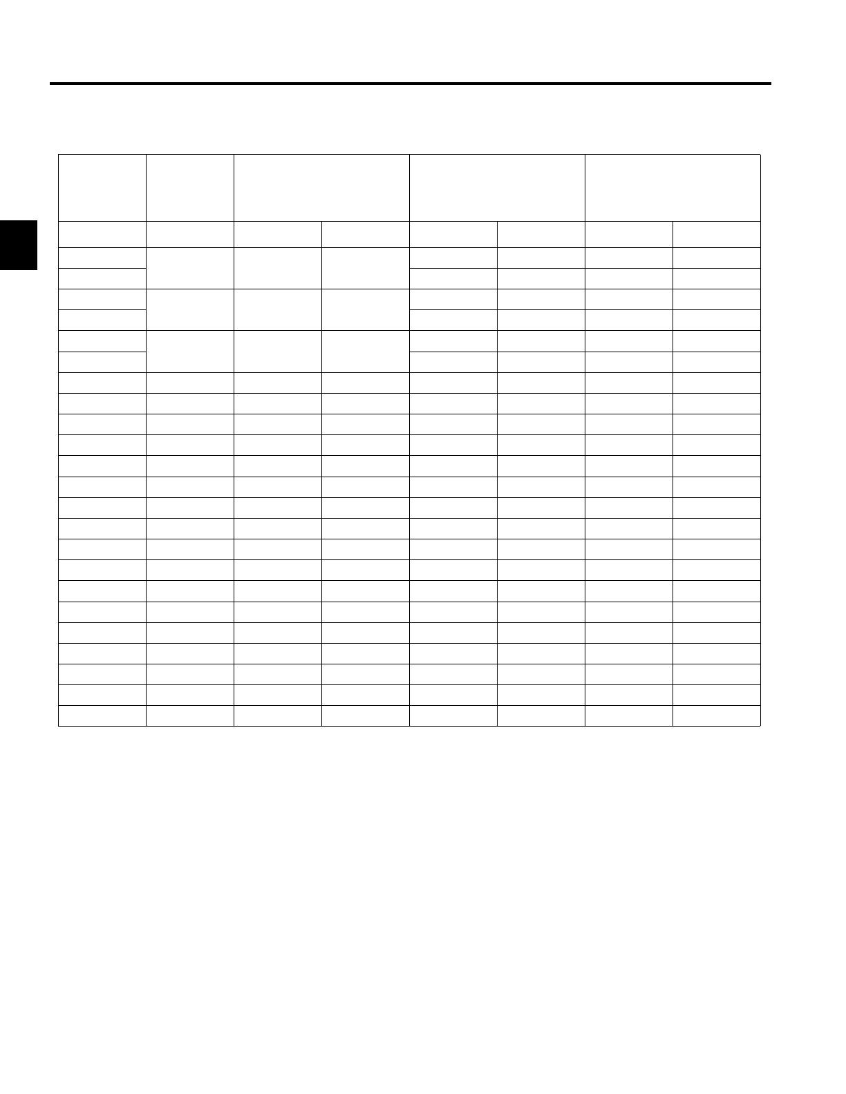
Standard Torque for Dry, Zinc Plated, and Steel Fasteners (Inch Series)
Note: Reduce torque values listed in the table above
by 25% for lubricated fasteners. Lubricated fasteners
are defined as threads coated with a lubricant such as
oil, graphite, or thread sealant such as Loctite.
Note: Torque values may have to be reduced when
installing fasteners into threaded aluminum or brass.
The specific torque value should be determined based
on the fastener size, the aluminum or base material
strength, length of thread engagement, etc.
Note: The nominal torque values listed above for
Grade 5 and 8 fasteners are based on 75% of the
minimum proof load specified in SAE J429. The
tolerance is approximately
± 10% of the nominal torque
value. Thin height nuts include jam nuts.
Thread Size
Grade 1, 5, &
8 with Thin
Height Nuts
SAE Grade 1 Bolts, Screws,
Studs, & Sems with Regular
Height Nuts (SAE J995 Grade
2 or Stronger Nuts)
SAE Grade 5 Bolts, Screws,
Studs, & Sems with Regular
Height Nuts (SAE J995 Grade
2 or Stronger Nuts)
SAE Grade 8 Bolts, Screws,
Studs, & Sems with Regular
Height Nuts (SAE J995 Grade
2 or Stronger Nuts)
In-lb In-lb N-cm In-lb N-cm In-lb N-cm
# 6 - 32 UNC
10 ± 2 13 ± 2 147 ± 23
15 ± 2 170 ± 20 23 ± 2 260 ± 20
# 6 - 40 UNF 17 ± 2 190 ± 20 25 ± 2 280 ± 20
# 8 - 32 UNC
13 ± 2 25 ± 5 282 ± 30
29 ± 3 330 ± 30 41 ± 4 460 ± 45
# 8 - 36 UNF 31 ± 3 350 ± 30 43 ± 4 31 ± 3
# 10 - 24 UNC
18 ± 2 30 ± 5 339 ± 56
42 ± 4 475 ± 45 60 ± 6 674 ± 70
#10 - 32 UNF 48 ± 4 540 ± 45 68 ± 6 765 ± 70
1/4 - 20 UNC 48 ± 7 53 ± 7 599 ± 79 100 ± 10 1125 ± 100 140 ± 15 1580 ± 170
1/4 - 28 UNF 53 ± 7 65 ± 10 734 ± 113 115 ± 10 1300 ± 100 160 ± 15 1800 ± 170
5/16 - 18 UNC 115 ± 15 105 ± 17 1186 ± 169 200 ± 25 2250 ± 280 300 ± 30 3390 ± 340
5/16 - 24 UNF 138 ± 17 128 ± 17 1446 ± 192 225 ± 25 2540 ± 280 325 ± 30 3670 ± 340
ft-lb ft-lb N-m ft-lb N-m ft-lb N-m
3/8 - 16 UNC 16 ± 2 16 ± 2 22 ± 3 30 ± 3 41 ± 4 43 ± 4 58 ± 5
3/8 - 24 UNF 17 ± 2 18 ± 2 24 ± 3 35 ± 3 47 ± 4 50 ± 4 68 ± 5
7/16 - 14 UNC 27 ± 3 27 ± 3 37 ± 4 50 ± 5 68 ± 7 70 ± 7 68 ± 9
7/16 - 20 UNF 29 ± 3 29 ± 3 39 ± 4 55 ± 5 75 ± 7 77 ± 7 104 ± 9
1/2 - 13 UNC 30 ± 3 48 ± 7 65 ± 9 75 ± 8 102 ± 11 105 ± 10 142 ± 14
1/2 - 20 UNF 32 ± 3 53 ± 7 72 ± 9 85 ± 8 115 ± 11 120 ± 10 163 ± 14
5/8 - 11 UNC 65 ± 10 88 ± 12 119 ± 16 150 ± 15 203 ± 20 210 ± 20 285 ± 27
5/8 - 18 UNF 75 ± 10 95 ± 15 129 ± 20 170 ± 15 230 ± 20 240 ± 20 325 ± 27
3/4 - 10 UNC 93 ± 12 140 ± 20 190 ± 27 265 ± 25 359 ± 34 374 ± 35 508 ± 47
3/4 - 16 UNF 115 ± 15 165 ± 25 224 ± 34 300 ± 25 407 ± 34 420 ± 35 569 ± 47
7/8 - 9 UNC 140 ± 20 225 ± 25 305 ± 34 430 ± 45 583 ± 61 600 ± 60 813 ± 81
7/8 - 14 UNF 155 ± 25 260 ± 30 353 ± 41 475 ± 45 644 ± 61 660 ± 60 895 ± 81
SPECIFICATIONS
2-3LX Lawn Tractor Service Manual
2
Standard Torque for Dry, Zinc, and Steel Fasteners (Metric Fasteners)
Note: Reduce torque values listed in the table above
by 25% for lubricated fasteners. Lubricated fasteners
are defined as threads coated with a lubricant such as
oil, graphite, or thread sealant such as Loctite.
Note: Torque values may have to be reduced when
installing fasteners into threaded aluminum or brass.
The specific torque value should be determined based
on the fastener size, the aluminum or base material
strength, length of thread engagement, etc.
Note: The nominal torque values listed above are
based on 75% of the minimum proof load specified in
SAE J1199. The tolerance is approximately
± 10% of
the nominal torque value. Thin height nuts include jam nuts.
Thread Size
Class 8.8 Bolts, Screws, and Studs with
Regular Height Nuts
(Class 8 or Strong Nuts)
Class 10.9 Bolts, Screws, and Studs with
Regular Height Nuts (
Class 10 or Strong Nuts)
M5 X 0.8 57 ± 5 in-lb 640 ± 60 N-cm 78 ± 7 in-lb 885 ± 80 N-cm
M6 X 1.0 96 ± 9 in-lb 1018 ± 100 N-cm 133 ± 13 in-lb 1500 ± 150 N-cm
M8 X 1.25 19 ± 2 ft-lb 26 ± 3 N-m 27 ± 2 ft-lb 36 ± 3 N-m
M10 X 1.5 38 ± 4 ft-lb 52 ± 5 N-m 53 ± 5 ft-lb 72 ± 7 N-m
M12 X 1.75 66 ± 7 ft-lb 90 ± 10 N-m 92 ± 9 ft-lb 125 ± 12 N-m
M16 X 2.0 166 ± 15 ft-lb 225 ± 20 N-m 229 ± 22 ft-lb 310 ± 30 N-m
M20 X 2.5 325 ± 33 ft-lb 440 ± 45 N-m 450 ± 37 ft-lb 610 ± 50 N-m
SPECIFICATIONS
2-4 LX Lawn Tractor Service Manual
2
Other Torque Specifications
SAE Grade 8 Steel Set Screws
Thread Cutting Screws
(Zinc Plated Steel)
Conversion Factors
in-lb X 11.2985 - N-cm
ft-lb X 1.3558 = N-m
Wheel Bolts and Lug Nuts
** For steel wheels and non-lubricated fasteners.
Thread Cutting Screws
(Zinc Plated Steel)
* Hole size, material strength, material thickness and
finish must be considered when determining specific
torque values. All torque values are based on non-
lubricated fasteners.
N-cm X - 0.08851 = in-lb
N-cm X 0.73776 - ft-lb
Thread Size
Recommended Torque
Square Head Hex Socket
1/4 - 20 UNC 140 ± 20 in-lb 73 ± 12 in-lb
5/16 - 18 UNC 215 ± 35 in-lb 145 ± 20 in-lb
3/8 - 16 UNC 35 ± 10 ft-lb 18 ± 3 ft-lb
1/2 - 13 UNC 75 ± 15 ft-lb 50 ± 10 ft-lb
Type 1, Type 23, or Type F
Thread Size Baseline Torque*
No. 6 - 32 UNC 20 ± 5 in-lb
No. 8 - 32 UNC 30 ± 5 in-lb
No.10 - 24 UNC 38 ± 7 in-lb
1/4 - 20 UNC 85 ± 15 in-lb
5/16 - 18 UNC 110 ± 20 in-lb
3/8 - 16 UNC 200 ± 100 in-lb
Thread Size Recommended Torque**
7/16 - 20 UNF
Grade 5
65 ± 10 ft-lb 88 ± 14 N-m
1/2 - 20 UNF
Grade 5
80 ± 10 ft-lb 108 ± 14 N-m
M12 X 1.25
Class 8.8
80 ± 10 ft-lb 108 ± 14 N-m
M12 X 1.5
Class 8.8
80 ± 10 ft-lb 108 ± 14 N-m
Thread
Size
Threads per Inch
Baseline Torque*
Type A Type B
No. 6 18 20 20 ± 5 in-lb
No. 8 15 18 30 ± 5 in-lb
No. 10 12 16 38 ± 7 in-lb
No. 12 11 14 85 ± 15 in-lb
SPECIFICATIONS
2-5LX Lawn Tractor Service Manual
2
Equivalents and Conversions
SPECIFICATIONS
2-6 LX Lawn Tractor Service Manual
2
Name LX420 LX425 LX460 LX465 LX500
Engine 18 HP
Single Cylinder
Kohler Courage
20 HP
Single Cylinder
Kohler Courage
20 HP
Single Cylinder
Kohler Courage
20 HP
Single Cylinder
Kohler Courage
22 HP
Twin Cylinder
Kohler Courage
RPM Setting -
High
3450 + 75 3450 + 75 3450 + 75 3450 + 75 3300 + 75
RPM Setting –
Low
1700 + 150 1700 + 150 1700 + 150 1700 + 150 1750 + 150
Construction
Fuel Capacity
Wheel Base 46” (116.8cm) 46” (116.8cm) 46” (116.8cm) 46” (116.8cm) 46” (116.8cm)
Overall Length 68” (172.7cm) 68” (172.7cm) 68” (172.7cm) 68” (172.7cm) 68” (172.7cm)
Overall Width 42” (114.3cm) 42” (114.3cm) 48” (127.9cm) 49” (124.4cm) 54” (137.2cm)
Overall Height 43” (109.2cm) 43” (109.2cm) 43” (109.2cm) 43” (109.2cm) 43” (109.2cm)
Weight
(approximate)
498 lbs.
(225.9kg)
498 lbs.
(225.9kg)
501 lbs.
(227.25kg)
498 lbs.
(225.9kg)
525 lbs.
(238kg)
Traction System CVT* Transaxle CVT* Transaxle CVT* Transaxle Hydro-Gear
LT-0510
CVT* Transaxle
Ground Speed –
Forward
0 – 5.5 mph 0 – 5.5 mph 0 – 5.5 mph 0 – 6.4 mph 0 – 5.5 mph
Ground Speed –
Reverse
0 – 2.3 mph 0 – 2.3 mph 0 – 2.3 mph 0 – 2.5 mph 0 – 2.3 mph
Front Tires
Rear Tires 20 x 8 20 x 8 20 x 8 20 x 8 20 x 10
Tire Pressure
(Front/Rear)
Turning Radius
Electrical
System
Mower Deck
42”, Two Blade,
13 Gauge Steel
42”, Two Blade,
13 Gauge Steel
46”, Three Blade,
12 Gauge Steel
46”, Three Blade,
12 Gauge Steel
50”, Three Blade,
12 Gauge Steel
CVT = Constant Velocity Transaxle
Voltage: 12-volt Negative
Ground Battery: 190 CCA
Alternator: 15 Amp Regulated
Fuse: 20 Amp
12 Gauge Steel Frame
15 x 6
3.0 Gallon (11.4 Liters)
14psi / 10psi
18” (46cm)
Product Speci cations
CHASSIS
3-1LX Lawn Tractor Service Manual
3
1. Disconnect the negative and then the positive
battery cable.
2. Remove the mower deck: 42” deck on page 7-64;
46” deck on page 7-69; 50” deck on page 7-74.
3. Remove the deck rod from the deck hanger bracket
(Fig. 001).
Front Pivot Axle Replacement
Removal
Fig 001 PICT-7399a
4. Raise the hood (Fig. 002).
Fig 002 PICT-7063
Fig 004 PICT-7066
6. Remove the hood from the frame (Fig. 004).
Fig 003 PICT-7064
5. Unplug the headlights from the wire harness (Fig.
003).
CHASSIS
3-2 LX Lawn Tractor Service Manual
3
Fig 006 PICT-7401
Fig 008 PICT-7403
9. Remove and discard the cotter pins from the two
axles (Fig. 006).
11. Remove the wheel and tire assembly from the two
axle assemblies (Fig. 008).
Fig 007 PICT-7402
Fig 005 PICT-7400
10. Remove the washer from the two axles (Fig. 007).7. Elevate and secure the front end of the machine so
the front axle can be accessed.
8. Remove the hub caps from the two front tires (Fig.
005).
CHASSIS
3-3LX Lawn Tractor Service Manual
3
Fig 010 PICT-7413
Fig 012 PICT-7421
Bushing stays on axle (Fig. 010):
13. Remove the nut securing the ball joint to the axle
assemblies (Fig. 012).
Fig 011 PICT-7415a
Fig 009 PICT-7410a
12. Remove the bushing from each of the axle assem-
blies if it stayed in place at tire assembly removal
(Fig. 011).
Note: There are inner and outer bushings included
with the rim assembly. When the wheel is
removed, the inner bushing may come off
with the wheel or stay on the axle.
Bushing stays in rim of tire (Fig. 009):
CHASSIS
3-4 LX Lawn Tractor Service Manual
3
Fig 014 PICT-7424
Fig 016 PICT-7431a
15. Remove the cap from the axle assembly (Fig. 014). 17. Remove the axle assembly from the front pivot axle
(Fig. 016).
18. Repeat steps 13-17 to remove the second axle.
Fig 015 PICT-7425
Fig 013 PICT-7423
16. Remove the push nut from the axle assembly (Fig.
015).
14. Remove the ball joint from the axle assembly (Fig.
013).
CHASSIS
3-5LX Lawn Tractor Service Manual
3
Fig 018 PICT-7462a
Fig 020 PICT-7442
20. Cut the electrical tape securing the wire harness to
the plastic harness guide (Fig. 018).
22. Remove the nuts from the 2 bolts securing the pivot
axle and deck hanger bracket to the frame (Fig.
020).
Fig 019 PICT-7439a
Fig 017 PICT-7434
21. Support the front pivot axle (Fig. 019).19. Cut the cable tie securing the wire harness to the
right hand hood pivot bracket (Fig. 017).
CHASSIS
3-6 LX Lawn Tractor Service Manual
3
Fig 022 PICT-7444
Fig 024 PICT-7449
24. Remove one of the bolts securing the deck hanger
plate and pivot axle to the frame (Fig. 022).
26. Remove the muf er, heat shield and bracket assem-
bly (Fig. 024).
Fig 023 PICT-7447
Fig 021 PICT-7436
25. Remove the second bolt and deck hanger plate from
the pivot axle (Fig. 023).
23. Remove the 4 bolts (2 on the right, 2 on the left)
securing the left and right pivot supports to the frame
(Fig. 021).
  • Page 1 1
  • Page 2 2
  • Page 3 3
  • Page 4 4
  • Page 5 5
  • Page 6 6
  • Page 7 7
  • Page 8 8
  • Page 9 9
  • Page 10 10
  • Page 11 11
  • Page 12 12
  • Page 13 13
  • Page 14 14
  • Page 15 15
  • Page 16 16
  • Page 17 17
  • Page 18 18
  • Page 19 19
  • Page 20 20
  • Page 21 21
  • Page 22 22
  • Page 23 23
  • Page 24 24
  • Page 25 25
  • Page 26 26
  • Page 27 27
  • Page 28 28
  • Page 29 29
  • Page 30 30
  • Page 31 31
  • Page 32 32
  • Page 33 33
  • Page 34 34
  • Page 35 35
  • Page 36 36
  • Page 37 37
  • Page 38 38
  • Page 39 39
  • Page 40 40
  • Page 41 41
  • Page 42 42
  • Page 43 43
  • Page 44 44
  • Page 45 45
  • Page 46 46
  • Page 47 47
  • Page 48 48
  • Page 49 49
  • Page 50 50
  • Page 51 51
  • Page 52 52
  • Page 53 53
  • Page 54 54
  • Page 55 55
  • Page 56 56
  • Page 57 57
  • Page 58 58
  • Page 59 59
  • Page 60 60
  • Page 61 61
  • Page 62 62
  • Page 63 63
  • Page 64 64
  • Page 65 65
  • Page 66 66
  • Page 67 67
  • Page 68 68
  • Page 69 69
  • Page 70 70
  • Page 71 71
  • Page 72 72
  • Page 73 73
  • Page 74 74
  • Page 75 75
  • Page 76 76
  • Page 77 77
  • Page 78 78
  • Page 79 79
  • Page 80 80
  • Page 81 81
  • Page 82 82
  • Page 83 83
  • Page 84 84
  • Page 85 85
  • Page 86 86
  • Page 87 87
  • Page 88 88
  • Page 89 89
  • Page 90 90
  • Page 91 91
  • Page 92 92
  • Page 93 93
  • Page 94 94
  • Page 95 95
  • Page 96 96
  • Page 97 97
  • Page 98 98
  • Page 99 99
  • Page 100 100
  • Page 101 101
  • Page 102 102
  • Page 103 103
  • Page 104 104
  • Page 105 105
  • Page 106 106
  • Page 107 107
  • Page 108 108
  • Page 109 109
  • Page 110 110
  • Page 111 111
  • Page 112 112
  • Page 113 113
  • Page 114 114
  • Page 115 115
  • Page 116 116
  • Page 117 117
  • Page 118 118
  • Page 119 119
  • Page 120 120
  • Page 121 121
  • Page 122 122
  • Page 123 123
  • Page 124 124
  • Page 125 125
  • Page 126 126
  • Page 127 127
  • Page 128 128
  • Page 129 129
  • Page 130 130
  • Page 131 131
  • Page 132 132
  • Page 133 133
  • Page 134 134
  • Page 135 135
  • Page 136 136
  • Page 137 137
  • Page 138 138
  • Page 139 139
  • Page 140 140
  • Page 141 141
  • Page 142 142
  • Page 143 143
  • Page 144 144
  • Page 145 145
  • Page 146 146
  • Page 147 147
  • Page 148 148
  • Page 149 149
  • Page 150 150
  • Page 151 151
  • Page 152 152
  • Page 153 153
  • Page 154 154
  • Page 155 155
  • Page 156 156
  • Page 157 157
  • Page 158 158
  • Page 159 159
  • Page 160 160
  • Page 161 161
  • Page 162 162
  • Page 163 163
  • Page 164 164
  • Page 165 165
  • Page 166 166
  • Page 167 167
  • Page 168 168
  • Page 169 169
  • Page 170 170
  • Page 171 171
  • Page 172 172
  • Page 173 173
  • Page 174 174
  • Page 175 175
  • Page 176 176
  • Page 177 177
  • Page 178 178
  • Page 179 179
  • Page 180 180
  • Page 181 181
  • Page 182 182
  • Page 183 183
  • Page 184 184
  • Page 185 185
  • Page 186 186
  • Page 187 187
  • Page 188 188
  • Page 189 189
  • Page 190 190
  • Page 191 191
  • Page 192 192
  • Page 193 193
  • Page 194 194
  • Page 195 195
  • Page 196 196
  • Page 197 197
  • Page 198 198
  • Page 199 199
  • Page 200 200
  • Page 201 201
  • Page 202 202
  • Page 203 203
  • Page 204 204
  • Page 205 205
  • Page 206 206
  • Page 207 207
  • Page 208 208
  • Page 209 209
  • Page 210 210
  • Page 211 211
  • Page 212 212
  • Page 213 213
  • Page 214 214
  • Page 215 215
  • Page 216 216
  • Page 217 217
  • Page 218 218
  • Page 219 219
  • Page 220 220
  • Page 221 221
  • Page 222 222
  • Page 223 223
  • Page 224 224
  • Page 225 225
  • Page 226 226
  • Page 227 227
  • Page 228 228
  • Page 229 229
  • Page 230 230
  • Page 231 231
  • Page 232 232
  • Page 233 233
  • Page 234 234
  • Page 235 235
  • Page 236 236

Toro LX460 Lawn Tractor User manual

Category
Lawnmowers
Type
User manual

Ask a question and I''ll find the answer in the document

Finding information in a document is now easier with AI