
1
IP2046/IM
Nov 2006
Mobrey
MSP400RH Series
Level Transmitter
Instruction & maintenance leaflet
IP2046IM, Rev. AA
November 2006
www.mobrey.com
MSP400RH

2
IP2046/IM
Nov 2006
CONTENTS
Page
1. Introduction 3
2. The MSP400RH ultrasonic level transmitter 3
2.1 Type numbering system 3
2.2 Pressure Equipment Directive 4
2.3 Specifications 4
3. Installation 6
3.1 Location of the MSP400RH transmitter 6
3.1.1 General considerations 6
3.1.2 Liquid surface conditions 7
3.1.3 In-tank / well effects 8
3.1.4 Open Channel Flow installations 8
3.2 Mounting the transmitter above the liquid surface 10
3.3 Wiring 11
3.4 Additional components in the 2 wire loop 12
4. Commissioning / Programming 13
4.1 Display & push buttons 13
4.2 Power up 14
4.3 Programming - important notes 14
4.4 Setting up for the chosen application 15
4.5 Diagnostic data 27
4.6 Loop Test 28
4.7 Engineering Set-up menu 29
5. Maintenance 35
Appendices
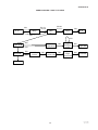
Appendix A1 Main Menu - Programming 36
Appendix A2 Diagnostic Menu 38
Appendix A3 Commissioning / Loop test menu 39
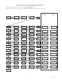
Appendix A4 Engineering menu 40
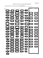
Appendix B Default menu listing 41
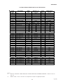
Appendix C Listing of non-linear profiles in the MSP400 43
Appendix D Hart Communications with the MSP400 44
Footnote :-
In this manual the following terms are used which refer to trademarks from other manufacturers:
HART: is the protocol adopted for the MSP400 SMART Communications.
HART is a registered trademark of the HART Communications Foundation and is a mnemonic For
Highway Addressable Remote Transducer.
The MSP400 transmitter is a measuring instrument
and should be handled with due
care and attention at all times

3
IP2046/IM
Nov 2006
1.0 Introduction
The MSP400 ultrasonic level transmitter is designed to be mounted above a liquid and will measure the
distance to the liquid surface.
When programmed with details of the vessel, sump or open channel, the MSP400 will compute level,
contents or flow and give a 4-20mA signal proportional to the chosen variable. 2 relays are provided for
control functions. Programming is achieved using integral push buttons or by remote communication
using HART protocol.
MSP400 is a two wire 24V dc loop powered transmitter and may be connected to any suitable dc power
source using 2 core shielded cable. The Mobrey MCU900 range of Control Units is designed to
be used with the MSP400 transmitter in this way.
The MSP400 transmitter must not be mounted in a hazardous area, even if supplied from a protected
power supply.
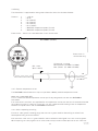
2.0 The MSP400RH ultrasonic level transmitter.
The transmitter operates over a range of 0.45m to 11m. When powered up the transmitter will give a
4-20mA signal on the two wire power cable over the factory default range :
4mA at 11m; 20mA at 0.45m. This range may be adjusted during commissioning. See section 4.0
The transmitter is mounted using the 2” thread provided. An optional mounting bracket kit is available
on request. MSP-BRK2 (2” BSPT) or MSP-BRK3 (2” NPT).
2.1 Type numbering system
MSP Mobrey ultrasonic level transmitter
400R 11m operating range, 2 relay outputs
H HART communications
-B28 2” BSPT mounting, PVDF wetside
-N28 2” NPT mounting, PVDF wetside
Models covered in this manual :
MSP400RH - B28
MSP400RH - N28

4
IP2046/IM
Nov 2006
2.2 Pressure Equipment Directive
The MSP400RH transmitter does not fall within the PED definition as enclosing a pressurised fluid, so is
therefore outside the scope of the Directive.
Accordingly, the Declaration of Conformity does not list the Pressure Equipment Directive.
2.3 Specifications
Materials of construction:
Transducer material PVDF
Body & cover Material Glass filled nylon
Cable gland Nylon with Nitrile cable seal
Cover seal Silicone rubber
Cover screws 316 Stainless Steel
Transducer bodyseal EPDM
Electrical
Supply voltage 12-40V dc
Output 4-20mA (3.8 - 20.5mA linear)
Relays (2) : SPST rated 1A at 24Vdc
Communications HART Digital communications (Rev. 5)
Earthing None required
Recommended Cable Two core each 0.22 mm
2
min, shielded
Max. cable length 3000m
Cable resistance 0.1 Ohm per metre length max.
Cable gland Suitable for cable sizes 4mm - 8mm diameter
Operating
Range 0.45 to 11m
Temperature
Ambient -40°C to +70°C
Wetside -30°C to +70°C
Pressure -0.25 bar to 3.0 bar
Weatherproofing IP66/IP67
Certification
The MSP400 range of products are Factory Mutual (Fm) certified as Process Control Equipment meeting
basic electrical, mechanical and fire protection requirements (IP66/IP67).

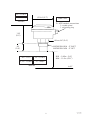
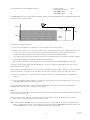
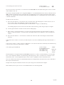
5
IP2046/IM
Nov 2006
-40 / +70°C
IP66 / IP67
2 x M20 conduit connections
1 x cable gland
1 x blanking plug
60mm A/F (2.4")
MSP400RH-B28 : 2" BSPT
MSP400RH-N28 : 2" NPT
MIN : 0.45m (18”)
MAX : 11.0m (433”)
b.rEF
-30 / +70°C
-0,25 / +3,0bar
Ø 144 (5.7")
65
(2.6")
135
(5.3")
-40 / +158°F
-22 / +158°F
-4 / +44psi
Ambient
Wetside

6
IP2046/IM
Nov 2006
3.0 Installation
Important safety notice : The MSP400 is designed for safe area use only, and must not be installed in a
hazardous area, even if the power is supplied through a barrier device.
General
a. Installation must be carried out by suitably trained personnel in accordance with the
applicable code of practice.
b. If the equipment is likely to come into contact with aggressive substances, it is the
responsibility of the user to take suitable precautions that prevent it from being adversely
affected, thus ensuring that the type of protection is not compromised.
Aggressive Substances – e.g. acidic liquids or gases that may attack metals or solvents that may
affect polymeric materials.
Suitable Precautions – e.g. regular checks as part of routine inspections or establishing from the
material’s data sheet that it is resistant to specific chemicals.
c. The equipment should only be cleaned with a damp cloth, do not use solvents.
d. The equipment is not intended to be repaired by the user and is to be replaced by an
equivalent certified unit. Repairs should only be carried out by the manufacturer or
approved repairer.
3.1 Location of the MSP400RH transmitter
Correct location of the transmitter is essential for the reliable operation of any ultrasonic level
measurement system.
Whilst the transmitter may be site tuned to deal with most application conditions, it is strongly
recommended that the following guidelines should be adopted wherever relevant.
3.1.1 General considerations
• The MSP400RH transmitter complies with the European Directive for Electro Magnetic Compatibility
(EMC) Class B.
It is not advisable to mount the transmitter in close proximity to a source of electrical noise such as a
variable speed drive or other high powered electrical device.
• The MSP400 should be mounted above the liquid surface using the “2” thread provided. To
facilitate mounting, a bracket kit is available. See Section 3.2.
Note : The MSP400 is designed to be mounted in a non-metallic fitting or flange. The use of
metallic fittings or flanges is not recommended.
• The transmitter should be mounted as near vertical as possible to ensure a good echo from the liquid
surface and maximum echo size received.
The beam angle (to the half power point) of the transmitter is 12 degrees inclusive.
Obstructions in the tank or well may generate echoes which can be confused with the real liquid
surface echo. Obstructions within the beam angle generate strong “false-echoes”; wherever possible,
the transmitter should be positioned such that false echoes are avoided.
To avoid detecting unwanted objects in the tank or well, it is advisable to maintain a distance of at
least 0.11m from the centre line of the transmitter for every metre range to the obstruction.
• If the transmitter is located near the side of the tank or well, there will be no false echo generated
provided the wall is smooth and free of protrusions. However, there will still be a reduction in the
echo size. To avoid large echo size loss, it is recommended that the transmitter never be mounted
closer than 0.3m to the wall.
Fatty, dirty or viscous liquids can cause a “scum line” to build-up on the tank or well wall. Avoid false
echoes from this by enabling “scum line prevention” software in the MCU control unit.

7
IP2046/IM
Nov 2006
• If the transmitter is mounted in an enclosed tank, avoid mounting the transmitter in the centre of the
tank roof as this could act as a parabolic reflector and create unwanted echoes. Avoid applications
where heavy condensation could form on the transducer face.
• If the transmitter is mounted in a stand-off or nozzle, it is always preferable that the transmitter face
be at least 5mm proud of the stand-off such that it protrudes beyond the stand-off and into the tank.
If this is not possible, see section 3.2.
• If the transmitter is used in environments where direct sunlight can cause very high surface
temperatures on exposed instruments, it is recommended that the installer should construct a
suitable sun-shade to protect against this.
• Remember that the minimum operating range of the transmitter is 0.45m. The transmitter will not
detect any liquid surface closer than 0.45m to the transmitter face.
3.1.2 Liquid surface conditions
• Foaming liquids can reduce the size of the returned echo as foam is a poor ultrasonic reflector. It is
always preferable to mount an ultrasonic transmitter over an area of clear liquid, such as near the
inlet to a tank or well. In extreme conditions, or where this is not possible, the transmitter may be
mounted in a vented stilling tube provided that the inside bore of the stilling tube is at least 100 mm
(4”) and is smooth and free from joints or protrusions. It is also preferable that the bottom of the
stilling tube does not become uncovered, thus preventing the ingress of foams.
• Beware of mounting the transmitter directly over any inlet stream.
• Liquid surface turbulence is not normally a problem unless it is excessive. In most cases, the effects
of turbulence are minor, with excessive turbulence being catered for by fine tuning the transmitter on
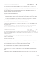
site if necessary.
i.e. D Min = 0.45m (18”)
D Max = 11m (433”)
C = 0.3m (12”) min to 0.88m (36”)
Max 3°
C
0,11m/m
D
(1.3"/ft)

8
IP2046/IM
Nov 2006
It is important to note that the bottom reference of the transmitter should be related to the centre of the
invert of the primary device, NOT the distance to the channel bottom directly below the transmitter.
3.1.3 In-tank effects
• Stirrers or agitators can cause a vortex. Always try to mount the transmitter off-centre of any vortex to
maximise the return echo.
As stirrer blades become uncovered they will create echoes as they pass through the ultrasonic beam.
The transmitter can be tuned to ignore these false echoes on site.
• In non-linear tanks with rounded or conical bottoms, always mount the transmitter off-centre. In some
cases, it may be desirable to install a perforated reflector plate on the tank bottom directly under the
transmitter centre line to ensure a satisfactory return echo.
• Avoid mounting the transmitter directly above any pumps as the transmitter will detect the pump
casing as the liquid falls away. If this is not possible, fine tuning on site may be required to ignore
echoes from the pump casings.
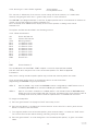
3.1.4 Open Channel Flow installations.
There are normally two distinct parts to an open channel flow measurement system; the primary element
(flow structure) and the secondary element (Head measurement instrumentation).
For accurate open channel flow measurement, both parts of the system must be installed accurately.
This manual explains some key aspects of the installation of the secondary element, in this case the
ultrasonic transmitter.
For full details of the installation of a primary element such as a flume or weir, reference should be made
to the relevant British (BS3680) or International standard.
In the United Kingdom, Mobrey Ltd offers a complete installation and commissioning service for
open channel flow measurement systems. For further information contact the sales office and/or refer to
Mobrey’s ‘The Guide’.
Positioning of the transmitter is critical and should be the correct distance upstream from the flow
structure as stated in BS3680 e.g. a distance of 4 to 5 times Hmax for a thin plate weir or 3 to 4 times
Hmax for a flume.
For optimum accuracy, the front face of the transmitter should be positioned at a height that is at least
equal to the maximum flow depth plus the blanking distance of the transducer. A minimum distance of
0.46m is recommended.
Hmax
Hmax + 0.46m

9
IP2046/IM
Nov 2006
• The liquid surface at the point of measurement must have a stable, smooth surface and uniform
approach velocity. It must not be affected by baffles, foam, hydraulic jumps or any other object
likely to cause flow disruption.
• The primary element should be free from any situation where it is likely to ‘drown’ (refer to relevant
standard for further information)
• The MSP400RH transmitter has integral temperature compensation and must be protected at all
times from direct sunlight and any radiated heat.
For maximum accuracy and stability of level measurement reading the transmitter should always be
shrouded to prevent the incidence of direct sunlight.
If the flow structure permits, mount the transmitter within the flow channel or chamber.
Alternatively, the MSP400RH transmitter can accept an input from an external temperature sensor.
See section 3.3.1.
If you are in doubt about any aspect of transmitter installation, contact Mobrey (Service
Division) who will be pleased to advise.
In addition to the above, when setting the bottom reference on a ‘V’ notch weir it is important that the
true invert of the weir is taken and not the meniscus liquid level, which may be 3 to 4mm (1/8”) above
the true invert.
Flow
Channel invert
Primary device (eg.
flume, weir) invert
Transmitter
front face
Meniscus
True invert
Transmitter bottom
reference

10
IP2046/IM
Nov 2006
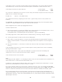
3.2 Mounting the transmitter above the liquid surface.
A 2” thread is provided to mount the transmitter.
The user should check the thread form, which will be either 2” BSPT (MSP400RH-B28) or 2” NPT
(MSP400RH-N28). The thread form is clearly marked on the hexagon of the transducer body.
Note : The MSP400 is designed to be mounted in a non-metallic fitting or flange. The use of metallic
fittings or flanges is not recommended.
To help installation, a bracket kit is available from Mobrey. This comprises a Stainless Steel angle bracket
and PVC threaded disc which may be used to mount the MSP400 on a gantry or other support over the
liquid level. Order part number MSP-BRK2 (BSP) or MSP-BRK3 (NPT). The bracket may be bolted to a
suitable cross member above the liquid surface.
Ensure that the transmitter is perpendicular to the liquid surface to maximise the return echo size.
Check that the maximum liquid level will not encroach into the 0.45m blanking zone of the transmitter.
Note : To aid alignment, the echo size / signal strength can be displayed on the MCU900 control unit or
on the MSP400RH transmitter display. Refer to section 4 for details.
Use PTFE tape on the screw thread, tighten to hand tight + ¼ turn, using the Hexagon.
When installing on a vessel which has a nozzle or stand-off, and the transducer face does not protrude into
the vessel, note the dimensions in the diagram below and always ensure that the nozzle/vessel weld is
smooth and free from internal weld beads or other projections.
Use hexagon to
tighten to hand
tight + ¼ turn
DO NOT USE
HOUSING TO
TIGHTEN.
PTFE
(Teflon)
Max : 0,35m (14")
Min 0,15m (6")
Min :
R3,0mm (1/8")

11
IP2046/IM
Nov 2006
3.3 Wiring
The transmitter is supplied with cable gland suitable for cable sizes 4-8mm diameter.
Terminal 1 : +24V dc
2 : 0v dc
3 : RL1 (SPST)
4 : RL1 (SPST)
5 : RL2 (SPST)
6 : RL2 (SPST)
7 : MSP-RTP temperature probe (if used)
8 : MSP-RTP temperature probe (if used)
Earth Screen : Connect to a standard earth in the control room.
3.3.1 External temperature sensor
The MSP400RH transmitter will accept an input from a Mobrey external temperature sensor.
Order part number MSP-RTP.
This is a thermistor based temperature sensor specifically designed for use with the MSP400RH
transmitter.
Full installation instructions are supplied with the temperature sensor, but note that it should be mounted
out of direct sunlight in a position such that it can give a representative reading of the air temperature
between the liquid surface and the MSP400RH transmitter.
3.3.2 After completing the wiring
Ensure all cable glands / blanking plugs and seals are in good condition after wiring to maintain the
weatherproof rating of the transmitter.
Check that the cover seal is in good condition and not twisted or misaligned in the seal location groove.
When replacing the cover, tighten the 3 cover screws evenly to exert uniform pressure on the cover seal.
Max 3000m (9845ft)
Ø 4 - 8mm
(0.15 - 0.31")
+12-40V dc
0V
Twisted pair, screened
Min 0,22mm
2
(25 SWG / 24 AWG)
Max 1,5mm
2
(17 SWG / 15 AWG)
Earth screen in
control room only

12
IP2046/IM
Nov 2006
3.3.3 Relays
The MSP400RH transmitter has 2 integral relays which may be used for control purposes. These relays
are light duty and should be used as signal relays only, with control functions being performed by external
control relays.
Relay 2 is defaulted as a ‘fault’ relay, normally energised, but may be reconfigured on site as a set point
relay if required.
3.4 Additional components in the two wire loop.
3.4.1 Lightning / surge protection and other loop devices
It is allowable to fit loop powered or separately powered devices in the two wire loop provided that the
transmitter receives a minimum voltage of 12V dc at 21 mA loop current.
If the area is prone to lightning strikes or voltage surges, fitting of a suppressor device is desirable
between the transmitter and the control unit.
3.5 Wiring to allow HART communication
If it is intended to use HART digital communications with the MSP400RH transmitter, a 250 Ohm 0.25W
load resistor must be installed in the loop.
When used with the Mobrey MCU900 family of Control Units, there is no need to install an
external load resistor in the loop as there is a suitable resistor built in to the Control Unit.
If the transmitter is being supplied through a safety barrier, ensure the type chosen will pass HART/
SMART information.
Once installed, a HART communicator can be connected across the load resistor, or across the loop at
any point downstream of the load resistor.

13
IP2046/IM
Nov 2006
4.0 Commissioning, programming and operation
The MSP400 operates from a menu of parameters, each held in a specific memory location within the
instrument. The memory locations may be pictured as a matrix, and the user navigates to each parameter
to programme the instrument using ↓ and → steps.
Refer now to the Main Menu structure shown in Appendix A
The MSP400 leaves the factory pre-programmed with a value in each parameter location such that , when
the power is first applied, the instrument will give a sensible reading. A list of default values is given in
the parameter listing in Appendix B.
The MSP400 is HART enabled, allowing remote communications with the instrument.
The instrument can therefore be either programmed using a suitable HART compatible master, or may be
programmed locally using the push buttons provided inside the instrument. For details of local
programming, continue reading this section. For details of HART communications, refer to Appendix D.
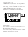
4.1 Display and push buttons.
Button Colour : Green Blue Red
The main display allows display of up to 5 characters, which in the normal run mode will be the
measurement, termed the Primary Variable (PV) of the instrument, or in the programming mode will be
data to assist in programming.
To the left of the main display are 4 arrow icons, only one of which will be illuminated at any one time to
indicate the duty chosen by the user.
To the right of the main display are 2 arrow icons which indicate the status of the transmitter relays.
When illuminated, they indicate that the relay contact is closed.
Under the main display is a text string which allows display of the units of measurement. The instrument
will illuminate only those characters applicable to the units of measurement chosen.
To the right of the text string is an echo received icon made up of 3 arc segments which continuously
indicate the strength of the echo received (minimum, average and good)
gal/m
3
/hrft
3
/hringal/s @max
↓↓↓
→→→
↵↵↵
D
L
C
F
Alarm
Fault

14
IP2046/IM
Nov 2006
4.2 Power up
On power up, the MSP400 will take a few seconds to initialise. The display will run through a set-up
routine, first illuminating all display characters then showing the software revision number. Once checks
are complete, the display will show the Primary Variable (PV) determined based upon the factory default
values in the memory.
On a new instrument aimed at a good target, this will be what the MSP400 calculates as a level reading
based upon the default value for the bottom reference.
The duty icon against the letter L on the top plate and the RL2 icon will be illuminated.
It is possible that the RL1 icon may be illuminated depending upon the level calculated by the MSP400
at this time.
The MSP400 is now ready for use, and the next step is to programme the unit with details of the
application.
The MSP400 may be programmed either in-situ or prior to installation. All programmed data is retained in
the MSP400 memory after power off.
4.3 Programming- Important notes to help you programme the MSP400
• Do not allow rain or water to enter the MSP400 whilst programming or damage to the circuit boards
will occur.
• Use the push buttons as instructed below to navigate through the programming menu and select or
enter application data.
It is recommended that use of the push buttons is firm but not overly so to prevent damage to the
circuit boards below, and that the user should not press buttons too fast to avoid incorrect data entry.
Simply holding down the green button ↓ will automatically scroll through any option list without the
need for repeated pressing of the button.
• Pressing the red button ↵ at any time will step the user back to the previous level in the menu.
Note, if the red button ↵ is pressed after a menu option selection has been made or new data has
been entered, this option selection or new data will automatically be saved.
• Whilst programming should be simple and intuitive, it may be that the user wishes to start again or
may wish to clear the memory of site entered data from a previous application. The MSP400 has a
“re-set default values” routine which allows the user to reload the MSP400 memory with the factory
default values as shown on the menu structure. Refer to section 4.7.10.

15
IP2046/IM
Nov 2006
4.4 Setting up for the chosen application - the Main Menu.
Refer now to the main menu structure chart in Appendix A.
It is important to note that MSP400 programming is most easily accomplished by first selecting the duty
the transmitter is to perform.
Once a duty is selected (see section 4.4.1), a “mini-wizard” programming assistant is invoked and the
user is thereafter only asked for information relevant to the duty chosen. As the user is guided through the
menu, data input allows the mini-wizard to populate relevant parameters with application specific data in
the background, and then select the next step required to configure the transmitter for the chosen
application.
The user is strongly advised to enter the duty menu whenever programming the MSP400, thus invoking
the mini-wizard which will assist programming.
Once programmed, it is possible to review the data entered into or calculated by the MSP400 by stepping
through the main menu using the green button ↓.
Note however that this will be a manual navigation of the MSP400 menu, and that
all
menu items will be
shown in this procedure, regardless of the duty chosen; the mini-wizard is only invoked if the user enters
and scrolls through or selects/refreshes a duty choice.
In a manual navigation down the main menu, simply ignore those menu items shown that do not relate to
your application.
4.4.1 Selecting the duty: Screen display: dutY
Factory default setting: Level
The MSP400 may be programmed to perform one of 4 duties:
• Distance measurement
• Level measurement (factory default setting)
• Flow measurement
• Contents measurement
To change the duty:
a) Press the green button ↓ to display the “dutY” menu entry screen.
b) To confirm or change the duty from Level to one of the other duties, thus invoking the mini-wizard,
press the blue button → to enter the “dutY” menu. Press the blue button → again to allow change of
the duty. The current duty will now be flashing, indicating it may be confirmed or changed.
c) Press the green button ↓ to scroll through the list of available duty options, or press the red button ↵ if
the duty displayed is correct
d) Once the desired duty is shown (flashing) on the display, press the blue button → to select this duty. It
will now stop flashing.
e) If the chosen duty is incorrect, the edit sequence for the duty can be re-started by pressing the blue
button → again.
If the chosen duty is correct, press the red button ↵ to save the duty to memory and automatically
scroll on to the next main menu option: units.
Note that the arrow icon to the left of the display will now show the duty chosen and saved.

16
IP2046/IM
Nov 2006
4.4.2 Selecting the units of measurement Screen display: unitS
Factory default setting:
MSP400RH-B28 m
MSP400RH-N28 ft
i) Note that the factory default units of measurement are dictated by the model type, which may be
Imperial (ft) or Metric (m).
The user can reconfigure a Metric unit to be an Imperial or vice-versa by changing the base units (b.unit)
of the MSP400 - refer to section 4.7.11
ii) Note that changing the base units will cause the MSP400 to re-start with factory default values in all
other parameters.
Changing base units after programming the MSP400 will cause all programmed data to be overwritten
with factory default values.
The MSP400 is pre-programmed with selected units of measurement for each of the duties available :
• Distance and Level measurement
m , ft, in, none
• Flow measurement
l/s, l/m, m
3
/hr, gal/s, gal/m, ft
3
/m (cfm), ft
3
/hr, none
• Contents measurement
l, m
3,
gal, ft
3
To change the units of measurement:
a) Press the green button ↓ to display the “unitS” menu entry screen. If metres are the chosen units of
measurement, as indicated by the small “”m” below the word “unitS” press the green button ↓ to
continue commissioning.
b) To change the units of measurement from metres to one of the other options, press the blue button →
to enter the “unitS” menu. Press the blue button → again to allow change of the units of
measurement. The current unit of measurement will now be flashing, indicating it may be changed.
c) Press the green button ↓ to scroll through the list of available duty options.
Notes.
i) The MSP400 will offer a selection of units of measurement relevant to the chosen duty as shown in the
option table above.
The final option in each set is “none”, which appears as a blank screen. This option is available to the
user who requires to display in units other than those available in the standard option table. In this case,
the user will need to scale the PV according to a suitable scaling factor - refer to section 4.4.6
It is strongly recommended that the user make a note of the scale factor and the resultant units of
measurement and retain this on a label within the instrument at all times to avoid later confusion.
ii) When using the green button ↓ to scroll through the units of measurement options, allow 2-3 seconds
after each button press for the MSP400 to check and display the selection. Pressing the green button ↓
continuously simply continues scrolling around the units of measurement option loop.
d) Once the desired unit of measurement is shown (flashing) on the display, press the blue button → to
select this option. It will now stop flashing.
e) If the chosen units of measurement are incorrect, the edit sequence for the units of measurement
can be re-started by pressing the blue button → again.
If the chosen units of measurement are correct, press the red button ↵ to save the units of measurement
to memory and automatically scroll on to the next main menu option: b.rEF.

17
IP2046/IM
Nov 2006
4.4.3 Setting the correct bottom reference Screen display: b.rEF
Factory default value:
MSP400RH-B28 11
MSP400RH-N28 36
The MSP400 leaves the factory with the bottom reference pre-programmed to the maximum range of the
instrument, either 11m or 36ft.
To change the bottom reference:
a) Press the green button ↓ to display the current “b.rEF” menu entry screen.
b) Press the blue button → to enter the “b.rEF” menu and to display the current bottom reference in use.
It is quite unlikely that the factory default value for bottom reference will suit your application.
To edit the bottom reference, press the blue button → to enter the editing mode.
The leading digit of the current bottom reference will now be flashing, indicating it may be changed.
c) Use the green button ↓ to edit the value of the leading digit.
Be careful not to enter a value greater than the maximum range of the MSP400: 11m or 36ft.
The value of the leading digit should therefore be 1 or 3 as a maximum, depending upon the units of
measurement chosen earlier.
Once correct, use the blue button → to select the next digit and then the green button ↓ to edit as before,
or the blue button → to move to the next digit. Continue this sequence until all 5 digits are correct.
d) Press the blue button → a final time to confirm the new value. None of the digits should now be
flashing.
e) If the new bottom reference value is incorrect, the edit sequence for the bottom reference can be re-
started by pressing the blue button → again.
If the new bottom reference is correct, press the red button ↵ to save the new value to memory and
automatically scroll on to the next main menu option:
Note:
If the user has chosen a duty of Flow or Contents, the next menu option offered will be “ProF”. Refer now
to sections 4.4.4 to 4.4.9.
If the user has chosen a duty of Level or Distance, the next menu option offered will be “4”. Skip
sections 4.4.4 to 4.4.9 and refer now to section 4.4.10.
TIP
: a feature of the MSP400 useful at this stage is that it can be used as an electronic tape measure.
With an empty tank or vessel, select Distance as the duty and the MSP400 will read the distance to
the bottom of the tank. This can be noted and used when setting b.rEF
ullage
liquid
level
b.rEF
20/4
4/20

18
IP2046/IM
Nov 2006
4.4.4 Selecting the correct Profile algorithm. Screen display: ProF
Factory default value: Linear
This selection is offered only if the user has chosen a duty of Flow or Contents, or is shown when
manually navigating the main menu - ignore if duty chosen is Level or Distance.
The MSP400 is pre-programmed with a selection of popular profiles which are mathematical formulae to
convert a linear level reading to a flow or volumetric PV.
Once converted, the 4-20mA and the display of the unit will operate according to the flow or
volumetric PV.
The options available are described in the following sections:
4.4.4.1 Flow measurement
3/2 Flume 3/2 flow law
5/2 V-Notch 5/2 flow law
mann Manning formula
PAr 1 1 ft Parshall flume
PAr 2 2 ft Parshall flume
PAr 3 3 ft Parshall flume
PAr 4 4 ft Parshall flume
PAr 5 5 ft Parshall flume
PAr 6 6 ft Parshall flume
PAr 7 7 ft Parshall flume
PAr 8 8 ft Parshall flume
FF01 Flume Flat 1
:
:
:
FP07 Flume Parabolic 7
The last 30 options for flow FF01 - FP07 comprise a selection of pre-defined standard
flow structures which may be of use if none of the other profiles suit. Refer to Appendix
D for details.
Note, when scrolling around the profile option loop, all flow and contents profiles are shown.
There are two other profiles which are available but which are not visible when
programming the MSP400 using the push buttons.
SPEC. P Special plotted : only used if the MSP400 has been configured by a HART master such as
the Mobrey MCU900 series controller or Mobrey H-Conf401 software
SPEC.C Special calculated : used when a standard profile is not available from the MSP400 library.
Allows the user to enter a Power law and a K factor, for example for a small Parshall flume or
to modify the K factor or power to allow for imperfections in standard flow structures.
To change the flow profile:
a) Press the green button ↓ to display the “ProF” menu entry screen.
b) Press the blue button → to display the current selection. If this selection is correct, press the red
button ↵ to return to the main menu.
c) To change the profile to one of the other options, press the blue button → to enter the “ProF” menu.
The current selection will now be flashing, indicating it may be changed.
d) Press the green button ↓ to scroll through the list of available profile options, as given in the table
above.

19
IP2046/IM
Nov 2006
Note: The complete range of options is displayed, regardless of the duty selected earlier.
e) Once the desired profile is shown (flashing) on the display, press the blue button → to select this
option. It will now stop flashing.
f) If the chosen profile is incorrect, the edit sequence for the profile selection can be re-started by
pressing the blue button → again.
If the profile is correct, press the red button ↵ to save the profile to memory and automatically scroll on
to the next main menu option.
Note:
The next menu item presented will depend upon the flow profile chosen :-
i) 3/2 5/2 : the next menu item will be “SCALE”
The MSP400 will automatically calculate the Power factor and only requies the K factor to be
entered.
Refer to section 4.4.6
ii) Manning : the next menu item will be “LEUEL @ max”.
Refer to section 4.4.7.
iii) Parshall, FF or FP : the next menu item will be “d”. The MSP400 will automatically calculate the
appropriate Power factor and K factor, and will set the 4mA point at zero flow and the 20mA point
at maximum flow.
Refer to section 4.4.12.
4.4.4.2 Contents measurement
Lin Linear (factory default setting)
H.CYL.F Horizontal cylinder on it’s side with flat ends
SPH. Spherical vessel
H.CYL.D Horizontal cylinder on it’s side with dished ends
To change the contents profile:
a) Press the green button ↓ to display the “ProF” menu entry screen.
b) Press the blue button → to display the current selection. If this selection is correct, press the red
button ↵ to return to the main menu.
c) To change the profile to one of the other options, press the blue button → to enter the “ProF” menu.
The current selection will now be flashing, indicating it may be changed.
d) Press the green button ↓ to scroll through the list of available profile options, as given in the table
above.
Note: The complete range of options is displayed, regardless of the duty selected earlier.
e) Once the desired profile is shown (flashing) on the display, press the blue button → to select this
option. It will now stop flashing.
f) If the chosen profile is incorrect, the edit sequence for the profile selection can be re-started by
pressing the blue button → again.
If the profile chosen is “Lin”, press the red button ↵ to save the profile to memory and automatically
scroll on to the next main menu option “SCALE”.
Refer to section 4.4.6.

20
IP2046/IM
Nov 2006
If the profile chosen is any other contents profile, press the red button ↵ to save the profile to memory
and automatically scroll on to the next main menu option “Cont @ max”, Refer to Section 4.4.9.
4.4.5 Power factor for the chosen flow law. Screen display: P.FACt
Factory default value: 1.000
This selection is offered only if the user has chosen a duty of Flow which requires the manual entry of a
power factor in a formula of the type
Flow Q = kh* (where * = the power factor)
or is shown when manually navigating the main menu - ignore if duty chosen is Level, Distance or
Contents.
The MSP400 is pre-programmed with the appropriate power factor for many of the flow profile options
available, or it may be edited to suit the user’s specific flow structure.
Refer to Appendix C for a table of pre-programmed values.
To edit the power factor
a) Press the blue button → to enter the “P.FACt” menu and to display the current power factor in use. If
this is correct, press the green button ↓ return to the main menu.
If the power factor is to be edited, press the blue button → again to allow editing
The leading digit of the current power factor will now be flashing, indicating it may be changed.
b) Use the green button ↓ to edit the value of the leading digit.
c) Once correct, use the blue button → to select the next digit and then the green button ↓ to edit as
before, or the blue button → to move to the next digit. Continue this sequence until all 5 digits are
correct.
d) Press the blue button → a final time to confirm the new value. None of the digits should now be
flashing.
If the new power factor value is incorrect, the edit sequence for the power factor can be re-started by
pressing the blue button → again.
If the new power factor is correct, press the red button ↵ to save the new value to memory and
automatically scroll on to the next main menu option: “SCALE”
4.4.6 K Factor for the chosen flow law Screen display SCALE
Factory default value 1.000
Note:
The display will read “SCALE”. If a flow duty has been chose, the value entered into this parameter is in
effect the K factor in a flow law of the form Flow Q = kh*.
If a Distance, Level or Contents duty has been chosen, the value entered into this parameter is a factor
by which the measured distance, level or contents is scaled.
For a Level or Distance duty the scaling factor is normally left at the value calculated by the MSP400
depended upon previously entered data and the duty chosen, or the default value of 1.000, unless the user
wishes to convert the measurement to units other than those offered as standard, for example, yards.
For a linear Contents duty, the user must enter a scaling factor to convert the level measurement to a
contents measurement. If the units of measurements are “m”, then enter the volume contained in 1m of
liquid height in the tank. If the units of measurements are “ft”, then enter the volume contained in 1ft of
liquid height in the tank.
Page is loading ...
Page is loading ...
Page is loading ...
Page is loading ...
Page is loading ...
Page is loading ...
Page is loading ...
Page is loading ...
Page is loading ...
Page is loading ...
Page is loading ...
Page is loading ...
Page is loading ...
Page is loading ...
Page is loading ...
Page is loading ...
Page is loading ...
Page is loading ...
Page is loading ...
Page is loading ...
Page is loading ...
Page is loading ...
Page is loading ...
Page is loading ...
Page is loading ...
Page is loading ...
Page is loading ...
Page is loading ...
-
 1
1
-
 2
2
-
 3
3
-
 4
4
-
 5
5
-
 6
6
-
 7
7
-
 8
8
-
 9
9
-
 10
10
-
 11
11
-
 12
12
-
 13
13
-
 14
14
-
 15
15
-
 16
16
-
 17
17
-
 18
18
-
 19
19
-
 20
20
-
 21
21
-
 22
22
-
 23
23
-
 24
24
-
 25
25
-
 26
26
-
 27
27
-
 28
28
-
 29
29
-
 30
30
-
 31
31
-
 32
32
-
 33
33
-
 34
34
-
 35
35
-
 36
36
-
 37
37
-
 38
38
-
 39
39
-
 40
40
-
 41
41
-
 42
42
-
 43
43
-
 44
44
-
 45
45
-
 46
46
-
 47
47
-
 48
48


Emerson Transmitter IP2046IM User manual
- Category
- Measuring, testing & control
- Type
- User manual
Ask a question and I''ll find the answer in the document
Finding information in a document is now easier with AI
Related papers
Other documents
-
Sekonda M CLASSIQUE SILVER DIAL CHRONO W User manual
-
Tecfluid SERIES LU Instructions Manual
-
ALLEGION RC-04 ISONAS Reader Controll User guide
-
-
Micronics 204 User manual
-
-
 Badger Meter iSonic 2000 User manual
-
Emerson Process Management MSP900SH User manual
-
-
Rosemount 3100 Series Ultrasonic Liquid Level Owner's manual
