Page is loading ...

xx
Contacting Tektronix
Tektronix, Inc., 14150 SW Karl Braun Drive, P.O. Box 500,
Beaverton, OR 97077, USA
For product information, sales, service, and technical support:
In Nor
th America, call 1-800-833-9200.
Worldwide, visit www.tek.com to find contacts in your area.
Important safety information
This manual contains information and warnings that must be
followed by the user for safe operation and to keep the product
in a safe condition. To safely perform service on this product,
additional information is provided at the end of this section.
General safety summary
Use the product only as s pecified. Review the following safety
precautions to avoid injury and prevent damage to this product
or any products connected to it. Carefully read all instructions.
Retain these instructions for future reference.
Comply with local and national safety codes.
For co
rrect and safe operation of the product, it is essential that
you follow generally accepted safety procedures in addition to
the sa
fety precautions specified in this manual.
The product is designed to be used by trained personnel only.
Only qualified personnel who are aware of the hazards involved
should remove the cover for repair, maintenance, or adjustment.
Befor
e use, always check the product with a known source to
be sure it is operating correctly.
This product is not intended for detection of hazardous voltages.
Use personal protective equipment to prevent shock and arc
blast injury where hazardous live conductors are exposed.
While using this product, you may need to access other parts
of a l
arger system. Read the safety sections of the other
component manuals for w arnings and cautions related to
oper
ating the system.
When incorporating this equipment into a system, the safety of
that system is the responsibility of the assembler of the system.
To avoid fire or personal injury
Use proper power cord. Use only the power cord specified for
this product and certified for the country of use.
Do not use the provided power cord for other products.
Ground the product. This product is grounded through the
grounding c
onductor of the power cord. To avoid electric
shock, the grounding conductor must be connected to earth
ground. Bef
ore making connections to the input or output
terminals of the product, ensure that the product is properly
grounded.
Do not disable the power cord grounding connection.
Power disconnect. The power cord disconnects the product
from the power source. See instructions for the location. Do
not position the equipment so that it is difficult to access the
power cord; it must remain accessible to the user at all times to
allow for quick disconnection if needed.
Connect and disconnect properly. Do not connect or disconnect
probes or test leads while they are connected to a voltage
source.
Use only insulated voltage probes, test leads, and adapters
supplied with the product, or indicated by Tektronix to be
suitable for the product.
Observe all terminal ratings. To avoid fire or shock hazard,
observe all ratings and markings on the product. Consult the
product m anual for further ratings information before making
connections to the product. Do not exceed the Measurement
Category (CAT) rating and voltage or current rating of the
lowest rated individual component of a product, probe, or
accessory. Use caution when using 1:1 test leads because the
probe tip voltage is directly transmitted to the product.
Do not appl
y a potential to any terminal, including the common
terminal, that exceeds the m aximum rating of that terminal.
Do not float the common terminal above the rated voltage for
that terminal.
Do not operate without covers. Do not operate this product with
covers or panels removed, or with the case open. Hazardous
voltage exposure is possible.
Avoid exposed circuitry. Do not touch exposed connections
and components when pow er is present.
Do not operate with suspected failures. If you suspect that
there is damage to this product, have it inspected by qualifi
ed
service
personnel.
Disable the product if it is damaged, Do not use the product if it
is damaged or operates incorrectly. If in doubt about safety of
the product, turn it off and disconnect the power cord. Clearly
mark the product to prevent its further operation.
Before use, inspect voltage probes, test leads, and accessories
for mecha
nical damage and replace when damaged. Do not use
probes or test leads if they are damaged, if there is exposed
metal, or
if a wear indicator shows.
Examine the exterior of the product before you use it. Look
for cracks or missing pieces.
Use only specified replacement parts.
Do not operate in wet/damp conditions. Be aware that
condensation may occur if a unit is moved from a cold to a
warm environment.
Do not operate in an explosive atmosp here.
Keep product s urfaces clean and dry. Remove the input signals
before you clean the product.
Provide proper ventilation. To ensure proper cooling, keep the
sides and rear of the instrument clear of obstructions. Slots
and openings are provided for ventilation a nd should never
be covered or otherwise obstructed. Do not push objects into
any of the openings.
Provide a s afe working environment. Always place the product
in a location convenient for viewing the display a nd indicators.
Avoid improper or prolonged use of button pads. Be sure your
work area meets applicable ergonomic standards.
Probes and test leads
Before connecting probes or test leads, connect the power cord
from the power connector to a properly grounded power outlet.
Keep fingers behind the finger guards on the probes.
Remove all probes, test leads and accessories that are not in use.
Use only correct M easurement Category (CAT), voltage,
temperature, altitude, and amperage rated probes, test leads,
and adapters for any measurement.
Beware of high voltages. Understand the voltage ratings for
the probe you are using and do not exceed those ratings. Two
ratings are important to know and understand:
The maximum measurement voltage from the probe tip
to the probe r
eference lead
The m aximum floating voltage from the probe reference
lead to earth ground
These two voltage ratings depend on the probe and your
application. Refer to the Specifications section of the manual
for more information.
WARNING. To prevent electrical shock, do not exceed the
maximum measurement or maximum floating voltage for
the oscilloscope input BNC c onnector, probe tip, or probe
reference lead.
Connect and disconnect properly. Connect the probe output
to the measurement product before connecting the probe
to the c ircuit under test. Connect the probe reference lead
to the circuit under test before connecting the probe input.
Disconnect the probe input and the probe reference lead from
the circuit under test before disconnecting the probe from the
measurement product.
Connect and disconnect properly. De-energize the circuit under
test before connecting or disconnecting the current probe.
Connect the
probe reference lead to earth ground only.
Do not connect a current probe to any wire that carries voltages
above the current probe voltage rating.
Inspect the probe and accessories. Before each use, inspect
probe and accessories for damage (cuts, tears, or defects in
the probe body, accessories, or cable jacket). Do not use if
damaged.
Service s a
fety summary
The Service safety summary section contains additional
informati
on required to safely perform service on the product.
Only qualified personnel should perform service p rocedures.
Read this S
ervice safety summary and the General safety
summary before performing any service procedures.
To avoid electric shock. Do not touch exposed connections.
Do not service alone. Do not perform internal service or
adjustmen
ts of this product unless another person capable of
rendering first aid and resuscitation is present.
Disconnect power. To avoid electric shock, switch off the
product p
ower and disconnect the power cord from the mains
power before removing any covers or panels, or opening the
case for s
ervicing.
Use care w
hen servicing with power on. Dangerous voltages
or currents may exist in this product. Disconnect power,
remove ba
ttery (if applicable), and disconnect test leads
before removing protective panels, soldering, or replacing
componen
ts.
Verify sa
fety after repair. Always recheck ground continuity
and m ains dielectric strength after performing a repair.
Terms in product manuals
These terms may appear in the product manuals:
WARNING. Warning statements identify conditions or
practices that could result in injury or loss of life.
CAUTION. Caution statements identify conditions or
practices that could result in damage to this product or
other property.
Symbols an d terms on the product
These terms may appear on the product:
DANGER indicates an injury hazard immediately
accessi
ble as you read the marking.
WARNING indicates an injury hazard not immediately
accessible as you read the marking.
CAUTION indicates a hazard to property including the
product.
When this symbol is marked on the product, be
sure to consult the manual to find out the nature of
the pote
ntial hazards and any actions which have
to be taken to avoid the m. (This symbol may also
be used to refer the user to ratings in the manual.)
The following symbol(s) may appear on the product:
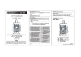
TBS2000B Series Oscilloscopes
Safety and In stallation
ZZZ
Instruct
ions
x
*P0713
63500*
071-3635-00

Operating requirements
Environment requirements
Characteristic Description
Operating
temperature
0°Cto+50°C,with5°C/minutemaximum
gradient, noncondensing (NC), up to
3000 meter altitude
Operating
humidity
5% to 95% relative humidity (% RH) up to
+30 °C
5% to 60% RH above +30 °C up to +50 °C, NC
Operating
altitude
Up to 3000 meters (9842 feet)
Power requirements
Characteristic Description
Power source
voltage
100 V
AC
–240V
AC
±10% RMS, single phase
Power source
frequency
50/60 Hz over entire source voltage range
400 Hz (360 Hz to 440 Hz) for 115 V
AC
(100 V
AC
–
132 V
AC
) RMS source voltage range
Power
consumption
All models: 80 W maximum
Installa
tion
Power on t
he unit
Connect the supplied power cord to the rear-panel power
connector. Push the front panel power button to power the
oscilloscope on and off. To completely remove power from the
unit, disconnect the power cord.
Controls and connections
Read the TBS2000B Series User Manual for detailed
information about all product controls, the user interface, how
to take measurements, and warranty information. The m anual
is available i n the languages listed below.
Language Tektronix part number
English 077-1525-00
French 077-1526-00
German
077-1527-00
Italian 077-1529-00
Spanish
077-1530-00
Korean 077-1532-00
Japanese 077-1533-00
Simp
lified Chinese
077-1534-00
Traditional Chinese
077-1535-00
Russian 077-1536-00
Front pa nel
NOTE. Some control and connector positions are different
between the two- and four-channel models, but their functions
are the same.
1. Use the Navigation controls to select menu items, set
values, display and move cursors, magnify a section of the
waveform and add marks (tags) to a waveform record. The
Mark functions are not now enabled, but will be available
in a future software update.
2. Use the Resource controls to open menus to select and
display automated measurements; save or recall setups,
waveforms, and screen images; set UI language, date and
time, network and Wi-Fi settings, and more.
3. Use the Trigger controls to set the trigger type, source
channel, trigger signal coupling, the signal’s trigger slope
(positive or negative), trigger level, and more.
4. Use the Horizontal controls to set the acquisition mode,
waveform rec
ord length, horizontal scale (time per major
horizontal graticule and samples/second), and more.
5. Use the USB 2.0 Host port to insert a USB flash drive to
save and recall screen im age s, waveforms, and settings,
and install new oscilloscope firmware.
6. Use the TekVPI
®
probe inp ut connectors to connect the
oscilloscope to the signal. The maximum measurement
input voltage is 300 V
RMS
,CATII.
A
symbol next to a m easurement readout indicates a
signal over range condition (clipping). This is often caused
by waveforms that extend above or below the screen edge.
To get an accurate measurement readout, adjust the vertical
scale and/or position knob to show the e ntire waveform
on the screen.
7. Use the Vert ical controls to select a waveform to display,
open menus t
o set signal coupling, bandwidth, probe
attenuation and type; move the waveform up or down on
the screen;
set the vertical scale factor (volts per vertical
graticule division); and more.
Rear panel
1. Aux Out. Sends a low to high transition when a trigger
occurs, to synchronize other test equipment.
2. LAN. Connects to a 10/100 Base-T local area network for
remote access.
3. US B (Host). Connects to the optional Wi-Fi adapter for
wireless remote access.
4. USB (Device). Connects to a PC for remote control using
USBTMC protocol.
Cleaning
Use a dry, soft cotton cloth to clean the outside of the unit.
Do not use any liquid cleaning agents or c hemicals that could
damage the case, controls, screen, markings or labels, or
possibly infiltrate the case.
Compliance
This sect
ion lists the EMC (electromagnetic compliance),
safety, a nd environmental standards with which the instrument
complies
. This product is intended for use by professional and
trained personnel only; it is not designed for use in households
or by chil
dren.
Questions about he following compliance information may be
directed to the following address:
Tektronix, Inc.
PO Box 500, MS 19‐045
Beaverton, OR 97077, USA
www.tek.com
EMC com pliance
EC declaration of conformity – EMC
Meets intent of Directive 2014/30/EC for Electromagnetic
Compatibility. Compliance was demonstrated to the following
specifications as listed in the Official Journal of t he European
Communities:
EN 6 1326-1, EN 61326 -2-1. EMC requirements for electrical
equipment for measurement, control, and laboratory use.
123
45
CISPR 11 (Group 1, Class A)
IEC 61000-4-2; IEC 61000-4-3; IEC 61000-4-4;
IEC 6100
0-4-5; IEC 61000-4-6; IEC 61000-4-11
EN 61000-3-2:A1/A2; EN 61000-3-3
1
This product is intended for use in nonresidential areas only. Use in residential
areas may cause electromagnetic interference.
2
Emissi
ons that exceed the levels required by this standard may occur when
this equipment is connected t o a test object.
3
Equipment may not meet the immunity requirements of applicable listed
standards when test leads and/or test probes are connected.
4
For compliance with the EMC standards listed here, high quality shielded
interface cables that incorporate low impedance connection between the cable
shield and the connector shell s hould be used.
5
10 mV/division to 1 V/division: ≤1.0 division waveform displacement or
≤2.0 di
vision increase in peak-to-peak noise is allowed when the instrument
is subjected to fields and signals as defined in the IEC 61000-4-3 and
IEC 61
000-4-6 tests.
Australia / New Zealand declaration of conformity – EMC
Complies with the EMC provision of the Radiocommunications
Act per the following standard, in accordance with ACMA:
CISPR 11. Radiated and Conducted Emissions, Group
1, Class A, in
accordance with EN 61326-1 and EN
61326-2-1.
FCC – EMC
Emissions are within the limits of FCC 47 CFR, Part 15,
Subpart B for Class A equipment.
Russian Federation
This product is approved by the Russian government to carry
the GOST mark.
Safety complia nce
This sectio
n lists the safety standards with which the product
complies and other safety compliance information.
EC declaration o f conformity – low voltage
Compliance was demonstrated to the following specification as
listed in the Official Journal of the European Union:
Low Voltage D irective 2014/35/EU.
EN 61010-1; EN 61010-2-030
U.S. nationally recognized testing laboratory listing
UL 61010-1
; UL 61010-2-030
Canadian certification
CAN/CSA-C22.2 No. 61010-1; CAN/CSA-C22.2 No.
61010-2-030
Additional compliances
IEC 61010-1; IEC 61010-2-030
Equipmen
ttype
Test and measuring equipment.
Safety class
Class 1 - grounded product.
Pollution degree rating
Pollution Degree 2 (as defined in IEC 61010-1). Rated for
indoor, dry location use only.
Measurement and overvoltage category de scriptions
Measurem
ent t erminals on this product may be rated for
measuring mains voltages from one or more of the following
categori
es (see specific ratings marked on the product and in
the manual).
Category II. Circuits directly connected to the building wiring
at utilization points (socket outlets and similar points).
NOTE. Only measurement circuits have a measurement
category rating. Only mains power supply circuits have an
overvoltage category rating. Other circuits within the product
do not have either rating.
Mains overvoltage category rating
Overvoltage category II (as defined in IEC 61010-1).
Environmental con siderations
This sec
tion provides information about the environmental
impact of the product.
Restriction of hazardous substances
Complies with RoHS2 Directive 2011/65/EU.
Product end-of-life handling
Observe the following guidelines when recycling an instrument
or component:
Equipment recycling. Production of this equipment required
the extraction and use of natural resources. The equipment may
contain substances that could be harmful to the e nvironment or
human health if improperly handled at the product’s end of life.
To avoid release of such substances into the environment a nd
to reduce the use of natural resources, we encourage you to
recycle this product in an appropriate system that will ensure
that most of the materials are reused or recycled appropriately.
This symbol indicates that this product complies
with the applicable European Union requirements
according to Directives 2012/19/EU and
2006/6
6/EC on waste electrical and electronic
equipment (WEEE) and batteries. For information
about recycling options, check the Tektronix Web
site (www.tek.com/productrecycling).
Copyright © Tektronix, Inc. All rights reserved. www.tek.com
/