DMP Electronics 1100d Installation guide
- Category
- Security access control systems
- Type
- Installation guide

DESCRIPTION
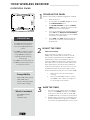
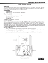
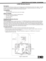
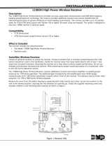
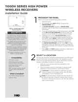
Figure 1: 1100D Wireless Receiver
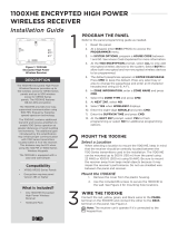
1
PROGRAM THE PANEL
Refer to the panel programming guide as needed.
1. Reset the panel.
2. At a keypad, enter 6653 (PROG) to access
the PROGRAMMER menu.
3. In SYSTEM OPTIONS, program a HOUSE
CODE between 1 and 50. See House Code
Explained for more information.
4. If you're programming an XT50 Series panel,
select NO at the BUILT IN 1100 WIRELESS
prompt to allow the panel to use the 1100D
for wireless communication.
5. Press CMD until STOP displays and press
a select key or area to save and exit the
Programmer.
The 1100D Wireless Receiver
provides up to 32 wireless
zones for XT30/XT50 Series
panels.
The 1100D provides Two-Way,
supervised communication
using 900 MHz frequency
hopping spread spectrum
technology.
The 1100D can be mounted up
to 500 feet (152 meters) from
the panel enclosure.
Compatibility
• DMP XT30 Series panels
• DMP XT50 Series
panels running firmware
Version 102 or higher
What is Included
• One 1100D Wireless
Receiver
• Hardware Pack
2
MOUNT THE 1100D
Select a Location
When selecting a location to mount the
1100D, keep in mind that the receiver should
be centrally located between the 1100 Series
transmitters used in the installation and no
more than 500 feet (152 meters) away from the
panel. Be sure to mount the receiver away from
large metal objects because it may impair the
receiver’s performance. Also, be sure to not use
shielded wire between the panel and receiver.
Follow the directions below to mount the 1100D:
1. Remove the cover from the plastic
housing.
2. Use the included #6 screws to secure
the 1100D to the surface. See Figure 2
for mounting hole locations.
3
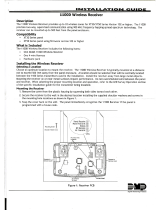
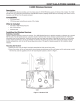
WIRE THE 1100D
1. Connect the red, yellow, green, and black
wires to the PANEL terminal on the 1100D
and connect the other ends to the 7, 8, 9,
and 10 terminals on the panel. See Figure 2.
2. Replace the cover back on to the base. The
panel immediately recognizes the 1100D if
the panel is programmed with a house code.
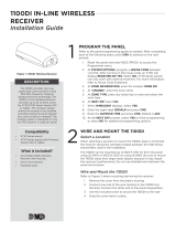
1100D WIRELESS RECEIVER
Installation Guide

1100D Installation Guide | Digital Monitoring Products, Inc 2
ADDITIONAL INFORMATION
Black
Green
Yellow
Red
J4
RED
PRO
J8
XT30/XT50 Series Panel
J7
RJ SUP
AC
1
2
3
4 5 6 7
8
10
11 12
9
+B
BELL
GND
SMK
RED
YEL
GRN
BLK
AC
-B
Can be extended
up to 500 feet
from the panel
using 22 AWG
1100D
Receiver
Figure 2: Wiring the 1100D to the Panel
1100D LED Operation
The six labeled LEDs on the 1100D PCB
display wireless receiver operation and
activity. See Figure 2 for LED locations
and Table 1 for LED indications.
House Code Explained
The house code identifies the panel,
receiver, and transmitters to each
other. The 1100D automatically sends
the specified house code to wireless
transmitters when transmitter serial
numbers are programmed in to the
panel. The 1100D only listens for
transmissions using the specified house
code or the programmed transmitters’
serial numbers.
LED Survey Operation for 1100 Series Transmitters
1100 Series transmitters provide a survey operation that allows one person to confirm that each
transmitter is communicating with the wireless receiver or panel to easily determine the best location
for the transmitters and the wireless receiver. Follow the directions below to test communication of
the wireless transmitters:
1. Remove the transmitter’s cover.
2. Hold the transmitter in the exact desired location.
3. Press the tamper switch to send data to the wireless receiver and determine if
communication is confirmed or faulty.
Confirmed: If communication is confirmed, the survey LED turns on when data is sent
to the wireless receiver and o when acknowledgment is received.
Faulty: If communication is faulty, the LED remains on for several seconds or flashes
multiple times in quick succession. Relocate the transmitter or the wireless receiver until
the LED confirms clear communication. Proper communication between the transmitter
and wireless receiver is verified when for each press or release of the tamper switch,
the transmitter’s LED blinks immediately on and immediately o.
LED INDICATIONS
RF RX Flashing yellow indicates data is being received from
a transmitter.
RF TX Flashing green indicates data is being sent to a
transmitter.
PANEL RX Flashing yellow indicates data is being received from
a panel.
PANEL TX Flashing green indicates data is being sent to the
panel.
STATUS Solid red indicates memory is being uploaded. Turns
o when complete.
PWR Solid green indicates there is power to the wireless
receiver.
Table 1: LED Indications

3 1100D Installation Guide | Digital Monitoring Products, Inc.
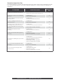
Transmitter Supervision Time
For listed installations, program the transmitter supervision time in panel zone programming as listed
in the following table. Refer to the panel programming guide for complete wireless programming
information.
UL Standard Listed Accessories
Supervision
Time
UL 268 Smoke-Automatic Fire Detectors
• 1100R Repeater
• 1164 Wireless Synchronized Smoke Detector
3
UL 365 Police Station Connected Burglar
Accessory
• 1100R Repeater
• 1103 Universal Transmitter
60
UL 521 Heat Detectors for Fire Protective
Signaling Systems
• 1100R Repeater
• 1183-135F, 1183-1353R Heat Detector
3
UL 609 Local Burglar Alarm Units and
System Accessory
• 1100R Repeater
• 1103 Universal Transmitter
60
UL 634 Connections and Switches for use
with Burglar Alarm Systems Accessory
• 1100R Repeater
• 1101, 1102, 1103, 1106 Universal Transmitters
60
UL 636 Holdup Alarm Units and Systems
Accessory
• 1142 Two-Button Holdup Transmitter 60
UL 639 Intrusion Detection Units
Accessory
• 1100R Repeater
• 1127W, 1127C PIR Motion Detectors
60
UL 985 Household Fire Warning System
Accessory
• 1100R Repeater
• 1135 Wireless Sounder
• 9060, 9063, 9862 Wireless Keypads
240
UL 1023 Household Burglary System Units
Accessory
• 1100R Repeater
• 1101, 1102, 1103, 1106 Universal Transmitters
• 1127W, 1127C PIR Motion Detectors
• 1135 Wireless Sounder
• 1142 Two-Button Holdup Transmitter
• 9060, 9063, 9862 Wireless Keypads
60
UL 1076 Proprietary Burglar Alarm Units
Accessory
• 1100R Repeater
• 1103 Universal Transmitter
60
UL 1610 Central Station Burglar Alarm
Units Accessory
• 1100R Repeater
• 1103 Universal Transmitter
• 1135 Wireless Sounder
• 9060, 9063, 9862 Wireless Keypads
60
Table 3: Wireless Transmitter Supervision TImes

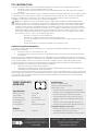
Designed, engineered, and
manufactured in Springfield, Missouri
using U.S. and global components.
INTRUSION • FIRE • ACCESS • NETWORKS
2500 North Partnership Boulevard
Springfield, Missouri 65803-8877
888.436.7832 | DMP.com
© 2018 Digital Monitoring Products, Inc.
LT-1820 18342
Specifications
Operating Voltage 8 to 14 VDC
Current Draw 40 mA
Frequency Range 905-924 MHz
Housing Dimensions 5.5" W x 3.75" L x 1" H
Housing Color White
Housing Material Flame Retardant ABS
Patents
U.S Patent Number 7, 239, 236
Certifications
FCC Part 15: CCKPC0114R6
Industry Canada: 5251A-PC0114R6
Intertek (ETL) Listed
• ANSI/UL 365 Police Station Connected Burglar
• ANSI/UL 609 Local Burglar Alarm Units & Systems
• ANSI/UL 636 Holdup Alarm Units & Systems
• ANSI/UL 985 Household Fire Warning Systems
• ANSI/UL 1023 Household Burglar Alarm System
Units
• ANSI/UL 1076 Proprietary Burglar Alarm Units
• ANSI/UL 1610 Central Station Burglar Alarm Units
Compatible With Devices Listed for:
• ANSI/UL 634 Connections and Switches for use
with Burglar Alarm Systems Accessory
• ANSI/UL 639 Intrusion Detections Units Accessory
FCC INFORMATION
This device complies with Part 15 of the FCC Rules. Operation is subject to the following two conditions:
1. This device may not cause harmful interference, and
2. this device must accept any interference received, including interference that may cause undesired
operation.
The antenna used for this transmitter must be installed to provide a separation distance of at least 20 cm (7.874
in.) from all persons. It must not be located or operated in conjunction with any other antenna or transmitter.
Changes or modifications made by the user and not expressly approved by the party responsible for
compliance could void the user’s authority to operate the equipment.
Note: This equipment has been tested and found to comply with the limits for a Class B digital device,
pursuant to part 15 of the FCC Rules. These limits are designed to provide reasonable protection against
harmful interference in a residential installation. This equipment generates, uses and can radiate radio
frequency energy and, if not installed and used in accordance with the instructions, may cause harmful
interference to radio communications. However, there is no guarantee that interference will not occur in a
particular installation. If this equipment does cause harmful interference to radio or television reception,
which can be determined by turning the equipment o and on, the user is encouraged to try to correct
the interference by one or more of the following measures:
• Reorient or relocate the receiving antenna.
• Increase the separation between the equipment and receiver.
• Connect the equipment into an outlet on a circuit dierent from that to which the receiver is
connected.
• Consult the dealer or an experienced radio/TV technician for help.
Industry Canada Information
This device complies with Industry Canada Licence-exempt RSS standard(s). Operation is subject to the
following two conditions:
1. This device may not cause interference, and
2. this device must accept any interference, including interference that may cause undesired operation
of the device.
This system has been evaluated for RF Exposure per RSS-102 and is in compliance with the limits specified by
Health Canada Safety Code 6. The system must be installed at a minimum separation distance from the antenna
to a general bystander of 7.87 inches (20 cm) to maintain compliance with the General Population limits.
Le présent appareil est conforme aux CNR d’Industrie Canada applicables aux appareils radio exempts de
licence. L’exploitation est autorisée aux deux conditions suivantes:
1. l’appareil ne doit pas produire de brouillage, et
2. l’utilisateur de l’appareil doit accepter tout brouillage radioélectrique subi, même si le brouillage est
susceptible d’en compromettre le fonctionnement.
L’exposition aux radiofréquences de ce système a été évaluée selon la norme RSS-102 et est jugée conforme aux
limites établies par le Code de sécurité 6 de Santé Canada. Le système doit être installé à une distance minimale
de 7.87 pouces (20 cm) séparant l’antenne d’une personne présente en conformité avec les limites permises
d’exposition du grand public.
1100D WIRELESS
RECEIVER
-
 1
1
-
 2
2
-
 3
3
-
 4
4


DMP Electronics 1100d Installation guide
- Category
- Security access control systems
- Type
- Installation guide
Ask a question and I''ll find the answer in the document
Finding information in a document is now easier with AI
in other languages
Related papers
-
 DMP Electronics 1100d Installation guide
-
 DMP Electronics 1100d Installation guide
-
 DMP Electronics 1100d Installation guide
-
 DMP Electronics 1100DI Installation guide
-
DMP Electronics 1127W PIR Motion Detector Installation guide
-
 DMP Electronics 1100DH Installation guide
-
 DMP Electronics 1100DH Installation guide
-
 DMP Electronics XT50 Series Installation guide
-
 DMP Electronics 1100XHE Installation guide
-
 DMP Electronics 1100DH Series Installation guide


Other documents
-
 Digital Monitoring Products 1100 D User guide
-
Digital Monitoring Products 1100DI In-Line Wireless Receiver Installation guide
-
 Digital Monitoring Products 1102 Universal Transmitter Installation guide
-
 Digital Monitoring Products XT30/XT50 Series Installation & Programming Guides
-
 Digital Monitoring Products 1183-135F Wireless Heat Detector Installation guide
-
 Digital Monitoring Products 1127 Wall Mount PIR Installation guide
-
 Digital Monitoring Products 1100D/DH Wireless Receiver Installation guide
-
 DMP 1100DH Series High Power Wireless Receivers Installation guide
-
 Digital Monitoring Products 1106 Universal Transmitter Installation guide
-
 Digital Monitoring Products 277 Trouble Annunciator Installation guide


