Page is loading ...

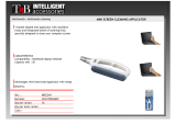
OPERATION MANUAL
EQUIPMENT
Hysol 175
®
P/N 98035
Loctite is a trademark of Loctite Corporation, U.S.A. Data in the manual is subject to change without notice.
Copyright 2001. Loctite Corporation. All rights reserved. 985132 06/01
Loctite Brazil
Av. Prof. Vernon Krieble, 91
06690-11-Itapevi
São Paulo-Brazil
Loctite America
s
1001 Trout Brook Crossing
Rocky Hill, CT 06067-3910
Loctite Canada Inc.
2225 Meadowpine Boulevard
Mississauga, Ontario L5N 7P2
Loctite Company de México, S.A.d e C.V.
Calzada de la Viga s/n, Fracc. Los Laureles
Loc. Tulpetlac, C.P. 55090
Ecatepac de Morelos, Edo. de México,
México
www.loctite.com
A Company

Page 1
Contents
1. Please Observe the Following..................................................................................2
1.1. Safety .........................................................................................................................2
1.2. Items supplied.............................................................................................................2
2. Description................................................................................................................2
3. Technical Data ..........................................................................................................2
4. Installation.................................................................................................................3
5. Operation...................................................................................................................3
5.1. The Auto Standby Feature ..........................................................................................4
5.2. Temperature adjustment .............................................................................................4
6. Application Hints ......................................................................................................4
7. Troubleshooting........................................................................................................5
7.1. Snubber Adjustment ...................................................................................................5
7.2. Feed mechanism adjustment .....................................................................................5
8. Care and Maintenance ..............................................................................................6
9. Accessories and Spare Parts ...................................................................................6
10. Warranty....................................................................................................................7
11. Appendix ...................................................................................................................8
12. Exploded Diagram. ...................................................................................................9
13. Parts List.................................................................................................................10

Page 2
1. Please Observe the Following
1.1. Safety
Do not touch the nozzle or molten adhesive with bare skin as they are hot - the
operating temperature of the Loctite
®
Hysol
®
175 is approximately 400ºF
(200ºC). Protective gloves should always be worn. Careless handling can
cause skin burns. If molten adhesive comes into contact with the skin immerse the
affected area immediately in plenty of cold water. Seek medical advice if necessary.
In addition to the safety instructions herein, any statutory regulations, local fire
insurance regulations, or other generally valid “regulations for accident prevention”
must be complied with when using this tool.
• Never use the tool if it is damaged in any way.
• Do not use this tool in damp rooms, outdoors while it is raining, or where there is
high humidity.
• Do not use this tool in the vicinity of any heat-sensitive materials, or any
flammable materials, liquids, or gases.
• Only use extension cables that meet the specification shown in “Technical data”.
• Never pull on the tool’s connecting cable.
1.2. Items supplied
Hot Melt Stick Dispenser
Plastic Stand
Manual
Plug-in Module 215°C
2. Description
The Loctite
®
Hysol
®
175 Hotmelt Applicator contains a powerful 400W stainless steel
cartridge heater which, in conjunction with it’s adjustable solid-state electronic
controller, provides both a fast 5-minute warm-up, and accuracy in temperature
control to within +/- 10°F (5°C) of the set temperature. Temperature adjustment is
achieved by changing the plug-in module – the operator simply chooses the most
appropriate module for the adhesive formulation to be used.
The advanced electronic controller provides an Auto Standby feature, allowing the
tool to be left on for long periods of time without the adhesive overheating (however
care should still be taken with soft formulations). If left unused for a while the tool will,
after a variable time (depending on the ambient temperature), switch to its power-
saving standby-mode, reducing the temperature of the tool to approximately 160°F
(72°C); it will return to its full operating temperature when operated.
Designed to comply with worldwide safety standards, the Loctite
®
Hysol
®
175 also
features a totally enclosed heater housing, and is fitted with thermal fuse protection.
3. Technical Data
Dimensions (L x H x W): approx. 12 1/4” x 9 5/8” x 2 11/16”
(approx. 312 x 245 x 70 mm)
Total weight: approx. 2.5 lbs. (1.15Kg)
Connection cable with main plug: 10 ft (3 m) long
Operating voltage: 110-120 VAC 50/60Hz
Power consumption 400W
Heating up time: 5 - 7 minutes
Operating temperature: approx. 392°F (200°C)
(dependent on Plug-in Module used)
Diameter of adhesive inlet: 1 11/16” (43 mm)
Extension cable: max. 65ft (20 m) long
Wire cross section: at least 16 a.w.g. (1.5 mm
2
)

Page 3
4. Installation
Before using the tool for the first time check it carefully for signs of external damage.
If any shipping damage is found DO NOT USE THE TOOL - return it to your supplier
immediately.
Steps 1 – 5 should be followed before connection to the main supply:
1. Locate the enclosed stand into the grooves at the base of the handle.
2. Check that the Plug-In Module is the appropriate one for the adhesive to be
used (refer to the Spares and Accessory lists at the end of this manual).
3. Pull handle back fully.
4. Drop adhesive cartridge into the breach of the tool and push fully forward.
5. Advance handle/plunger to rear of the adhesive cartridge by operating trigger.
6. Connect tool to main supply.
7. Red ‘Power On’ indicator light illuminates.
8. Allow tool to warm up for 5 minutes. Do not attempt to operate the tool until
this time has elapsed.
9. Operate trigger to push the adhesive cartridge forward to the reloading point.
10. Pull handle back fully and load a second adhesive cartridge. Operate trigger
to advance handle/plunger.
With a new tool it will be necessary to operate the trigger several times before
adhesive can be extruded; this is because air trapped in the heater housing first
needs to be evacuated.
5. Operation
Normal use:
• Fit the stand and place the tool in an upright position on a flat surface.
• Plug the tool into the power supply socket, and switch on the power.
• Wait 5 minutes for the tool to reach its normal operating temperature.
• Squeeze the trigger to advance the handle/plunger and extrude molten adhesive
through the nozzle.
• To stop extruding adhesive simply release the trigger.
During use, the plunger will advance through the breach area of the barrel as the
trigger is pulled. A point will be reached where the plunger no longer advances, but
just moves back and forth. When this occurs the tool needs reloading with another
adhesive cartridge.
• Pull the handle back fully.
• Insert a new adhesive cartridge.
• Operate the tool normally.
PLUG-IN MODULE
ADHESIVE CARTRIDGES

Page 4
5.1. The Auto Standby Feature
With a tool as powerful as the Loctite
®
Hysol
®
175 there would be a risk of adhesive
‘meltdown’ if it were left unused for too long at its normal operating temperature. To
avoid this a special standby function is built into the temperature controller, lowering
the temperature of the tool automatically after a period of inactivity. It should be
noted, however, that this function is not time-dependent, but temperature-dependent
i.e. the standby will activate at a point dependent on the ambient temperature and on
the temperature of the tool itself. A yellow light will illuminate when the standby
feature is active and the tool begins to cool down. If left long enough the tool’s
temperature will drop to approximately 270°F (130°C) and stabilize.
When the trigger is pulled to use the tool again the yellow light will extinguish, and the
tool will begin to heat up to it’s normal operating temperature (IT MAY TAKE
SEVERAL TRIGGER PULLS BEFORE THE LIGHT REMAIN EXTINGUISHED
AFTER THE TRIGGER IS RELEASED). The adhesive may appear very viscous at
this point, but will quickly thin as the temperature returns to normal.
When the tool is used for normal high output applications it is unlikely that the
standby feature will operate.
5.2. Temperature adjustment
Temperature adjustment of the tool is achieved using a range of electronic Plug-In
Modules with pre-set values. Simply select the required value (check that the Plug-In
Module is the appropriate one for the adhesive to be used, referring to the Spares
and Accessory lists at the end of this manual) and insert the module into the socket
on top of the tool.
6. Application Hints
As with all adhesives, performance depends on conditions of use. Suggestions or
recommendations contained herein are for guidance only, since actual conditions of
use are outside the supplier’s control.
• Ensure that the surfaces to be bonded are dry, free from dust, grease, and
loose particles.
• Apply adhesive to one surface only. Bring the two surfaces together
immediately, quickly making any further adjustments. Hold the joint for 20 -
30 seconds to complete the bond.
• When gluing dissimilar materials, apply the adhesive to the least heat
conductive of the two.
• On materials that are cold to the touch, a better bond can be made by pre-
warming them before applying adhesive.
• Surplus adhesive can be trimmed using a sharp knife once it has cooled.
Should molten adhesive drip onto a smooth or polished surface, allow it to
cool completely before removal.
• Spots or blobs of adhesive are recommended for work pieces having a large
surface area, or which are particularly long.
• Applying the adhesive in wavy lines is recommended for gluing textiles or
similar materials.
• Foam materials, like polystyrene, can be easily bonded to other surfaces.
However the adhesive must be applied to the other surfaces, not to the foam.
• Use only genuine Loctite
®
Hysol
®
adhesives to ensure reliable performance.
Loctite
®
Hysol
®
adhesives are non-toxic and non-flammable.

Page 5
7. Troubleshooting
Before proceeding with any repair or maintenance operation disconnect the
tool from the main electricity supply.
If the adhesive cartridge does not advance when the trigger is pulled, check that the
tool is plugged into the main supply, switched on, and has had sufficient time to warm
up. Otherwise carry out the ‘Snubber Adjustment’ as follows:
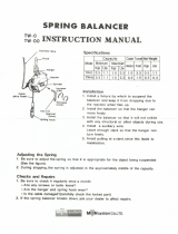
7.1. Snubber Adjustment
THIS IS FACTORY-SET BUT MAY REQUIRE MINOR ADJUSTMENT AFTER AN
INITIAL BEDDING-IN PERIOD
The snubber is a spring-loaded friction pad, which rubs on the side of the feed bar,
preventing its backward movement when the trigger is released. With the snubber
correctly adjusted, the plunger should remain stationary when the trigger is released.
If there is a backward movement, more snubber pressure is required. To increase
pressure turn the adjustment screw clockwise using a 3mm hexagon key. Turn a
quarter-turn each time and test. SEE DIAGRAM BELOW.
Do not over tighten as this will make plunger retraction difficult and cause premature
wear on the snubber pad.
7.2. Feed mechanism adjustment
THIS IS FACTORY SET AND SHOULD NOT REQUIRE ADJUSTMENT UNTIL THE
TOOL HAS BEEN IN USE FOR SOME TIME.
This adjustment compensates for any wear or slackness in the trigger movement.
Typically free play at the trigger tip should be 0.3 – 0.4” (8 - 10mm).
To re-set, insert a 2.5mm hexagon key through the upper hole in feed bar handle and
turn clockwise to decrease free play. SEE DIAGRAM ABOVE.
If feed mechanism adjustment is set too tight plunger withdrawal will be very difficult.
FOR ANY REPAIRS OR ADJUSTMENTS – OTHER THAN THOSE DETAILED IN
THIS MANUAL – PLEASE CONTACT 1-800-LOCTITE.
SNUBBER ADJUSTMENT
(3mm HEXAGON KEY)
FEED MECH. ADJUSTMENT
(2.5mm HEXAGON KEY)
RETRAC
T
HANDLE
FULLY
FREE PLAY
0.3
–
0.4”

Page 6
8. Care and Maintenance
• When in use, do not lay the tool on its side - always place upright using the stand
provided.
• Do not use excessive force on the trigger. Ensure that the tool has fully warmed
up before use.
• Keep the nozzle clean to prevent adhesive build-up. This is easily done by wiping
the nozzle with clean paper or cloth while the nozzle is still warm.
Replace the nozzle if worn or damaged. Only replace the nozzle while the tool is
still warm. Disconnect the tool from the power supply before proceeding, and
always use protective gloves.
Unscrew the nozzle from the tool using either a 1/2” (13 mm) spanner, or the
spanner-feature moulded into the dispenser stand. Fit the replacement nozzle,
ensuring that it is securely tightened.
9. Accessories and Spare Parts
Spare Parts Part Number
2-Part Nozzle Assembly - supplied with tool 985078
Nozzle Adapter 985088
Trigger 985148
Temperature Control 110/120V 985162
Heater Assembly 120V 400W 985144
Main Capacitor Assembly 985178
Dispenser Stand 985133
Nozzle Shroud Kit – Qty 5 985223
Feed Bar Assembly 985154
Handle Kit 985224
Qty 2 – Moulded Handles, Item 1
Qty 9 – Casing Screws, Item 43
Feed Bar Kit 985220
Qty 1 – Feed Bar Handle, Item 23
Qty 1 – Feed Bar Handle Screw, Item 45
Qty 1 – Feed Mechanism Toggle, Item 21
Qty 1 – Snubber Assy., Item 15
Qty 1 – Screw, Snubber, Item 48
Heater Housing Kit 985221
Qty 1 – O-ring, Heater Housing, Item 7
Qty 1 – Heater Housing, Item 8
Qty 1 – Earth (Ground) Screw, Item 47
Qty 1 – Helical Spring Lock Washer, Item 49
Barrel Kit 985222
Qty 1 – Rear Barrel, Item 2
Qty 1 – PTFE Front Barrel, Item 3
U.S. Cordset Kit 985226
Qty 1 – Cordset, Item 17
Qty 1 – Cord Clamp, Item 16
Qty 2 – Screws, Item 42
Plug-In Module
Plug-In Module 383°F (195°C) 985164
(Recommended for standard EVA-based hotmelt adhesives)
Plug-In Module 419° F (215° C) 985134
(Recommended fro use with polyamides adhesives only)

Page 7
Accessories Part Number
Nozzle 1-Hole Kit, Qty 5, 0.080” (2 mm) orifice 985225
Nozzle 2-Hole 985110
Nozzle 3-Hole 985111
Extension Nozzle 0.120” (3 mm) 985112
Needle Extension Nozzle 0.050” (1.3 mm) 985113
Spreader Extension Nozzle 0.250” (6 mm) 985114
‘L’ Nozzle, overlap carton sealing 985115
‘T’ Nozzle, center flap carton sealing 985116
(Note: the nozzle shroud cannot be re-fitted with some optional nozzles)
Tool Hanger / Balancer 985243
Heavy-Duty Free-Standing Metal Stand 985087
10. Warranty
This applicator is guaranteed against faulty workmanship, materials and malfunction
for a period of 12 months from the date of purchase. This guarantee does not apply:
1. If the applicator has been dropped, damaged due to careless handling, or has
not been used in accordance with the manufacturer’s instructions.
2. If the applicator has been modified in any way.
3. If the applicator has been opened, or the electrical cable has been damaged or
replaced.
4. If adhesive other than formulations supplied by the manufacturer of the
applicator have been used.
The manufacturer undertakes to repair or replace at their discretion. The tool will be
returned to the distributor or user freight prepaid.
Sellers and Manufacturer’s only obligation shall be to replace such quantity of the
product proved to be defective. Neither seller nor manufacturer shall be liable for any
injury, loss or damage, direct or consequential, arising out of the use, or the inability
to use, the product. User shall determine the suitability of the product for his intended
use and the user assumes all risks and liability whatsoever in connection therewith.

Page 8
11. Appendix
Pictures of available nozzles/accessories.
985087
HEAVY DUTY FREE-STANDING
METAL STAND
985243
TOOL HANGER / BALANCER
985110
2 HOLE
985111
3 HOLE
985112
EXTENSION
985113
NEEDLE
985114
SPREADER
985115
‘L’ NOZZLE
985225
1 HOLE
985116
‘T’ NOZZLE
985088
NOZZLE ADAPTOR

Page 9
12. Exploded Diagram.

Page 10
13. Parts List.
51 1 MAIN CAPACITOR ASSEMBLY 985178
50 1 TORSION SPRING
49 1 HELICAL SPRING LOCK WASHER HEATER HOUSING KIT 985221
48 1 SNUBBER SCREW FEED BAR KIT 985220
47 1 EARTH (GROUND) SCREW HEATER HOUSING KIT 985221
46 1 FEED BAR PLUNGER SCREW
45 1 FEED BAR HANDLE SCREW FEED BAR KIT 985220
44 1 FEED MECHANISM ADJUSTER SCREW
43 9 CASING SCREW HANDLE KIT 985224
42 2 SCREW US CORD SET KIT 985226
41 1 EARTH (GROUND) WIRE ASSEMBLY
40 1 RETAINER RING
39 1 RETAINER RING
38 1 TRIGGER PIVOT PIN
37 1 PIVOT PIN TRIGGER LINK
36 1 UPPER TOGGLE PIN
35 1 LOWER TOGGLE PIN
34 1 PLUG-IN MODULE 195°C 985164
33 1 MODULE CARRIER
32 1 TEMPERATURE CONTROL, 110/120 VOLT 985162
31 1 PLUNGER
30 1 FRONT FEED BAR BUSHING
29 1 FEED MECHANISM SPRING
28 1 PRESSURE PLATE
27 1 SPACER GUARD
26 1 FEED MECHANISM CARRIER
25 1 FEED MECHANISM ASSEMBLY
24 1 FEED BAR ASSEMBLY 985154
23 1 FEED BAR HANDLE FEED BAR KIT 985220
22 1 REAR FEED BAR BUSHING
21 1 TOGGLE FEED BAR KIT 985220
20 1 RIGHT TRIGGER LINK
19 1 LEFT TRIGGER LINK
18 1 TRIGGER 985148
17 1 U.S. CORDSET ASSEMBLY US CORD SET KIT 985226
16 1 CORD CLAMP US CORD SET KIT 985226
15 1 SNUBBER ASSEMBLY FEED BAR KIT 985220
14 1 HANDLE GRIP
13 1 DISPENSER STAND 985133
12 1 HEATER ASSEMBLY. 120 VOLT, 400 WATT 985144
11 1 NOZZLE BODY ASSEMBLY 985078
10 1 NOZZLE SHROUD
NOZZLE SHROUD KIT, QTY 5
985223
9 1 HEATER HOUSING SPACER
8 1 HEATER HOUSING HEATER HOUSING KIT 985221
7 1 HEATER HOUSING 0-RING HEATER HOUSING KIT 985221
6 1 LOCK RING, ALUMINIUM
5 1 PTC SENSOR ASSEMBLY
4 1 BARREL SUPPORT
3 1 PTFE SUPPORT BARREL KIT 985222
2 1 REAR BARREL BARREL KIT 985222
1 1 HANDLES, PAIR HANDLE KIT 985224
ITEM QTY. DESCRIPTION REBUILD KITS AVAILABLE PART NO.
PARTS LIST
/