Falcon 900 User manual

Type
User manual
Allegion
Connect
Technical Manual
This manual covers the Allegion Connect products in multiple brands.
See the table of contents to locate the desired brand information.
ii • Allegion Connect • Technical Manual Allegion Connect • Technical Manual • 2
Contents
3 Overview
3 Wiring Harnesses
4 Von Duprin Products
4 Electric Power Transfer: EPT-10
4 RX/LX/RX-LX Exit Device
5 QEL Exit Device
5 QEL/(RX/LX/RX-LX) Exit Device
6 EL Exit Device
6 EL/(RX/LX/RX-LX) Exit Device
7 CX (Chexit) Motor-Driven Exit Device
8 ALK Exit Device
8 E7500 Mortise Lock
9 SS7500 Mortise Lock
9 E996/M996 Trim
10 6100/6200 Series Electric Strikes
11 Falcon Products
11 RX Exit Device
12 MEL Exit Device
12 MEL/RX Exit Device
13 EL Exit Device
13 EL/RX Exit Device
14 EA (Exit Alarm) Exit Device
15 T-Series Electrified Locks (T851/T881)
15 T851/T881 (12 VDC)
16 T851/T881 (24 VDC)
17 MA-Series Electrified Locks (MA851/MA881)
17 MA851/MA881 (12 and 24 VDC)
18 Schlage Products
18 L Series Locks (8-pin connector)
19 L Series Locks (8-pin + 4-pin connector)
20 ND Series Locks
21 Ives Products
21 3CB1/5BB1 TW/TWM Architectural Hinge
22 700-TW8/700CS-TWP Continuous Hinge
23 112XY/224XY-TWP Continuous Hinge
24 Intermediate and Pocket Pivots
25 Connector Kit
26 Extraction Tool
Von Duprin Products
Allegion Connect • Technical Manual • 3
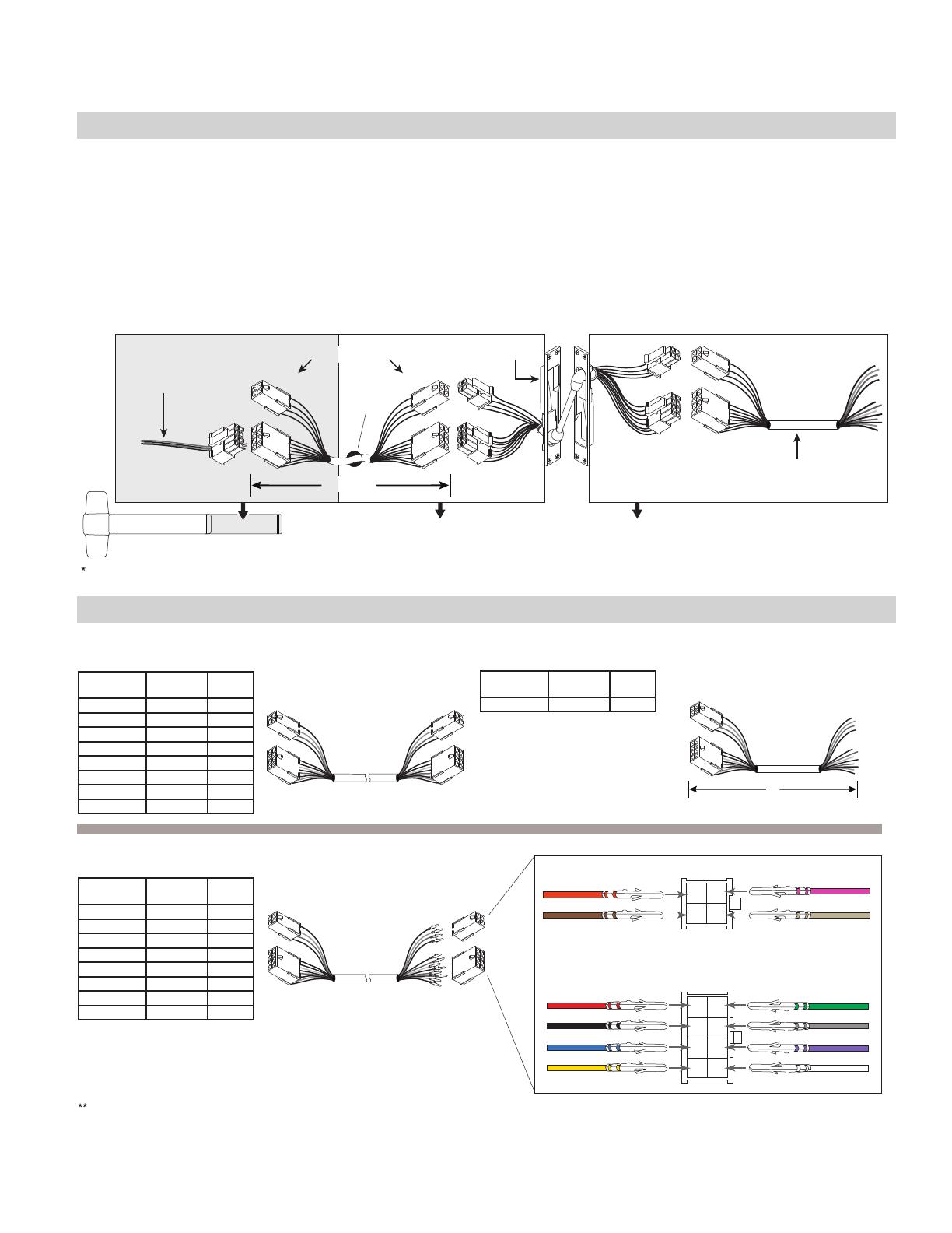
Overview
Electrified Hardware
EPT or Hinge
Variable Length Wiring Harnesses
Standard wiring hole may need to be enlarged slightly to fit connector through door surface.
The 20 gauge wiring harnesses have Allegion Connect 8 pin and 4 pin connectors on each end, or can be ordered with the connectors on one end only. One
wiring assembly is used to connect the electrified hardware to the EPT/hinge, and a 6” CON-6W wiring harness can be used to route from the EPT/hinge to
field wiring.
The EPT or electrified hinge is supplied with Allegion Connect 8 pin and 4 pin connectors, or 8 pin connector only. See related product page.
The electrified exit device, lock, trim, or strike is supplied with the Allegion Connect 8 pin and/or 4 pin connectors. In some cases an adapter is
supplied and is shown in greater detail on the application pages of this manual. There are limitations regarding what Allegion Connect products can
be combined. Consult factory for combinations not shown in this manual.
EPT-CON
wire hole
in door
Variable Length Wiring Harness
inside device in door in frame
6" to 192"
Electrified Exit
Device, Trim,
Strike, or Lock
**
CON-6W 6" Wiring Harness
(for connection to field wiring)
*
Wiring Harnesses
Variable Length Harness
with connectors on both ends
(for use with Hollow Metal Doors)
6”
8 Pin
Back of Connectors
8
White
7
Violet
6
Gray
5 Green
1 Red
2 Black
3 Blue
4 Yellow
1
2
3
4
5
6
7
8
2 Brown
1 Orange
4 Tan
3 Pink
1
2
3
4
4 Pin
Stripped leads of CON-6W connect to field wiring. Field wiring from frame to power supply must be appropriate gauge (Variable Length Harnesses
have 20 gauge wire and are not acceptable). Refer to wire gauge specifications in instructions for the particular electrified hardware.
6
12
26
32
38
44
50
192
106190
106191
106192
106193
106194
106195
106196
106197
CON-6
CON-12
CON-26
CON-32
CON-38
CON-44
CON-50
CON-192
INTERNAL
PART #
PART # TOTAL
LENGTH
6
12
26
32
38
44
50
192
106201
106202
106203
106204
106205
106206
106207
106208
CON-6P
CON-12P
CON-26P
CON-32P
CON-38P
CON-44P
CON-50P
CON-192P
INTERNAL
PART #
PART # TOTAL
LENGTH
6106210 CON-6W
INTERNAL
PART #
PART # TOTAL
LENGTH
For use in tight fit applications such as routing through conduit or
through a door.
6" Harness
6" with connectors on one end only
(for connection to field wiring)
**
Variable Length Harness
with connectors on one end, crimped
pins and loose connectors on other end
(for use with Wood Doors)
Von Duprin Products
4 • Allegion Connect • Technical Manual
Von Duprin Products
Electric Power Transfer: EPT-10
See page 3 for system overview and wiring harness usage.
6" to 192"
CON-6W 6" Wiring Harness
(for connection to field wiring)
EPT-CONVariable Length
Wiring Harness
Electrified Exit Device, Trim, Strike, or Lock
A
B
C
A B C
WIRE
COLOR
PIN PIN EPT
WIRE
COLORS
PIN WIRE
COLOR
Orange 1
1 Orange
1 Orange
Brown 2
2 Brown
2 Brown
Pink 3
3
3 Pink
Tan 4
4
4 Tan
Red 1
1 Red
1 Red
Black 2
2 Black
2 Black
Blue 3
3 Blue
3 Blue
Yellow 4
4 Yellow
4 Yellow
Green 5
5 Green
5 Green
Gray 6
6 Gray
6 Gray
Violet 7
7 Violet
7 Violet
White 8
8 White
8 White
NOTE: Field wiring from frame to power supply must be appropriate gauge. Refer to wire gauge specifications in instructions
for the particular hardware.
RX/LX/RX-LX Exit Device
See page 3 for system overview and wiring harness usage. Colors shown below at wiring harness should remain consistent
throughout the EPT or hinge and harness outside of frame.
FUNCTION WIRE COLOR PIN PIN WIRE COLOR
Not Used
1 1 Red
2 2 Black
RX/
RX-LC
Normally Open (NO) Blue 3
3 Blue
Normally Closed (NC) Yellow 4
4 Yellow
Common (C) Red or Green 5
5 Green
LX
LX-LC
Normally Open (NO) Gray 6
6 Gray
Normally Closed (NC) Violet 7
7 Violet
Common (C) White or Black 8
8 White
EPT-CON
wire hole
in door
Variable Length Wiring Harness
inside device in door in frame
not
used
RX / LX / RX-LX CON
A B
A
B
Von Duprin Products
Allegion Connect • Technical Manual • 5
QEL Exit Device
See page 3 for system overview and wiring harness usage. Colors shown below at wiring harness should remain consistent
throughout the EPT or hinge and harness outside of frame.
FUNCTION WIRE COLOR PIN PIN WIRE COLOR
QEL
Power Black 1
1 Red
Power Black 2
2 Black
Not Used
3 3 Blue
4 4 Yellow
5 5 Green
6 6 Gray
7 7 Violet
8 8 White
Motor and Motor Cable
are standard, non-CON
components.
*
EPT-CON
wire hole
in door
QEL Motor Cable with QEL CON Adapter Harness
040069
QEL CON
Adapter Harness
106198
(see chart below)
QEL
Motor Cable
114320
Variable Length Wiring Harness
**
inside device
in door in frame
not
used
QEL
Motor
BA
B
A
NOTE: The 6' cable (110388) that is furnished with standard QEL devices is not furnished or required for CON applications.
QEL/(RX/LX/RX-LX) Exit Device
See page 3 for system overview and wiring harness usage. Colors shown below at wiring harness should remain consistent
throughout the EPT or hinge and harness outside of frame.
FUNCTION WIRE COLOR PIN PIN WIRE COLOR
QEL
Power Black 1
1 Red
Power Black 2
2 Black
RX/
RX-LC
Normally Open (NO) Blue 3
3 Blue
Normally Closed (NC) Yellow 4
4 Yellow
Common (C) Red or Green 5
5 Green
LX/
LX-LC
Normally Open (NO) Gray 6
6 Gray
Normally Closed (NC) Violet 7
7 Violet
Common (C) White or Black 8
8 White
Motor and Motor Cable
are standard, non-CON
components.
Connector in 106198
not used since QEL
wires go directly to
switch connector.
**
*
EPT-CON
wire hole
in door
QEL CON
Adapter Harness
106198
(see chart below)
QEL
Motor Cable
114320
Variable Length Wiring Harness
*
*
inside device
in door in frame
not
used
QEL
Motor
**
not used
QEL Motor Cable with QEL CON
Adapter Harness
040069
RX / LX / RX-LX CON
B
A
A B
NOTE: The 6' cable (110388) that is furnished with standard QEL devices is not furnished or required for CON applications.
6 • Allegion Connect • Technical Manual
Von Duprin Products
EL Exit Device
See page 3 for system overview and wiring harness usage. Colors shown below at wiring harness should remain consistent
throughout the EPT or hinge and harness outside of frame.
FUNCTION WIRE COLOR PIN PIN WIRE COLOR
EL
Power Black 1
1 Red
Power Black 2
2 Black
Not Used
3 3 Blue
4 4 Yellow
5 5 Green
6 6 Gray
7 7 Violet
8 8 White
Solenoid and Pulse
Width Module are
standard, non-CON
components.
*
EPT-CON
wire hole
in door
EL CON
Adapter Harness
106198
(see chart below)
EL Pulse
Width Module
050534
EL Solenoid Variable Length Wiring Harness
*
*
inside device in door in frame
not
used
A
B
A B
NOTE: The 6' cable (110388) that is furnished with standard EL devices is not furnished or required for CON applications.
EL/(RX/LX/RX-LX) Exit Device
See page 3 for system overview and wiring harness usage. Colors shown below at wiring harness should remain consistent
throughout the EPT or hinge and harness outside of frame.
FUNCTION WIRE COLOR PIN PIN WIRE COLOR
EL
Power Black 1
1 Red
Power Black 2
2 Black
RX/
RX-LC
Normally Open (NO) Blue 3
3 Blue
Normally Closed (NC) Yellow 4
4 Yellow
Common (C) Red or Green 5
5 Green
LX/
LX-LC
Normally Open (NO) Gray 6
6 Gray
Normally Closed (NC) Violet 7
7 Violet
Common (C) White or Black 8
8 White
Solenoid and Pulse
Width Module are
standard, non-CON
components.
Connector in 106198
not used since solenoid
wires go directly to
switch connector.
**
*
EPT-CON
wire hole
in door
EL CON
Adapter Harness
106198
(see chart below)
EL Pulse
Width Module
050534
EL
Solenoid
Variable Length Wiring Harness
*
*
inside device in door in frame
not
used
RX / LX / RX-LX CON
not used
**
A
B
A B
NOTE: The 6' cable (110388) that is furnished with standard EL devices is not furnished or required for CON applications.
Von Duprin Products
Allegion Connect • Technical Manual • 7
CX (Chexit) Motor-Driven Exit Device
See page 3 for system overview and wiring harness usage. Colors shown below at wiring harness should remain consistent
throughout the EPT or hinge and harness outside of frame.
EPT-CON
wire hole
in door
Variable Length Wiring Harness
inside device in door in frame
OR
12 Pin
Connector to
CX Module
4+8 Pin
Connector
CX CON
Adapter
Harness
116724
CX
Module
CX Standard 4’ Harness
040191
A
B
B
A B
These parts are
provided when CX
is ordered with CON.
Variable Length
Wiring Harness
ordered separately.
040191 is included with Standard CX
(no CON included).
040191 is saleable. Can be connected
to EPT-CON without using Variable
Length Wiring Harness.
FUNCTION WIRE COLOR PIN PIN WIRE COLOR
Door Position Switch Input DPS Orange 1
1 Orange
Alarm Relay Output NO/NC Brown 2
2 Brown
Unused Wires Pink 3
3 Pink
Unused Wires Tan 4
4 Tan
Power Supply +24V Input 24VDC Red 1
1 Red
Power Supply Ground GND Black 2
2 Black
Alarm Relay Output COM Blue 3
3 Blue
Fire Alarm Input FA Yellow 4
4 Yellow
Inhibit Input INH Green 5
5 Green
Gang Input/Output GNG Gray 6
6 Gray
Secure Relay Output NO/NC Violet 7
7 Violet
Secure Relay Output COM White 8
8 White
8 • Allegion Connect • Technical Manual
Von Duprin Products
ALK Exit Device
See page 3 for system overview and wiring harness usage. Colors shown below at wiring harness should remain consistent
throughout the EPT or hinge and harness outside of frame.
EPT-CON
wire hole
in door
Variable Length Wiring Harness
inside device in door in frame
not
used
ALK
ALK CON
Adapter Harness
106182
+
24VDC
External Inhibit
(non-polarized)
FUNCTION WIRE COLOR PIN PIN WIRE COLOR
ALK
To Power Supply +24VDC Red 1
1 Red
Power Supply Ground Black 2
2 Black
External Inhibit Blue 3
3 Blue
External Inhibit Yellow 4
4 Yellow
Not Used
5 5 Green
6 6 Gray
7 7 Violet
8 8 White
A
B
A B
E7500 Mortise Lock
See page 3 for system overview and wiring harness usage. Colors shown below at wiring harness should remain consistent
throughout the EPT or hinge and harness outside of frame.
EPT-CONE7500 Solenoid CON
Adapter Harness
106198 (see chart below)
E7500 Variable Length Wiring Harness
in door in frame
not
used
not used
E7500 Switch CON Adapter Harness
106181
FUNCTION WIRE COLOR PIN PIN WIRE COLOR
E7500
Solenoid
Power Black 1
1 Red
Power Black 2
2 Black
S1- monitors
auxiliary bolt and
latch bolt
Normally Closed (NC) Yellow 3
3 Blue
Normally Open (NO) Blue 4
4 Yellow
Common (C) Red 5
5 Green
S2- monitors trim
inputs (locked or
unlocked)
Normally Closed (NC) Violet 6
6 Gray
Normally Open (NO) Gray 7
7 Violet
Common (C) White 8
8 White
Connector in
106198 not
used since
solenoid wires
go directly to
switch
connector.
*
*
A
B
A B
Von Duprin Products
Allegion Connect • Technical Manual • 9
SS7500 Mortise Lock
See page 3 for system overview and wiring harness usage. Colors shown below at wiring harness should remain consistent
throughout the EPT or hinge and harness outside of frame.
EPT-CONSS7500 Switch CON
Adapter Harness
106181
SS7500 Variable Length Wiring Harness
in door in frame
not
used
FUNCTION WIRE COLOR PIN PIN WIRE COLOR
Not Used
1 1 Red
2 2 Black
S1- monitors
auxiliary bolt and
latch bolt
Normally Closed (NC) Yellow 3
3 Blue
Normally Open (NO) Blue 4
4 Yellow
Common (C) Red 5
5 Green
S2- monitors trim
inputs (locked or
unlocked)
Normally Closed (NC) Violet 6
6 Gray
Normally Open (NO) Gray 7
7 Violet
Common (C) White 8
8 White
A
B
A B
E996/M996 Trim
See page 3 for system overview and wiring harness usage. Colors shown below at wiring harness should remain consistent
throughout the EPT or hinge and harness outside of frame.
EPT-CON
wire hole
in door
E996/M996 CON
Adapter Harness
106183
(see chart below)
E996/M996 Variable Length Wiring Harness
inside device in door in frame
not
used
FUNCTION WIRE COLOR PIN PIN WIRE COLOR
E996/M996
Power White 1
1 Red
Power Black 2
2 Black
Not Used
3 3 Blue
4 4 Yellow
5 5 Green
6 6 Gray
7 7 Violet
8 8 White
A
B
A B
NOTE: The Cable.10038 that is furnished with standard E996/M996 trim is not furnished or required for CON applications.
10 • Allegion Connect • Technical Manual
Von Duprin Products
6100/6200 Series Electric Strikes
See page 3 for system overview and wiring harness usage. Colors shown below at wiring harness should remain consistent
throughout the EPT or hinge and harness outside of frame.
FUNCTION WIRE COLOR PIN PIN WIRE COLOR
Solenoid
Not Used
Power Black 1
1 Red
Power Black 2
2 Black
3
3 Blue
4
4 Yellow
5
5 Green
6
6 Gray
7
7 Violet
8
8 White
*
6000 Strike Solenoid CON Adapter Harness
106187
(see chart below)
Standard
Strike
CON-6W 6" Wiring Harness
(for connection to field wiring)
not
used
6” harness is for single door application. For double door application, specify variable length harness to
connect electric strike to power transfer.
*
B
A
A B
FUNCTION WIRE COLOR PIN PIN WIRE COLOR
Fail
Secure
(FSE)
Solenoid
Power Black 1
1 Red
Power Black 2
2 Black
DS Models
Only
S1- monitors
tripper
Normally Closed (NC) Blue 3
3 Blue
Normally Open (NO) Yellow 4
4 Yellow
Common (C) Red 5
5 Green
S2- monitors
strike lip
Normally Closed (NC) Gray 6
6 Gray
Normally Open (NO) Violet 7
7 Violet
Common (C) White 8
8 White
FUNCTION WIRE COLOR PIN PIN WIRE COLOR
Fail
Safe
(FS)
Solenoid
Power Black 1
1 Red
Power Black 2
2 Black
DS Models
Only
S1- monitors
tripper
Normally Closed (NC) Blue 3
3 Blue
Normally Open (NO) Yellow 4
4 Yellow
Common (C) Red 5
5 Green
S2- monitors
strike lip
Normally Open (NO) Gray 6
6 Gray
Normally Closed (NC) Violet 7
7 Violet
Common (C) White 8
8 White
6” harness is for single door application. For double door application, specify variable length harness to
connect electric strike to power transfer.
Connector in 106198 not used since solenoid wires go directly to switch connector.
*
**
**
*
6000 Strike Solenoid CON
Adapter Harness
106198 (see chart below)
DS
(Double Switch)
Strike
CON-6W 6" Wiring Harness
(for connection to field wiring)
not
used
not used
6000 Strike Switch CON Adapter Harness
106181
A
B
A B
A B
Falcon Products
Allegion Connect • Technical Manual • 11
RX Exit Device
See page 3 for system overview and wiring harness usage. Colors shown below at wiring harness should remain consistent
throughout the EPT or hinge and harness outside of frame.
FUNCTION WIRE COLOR PIN PIN WIRE COLOR
1 1 Red
2 2 Black
RX
Normally Open (NO) Violet 3
3 Blue
Normally Closed (NC) Gray 4
4 Yellow
Common (C) Black 5
5 Green
6 6 Gray
7 7 Violet
8 8 White
EPT-CON
wire hole
in door
Variable Length Wiring Harness
in door in frame
not
used
RX CON
inside
device
A
B
A B
12 • Allegion Connect • Technical Manual
Falcon Products
MEL Exit Device
See page 3 for system overview and wiring harness usage. Colors shown below at wiring harness should remain consistent
throughout the EPT or hinge and harness outside of frame.
FUNCTION WIRE COLOR PIN PIN WIRE COLOR
MEL
Power Black 1
1 Red
Power Black 2
2 Black
Not Used
3 3 Blue
4 4 Yellow
5 5 Green
6 6 Gray
7 7 Violet
8 8 White
Motor and Motor Cable
are standard, non-CON
components.
*
EPT-CON
wire hole
in door
MEL Motor Cable with MEL CON
Adapter Harness
040069
MEL CON
Adapter Harness
106198
(see chart below)
MEL
Motor Cable
114320
Variable Length Wiring Harness
**
in door in frame
not
used
MEL
Motor
A
B
A B
inside
device
NOTE: The 6' cable (110388) that is furnished with standard EL devices is not furnished or required for CON applications.
MEL/RX Exit Device
See page 3 for system overview and wiring harness usage. Colors shown below at wiring harness should remain consistent
throughout the EPT or hinge and harness outside of frame.
Motor and Motor Cable
are standard, non-CON
components.
Connector in 106198
not used since MEL
wires go directly to
switch connector.
**
*
EPT-CON
wire hole
in door
MEL CON
Adapter Harness
106198
(see chart below)
MEL
Motor Cable
114320
Variable Length Wiring Harness
*
**
*
in door in frame
not
used
MEL
Motor
MEL Motor Cable with MEL CON
Adapter Harness
040069
RX CON
FUNCTION WIRE COLOR PIN PIN WIRE COLOR
MEL
Power Black 1
1 Red
Power Black 2
2 Black
RX
Normally Open (NO) Violet 3
3 Blue
Normally Closed (NC) Gray 4
4 Yellow
Common (C) Black 5
5 Green
Not
Used
6
6 Gray
7
7 Violet
8
8 White
inside
device
not used
A
B
A B
NOTE: The 6' cable (47269206) that is furnished with standard MEL devices is not furnished or required for CON
applications.
Falcon Products
Allegion Connect • Technical Manual • 13
EL Exit Device
See page 3 for system overview and wiring harness usage. Colors shown below at wiring harness should remain consistent
throughout the EPT or hinge and harness outside of frame.
FUNCTION WIRE COLOR PIN PIN WIRE COLOR
EL
Power Black 1
1 Red
Power Black 2
2 Black
Not Used
3 3 Blue
4 4 Yellow
5 5 Green
6 6 Gray
7 7 Violet
8 8 White
Solenoid and Pulse
Width Module are
standard, non-CON
components.
*
EPT-CON
wire hole
in door
EL 6” Adapter Cable
with
8 Pin Connector
106198
(see chart below)
EL Pulse
Width Module
050534
EL Solenoid Variable Length Wiring Harness
*
*
in door in frame
not
used
inside
device
A
B
A B
NOTE: The 6' cable (110388) that is furnished with standard EL devices is not furnished or required for CON applications.
EL/RX Exit Device
See page 3 for system overview and wiring harness usage. Colors shown below at wiring harness should remain consistent
throughout the EPT or hinge and harness outside of frame.
FUNCTION WIRE COLOR PIN PIN WIRE COLOR
EL
Power Black 1
1 Red
Power Black 2
2 Black
RX
Normally Open (NO) Violet 3
3 Blue
Normally Closed (NC) Gray 4
4 Yellow
Common (C) Black 5
5 Green
Not
Used
6
6 Gray
7
7 Violet
8
8 White
Solenoid and Pulse
Width Module are
standard, non-CON
components.
Connector in 106198
not used since EL wires
go directly to RX
connector.
**
*
inside
device
EPT-CON
wire hole
in door
EL 6" Adapter
Cable with
8 Pin Connector
106198
(see chart below)
EL Pulse
Width Module
050534
EL
Solenoid
Variable Length Wiring Harness
*
*
in door in frame
not
used
**
RX CON
not used
A
B
A B
NOTE: The 6' cable (110388) that is furnished with standard EL devices is not furnished or required for CON applications.
14 • Allegion Connect • Technical Manual
Falcon Products
EA (Exit Alarm) Exit Device
See page 3 for system overview and wiring harness usage. Colors shown below at wiring harness should remain consistent
throughout the EPT or hinge and harness outside of frame.
EPT-CON
wire hole
in door
Variable Length Wiring Harness
in door in frame
not
used
EA
EAK CON Adapter Harness
106182
+
24VDC
External Inhibit
(non-polarized)
inside
device
FUNCTION WIRE COLOR PIN PIN WIRE COLOR
EA
To Power Supply +24VDC Red 1
1 Red
Power Supply Ground Black 2
2 Black
External Inhibit Blue 3
3 Blue
External Inhibit Yellow 4
4 Yellow
Not Used
5 5 Green
6 6 Gray
7 7 Violet
8 8 White
A
B
A B
Falcon Products
Allegion Connect • Technical Manual • 15
Falcon Products
T-Series Electrified Locks (T851/T881)
Electrical Specifications:
Fail Safe/Fail Secure
.65 AMP @ 12 VDC
.32 AMP @ 24 VDC
T851 Storeroom Fail Safe:
Deadlocking latch bolt operated by lever from either side, except when outer lever is electrically locked. When outer lever is locked (inoperable), latch bolt
retracted by key in cylinder outside. Inside lever is always free.
T881 Storeroom Fail Secure:
Deadlocking latch bolt operated by lever inside at all times. Outside lever is inoperable until electrically unlocked, then latch bolt is operable from either
side. When outside lever is inoperable, latch bolt retracted by key in cylinder outside.
T851/T881 (12 VDC)
12 VDC Configuration Shown
12VDC
12 VDC Harness
(supplied)
must be used
T-Series
Lock
Variable Length
Wiring Harness
(6” to 192”)
EPT or Electrified Hinge
See chart below
for wire colors
A
B
Power Only - T851, T881
Lock
Connector
Harness
Connector
PURPOSE FUNCTION
WIRE
COLOR
PIN PIN WIRE
COLOR
EL / EU
Power Red 1
->
1 Red
Power Black 2
->
2 Black
Not Used
3 3 Blue
4 4 Yellow
5 5 Green
6 6 Gray
7 7 Violet
8 8 White
A B
16 • Allegion Connect • Technical Manual
Falcon Products
T851/T881 (24 VDC)
24 VDC Configuration Shown
24VDC
24 VDC Harness
(supplied)
must be used
T-Series
Lock
Variable Length
Wiring Harness
(6” to 192”)
EPT or Electrified Hinge
See chart below
for wire colors
A
B
Power Only - T851, T881
Lock
Connector
Harness
Connector
PURPOSE FUNCTION
WIRE
COLOR
PIN PIN WIRE
COLOR
EL / EU
Power Red 1
->
1 Red
Power Black 2
->
2 Black
Not Used
3 3 Blue
4 4 Yellow
5 5 Green
6 6 Gray
7 7 Violet
8 8 White
A B
Allegion Connect • Technical Manual • 17
MA-Series Electrified Lock
Electrical Specifications:
Fail Safe/Fail Secure
.65 AMP @ 12 VDC
.32 AMP @ 24 VDC
MA851 Storeroom Fail Safe/Electrified EL:
Latch bolt operated by knob/lever from either side except when outer knob/lever is electrically locked. When outer knob/lever is locked, latch bolt
retracted by key in cylinder outside. Deadlocking latch. Inside knob/lever always free for immediate egress. Specify 12 or 24 VDC.
MA881 Storeroom Fail Secure/Electrified EU:
Latch bolt operated by knob/lever from inside except when outer knob/lever is electrically unlocked, then latch bolt from either side. When locked, key in
cylinder outside retracts latch bolt. Deadlocking latch. Inside knob/lever always free for immediate egress. Specify 12 or 24 VDC.
MA851/MA881 (12 and 24 VDC)
12 VDC Configuration (2 Black Power Wires)
24 VDC Configuration (2 White Power Wires)
Variable Length
Wiring Harness
(6” to 192”)
MA-Series Lock
EPT or Electrified Hinge
See chart below
for wire colors
A
B
Power Only - MA851, MA881
Lock Connector Harness
Connector
PURPOSE FUNCTION WIRE
COLOR
PIN PIN WIRE
COLOR
EL / EU
Power Black/White 1
1 Red
Power Black/White 2
2 Black
Not Used
3 3 Blue
4 4 Yellow
5 5 Green
6 6 Gray
7 7 Violet
8 8 White
MA851-RX, MA881-RX
Lock Connector Harness
Connector
PURPOSE FUNCTION WIRE
COLOR
PIN PIN WIRE
COLOR
EL / EU
Power Black/White 1
1 Red
Power Black/White 2
2 Black
Not Used
3
3 Blue
Not Used
4
4 Yellow
RX
Common Orange 5
5 Green
RX Switch NO Green 6
6 Gray
Not Used
7
7 Violet
Not Used
8 8 White
Falcon Products
A A BB
18 • Allegion Connect • Technical Manual
Schlage Products
L Series Locks (8-pin connector)
Variable Length
Wiring Harness
(6” to 192”)
EPT or Electrified Hinge
See charts below
for wire colors
L Lock
Power Only - 909XEL/EU, L949XEL/EU
Lock
Connector
Harness
Connector
PURPOSE FUNCTION WIRE
COLOR
PIN PIN WIRE
COLOR
EL / EU
Power Black 1
1 Red
Power Black 2
2 Black
Not Used
3 3 Blue
4 4 Yellow
5 5 Green
6 6 Gray
7 7 Violet
8 8 White
Power + RX - 909XEL/EU RX, L949XEL/EU RX
Lock
Connector
Harness
Connector
PURPOSE FUNCTION WIRE
COLOR
PIN PIN WIRE
COLOR
EL / EU
Power Black 1
1 Red
Power Black 2
2 Black
RX
Normally Open (NO) Blue 3
3 Blue
Normally Closed (NC) Yellow 4
4 Yellow
Common (C) Green 5
5 Green
Not Used
6 6 Gray
7 7 Violet
8 8 White
Power + RX + LX - 909XEL/EU RX LX, L949XEL/EU RX LX
Lock
Connector
Harness
Connector
PURPOSE FUNCTION WIRE
COLOR
PIN PIN WIRE
COLOR
EL / EU
Power Black 1
1 Red
Power Black 2
2 Black
RX
LX
Normally Open (NO) Blue 3
3 Blue
Normally Closed (NC) Yellow 4
4 Yellow
Common (C) Green 5
5 Green
Normally Open (NO) Gray 6
6 Gray
Normally Closed (NC) Violet 7
7 Violet
Common (C) White 8
8 White
A
B
BA A AB B
8-Pin8-Pin8-Pin8-Pin
Schlage Products
Schlage Products
Allegion Connect • Technical Manual • 19
L Series Locks (8-pin + 4-pin connector)
Variable Length
Wiring Harness
(6” to 192”)
EPT or Electrified Hinge
See charts below
for wire colors
Power Only - 909XEL/EU, L949XEL/EU
Lock
Connector
Harness
Connector
PURPOSE FUNCTION WIRE
COLOR
PIN PIN WIRE
COLOR
EL / EU
Power Black 1
1 Red
Power Black 2
2 Black
Not Used
3 3 Blue
4 4 Yellow
5 5 Green
6 6 Gray
7 7 Violet
8 8 White
Power + RX - 909XEL/EU RX, L949XEL/EU RX
+ DBM (deadbolt monitor) or DPS (door position switch)
Lock
Connector
Harness
Connector
PURPOSE FUNCTION WIRE
COLOR
PIN PIN WIRE
COLOR
EL / EU
Power Black 1
1 Red
Power Black 2
2 Black
RX
Normally Open (NO) Blue 3
3 Blue
Normally Closed (NC) Yellow 4
4 Yellow
Common (C) Green 5
5 Green
Not Used
6 6 Gray
7 7 Violet
8 8 White
Power + RX + LX - 909XEL/EU RX LX, L949XEL/EU RX LX
Lock
Connector
Harness
Connector
PURPOSE FUNCTION WIRE
COLOR
PIN PIN WIRE
COLOR
EL / EU
Power Black 1
1 Red
Power Black 2
2 Black
RX
LX
Normally Open (NO) Blue 3
3 Blue
Normally Closed (NC) Yellow 4
4 Yellow
Common (C) Green 5
5 Green
Normally Open (NO) Gray 6
6 Gray
Normally Closed (NC) Violet 7
7 Violet
Common (C) White 8
8 White
A
B
BA A AB B
8-Pin8-Pin8-Pin8-Pin
A B
Lock
Connector
Harness
Connector
PURPOSE FUNCTION WIRE
COLOR
PIN PIN WIRE
COLOR
1
1 Orange
2
2 Brown
DBM
DPS
Normally Open (NO)
3
3 Pink
Orange
Brown
Pink
Normally Closed (NC)
4 4 Tan
Common (C)
1
1 OrangeNormally Open (NO)
Red 2
2 BrownNormally Closed (NC)
3
3 PinkCommon (C)
not used
not used 4 4 Tan
4-Pin
Green/Black
White/Black
RX/LX/DBM
or
RX/LX/DPS
20 • Allegion Connect • Technical Manual
Schlage Products
ND Series Locks
Variable Length
Wiring Harness
(6” to 192”)
EPT or Electrified Hinge
ND Lock
See charts below
for wire colors
Power Only - 12EL/EU, 80EL/EU, 96EL/EU
Lock
Connector
Harness
Connector
PURPOSE FUNCTION WIRE
COLOR
PIN PIN WIRE
COLOR
EL / EU
Power Black 1
1 Red
Power Red 2
2 Black
Not Used
3 3 Blue
4 4 Yellow
5 5 Green
6 6 Gray
7 7 Violet
8 8 White
Power + RX - 12EL/EU RX, 80EL/EU RX, 96EL/EU RX
Lock
Connector
Harness
Connector
PURPOSE FUNCTION WIRE
COLOR
PIN PIN WIRE
COLOR
EL / EU
Power Black 1
1 Red
Power Red 2
2 Black
RX
Normally Open (NO) Violet 3
3 Blue
Normally Closed (NC) Gray 4
4 Yellow
Common (C) White 5
5 Green
Not Used
6 6 Gray
7 7 Violet
8 8 White
RX Only - 10 RX, 12 RX, 80 RX, 96 RX
Lock
Connector
Harness
Connector
PURPOSE FUNCTION WIRE
COLOR
PIN PIN WIRE
COLOR
Not Used
1 1 Red
2 2 Black
RX
Normally Open (NO) 3
3 Blue
Normally Closed (NC) 4
4 Yellow
Common (C) 5
5 Green
Not Used
6 6 Gray
7 7 Violet
8 8 White
A
B
A B A B A B
Violet
Gray
White
  • Page 1 1
  • Page 2 2
  • Page 3 3
  • Page 4 4
  • Page 5 5
  • Page 6 6
  • Page 7 7
  • Page 8 8
  • Page 9 9
  • Page 10 10
  • Page 11 11
  • Page 12 12
  • Page 13 13
  • Page 14 14
  • Page 15 15
  • Page 16 16
  • Page 17 17
  • Page 18 18
  • Page 19 19
  • Page 20 20
  • Page 21 21
  • Page 22 22
  • Page 23 23
  • Page 24 24
  • Page 25 25
  • Page 26 26
  • Page 27 27

Falcon 900 User manual

Type
User manual

Ask a question and I''ll find the answer in the document

Finding information in a document is now easier with AI