CTS IPS-3110 & IPS-3110-PB User manual
- Category
- Network switches
- Type
- User manual
CTS IPS-3110 & IPS-3110-PB: Managed Industrial PoE Gigabit Ethernet Switch is a high-performance switch with 8 x PoE ports and 2 combo ports, providing up to 30W of power per port. It supports advanced features such as VLAN, QoS, STP/RSTP, and IEEE 802.1X authentication. With its rugged design and wide operating temperature range, it's ideal for harsh industrial environments.
CTS IPS-3110 & IPS-3110-PB: Managed Industrial PoE Gigabit Ethernet Switch is a high-performance switch with 8 x PoE ports and 2 combo ports, providing up to 30W of power per port. It supports advanced features such as VLAN, QoS, STP/RSTP, and IEEE 802.1X authentication. With its rugged design and wide operating temperature range, it's ideal for harsh industrial environments.


-
 1
1
-
 2
2
-
 3
3
-
 4
4
-
 5
5
-
 6
6
-
 7
7
-
 8
8
-
 9
9
-
 10
10
-
 11
11
-
 12
12
-
 13
13
-
 14
14
-
 15
15
-
 16
16
-
 17
17
-
 18
18
-
 19
19
-
 20
20
-
 21
21
-
 22
22
-
 23
23
-
 24
24
-
 25
25
-
 26
26
-
 27
27
-
 28
28
-
 29
29
-
 30
30
-
 31
31


CTS IPS-3110 & IPS-3110-PB User manual
- Category
- Network switches
- Type
- User manual
CTS IPS-3110 & IPS-3110-PB: Managed Industrial PoE Gigabit Ethernet Switch is a high-performance switch with 8 x PoE ports and 2 combo ports, providing up to 30W of power per port. It supports advanced features such as VLAN, QoS, STP/RSTP, and IEEE 802.1X authentication. With its rugged design and wide operating temperature range, it's ideal for harsh industrial environments.
Ask a question and I''ll find the answer in the document
Finding information in a document is now easier with AI
Related papers
Other documents
-
LG BWJ1 User manual
-
Amer Networks SS2GR24i (Legacy) Installation guide
-
Axis T8611 User manual
-
Viking Technology SMG840-D2 Installation guide
-
vikings SMG1640-D3 Installation guide
-
Perle IDS-509SFP Quick start guide
-
Repotec RP-PG1526H Owner's manual
-
-
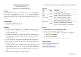
 Versiton SF70460MP Owner's manual
-
 vikings SMG820-D2 Installation guide

