Page is loading ...

Froling Heizkessel- und Behälterbau Ges.m.b.H, Industriestraße 12, A-4710 Grieskirchen
Tel +43 (0) 7248 606-0 Fax +43 (0) 7248 606-600 [email protected] www.froeling.com
4
Owner´s Manual
S3 Turbo
Read and follow the operating instructions and safety information!
Subject to technical change!

Table of Contents
1 Overview 6
1.1 Front view 6
1.2 Back view 7
1.3 Cross-section 8
1.4 Boiler manufacture and testing 9
1.5 Wood heater description and compliance status 9
1.6 Cleaning kit provided 9
2 Safety 10
2.1 Explanation of symbols 10
2.2 Permitted Uses 11
2.3 Requirements at the place of installation 13
2.3.1 Approval for the heating system 13
2.3.2 Space required 13
2.3.3 Requirements for central heating water 14
2.3.4 Ventilation requirement for boiler room 15
2.3.5 Requirements for the heating system 15
2.3.6 Requirements for the boiler room 15
2.3.7 Combination with thermal storage 16
2.3.8 Return temperature control 16
2.3.9 Requirements for the chimney connection 17
Basic data for designing the chimney connection
17
2.4 Safety markers 18
2.4.1 Mandatory signs 18
2.4.2 Prohibitions 19
2.4.3 Warning signs 19
2.4.4 Signage on the boiler 20
Notice of risks during installation
20
Notice of risks during operation
21
Notice regarding procedures in an emergency
22
2.5 Residual risks 23
2.5.1 Basic risks 23
2.5.2 Risks from electricity 23
2.5.3 Danger from fire and explosion 24
2.5.4 Danger from high temperatures 25
2.5.5 Risks from flue gases, lubricants and other equipment 26
2.6 What to do in the case of danger 27
2.7 Staff requirements 28
2.8 Personal protective equipment 30
2.9 Replacement parts 30
2.10 Environmental protection 31
2.11 The operator's responsibilities 31
3 Description of the boiler 33
3.1 Front view 33
Table of Contents
2 Froling GesmbH | A-4710 Grieskirchen, Industriestraße 12 | www.froeling.com

3.2 Back view 34
3.3 Cross-section 35
3.4 Functional description 36
3.5 Permitted fuels 38
3.6 Non-permitted fuels 38
4 Transport, Installation und Initial start-up 39
4.1 Safety 39
4.2 Conditions for initial start-up 39
5 Heating the boiler 40
5.1 Safety instructions for heating 40
5.2 Operation via the boiler controller 41
5.2.1 Control keys and display 41
Navigation keys
41
Status LED
41
Graphic display
42
Function keys
43
5.2.2 Setting parameters 45
5.3 Before heating up the boiler 46
5.3.1 Always move the WOS lever 46
5.3.2 Reloading intervals 46
5.3.3 Conversion tables and right amount of fuel 46
5.3.4 Fuel table 48
5.3.5 Fill level in boiler 48
5.3.6 Reloading intervals when operating without thermal storage or if the thermal storage is too
small
48
5.4 Heating up the boiler 49
5.5 Add more firewood during the operation 53
5.6 Remove ash 55
6 Maintaining the boiler 57
6.1 Safety instructions for maintenance 57
6.2 Securing the system so that it cannot be switched on again 58
6.3 Maintenance schedule 58
6.4 Maintenance work 59
6.4.1 Checking the safety equipment 59
Checking the system pressure
59
Checking the safety valve
59
6.4.2 Remove ash 60
6.4.3 Cleaning the grate 62
6.4.4 Cleaning the flue gas temperature sensor 63
6.4.5 Cleaning the low-temperature carbonization gas duct 63
6.4.6 Cleaning the primary air openings 64
6.4.7 Set and check the seal on the doors 65
Adjusting the doors
67
6.4.8 Cleaning the heat exchanger pipes 68
6.4.9 Cleaning the induced draft fan 70
6.4.10 Disposing of ash 71
6.4.11 After maintenance 72
Table of Contents
Owner´s Manual S3 Turbo | B1390016_en-us 3

7 Boiler faults 73
7.1 Safety instructions for troubleshooting 73
7.2 Troubleshooting table 73
7.2.1 Reset the high-limit thermostat. 74
7.3 After troubleshooting 74
8 Dismantling and disposal 75
9 Technology 76
9.1 Dimensions 76
9.2 Components and connections 77
9.3 Technical data 78
Table of Contents
4 Froling GesmbH | A-4710 Grieskirchen, Industriestraße 12 | www.froeling.com

Supplementary instructions
These instructions ensure safe and efficient use of the S3 Turbo (hereinafter referred
to as the “system"). These instructions are a component part of the system and must
be kept next to the system and within the immediate reach of staff at all times.
Staff must carefully read and understand these instructions before commencing all
work. All the safety instructions and operating guidelines specified in this manual must
be observed to ensure safety at work. In addition, the local accident prevention regula‐
tions and general safety regulations apply to the area of application of the system.
Images in these instructions are intended solely to aid understanding and may differ
from the actual design.
NOTICE
SAVE THESE INSTRUCTIONS!
Copyright
This instruction manual is protected by copyright.
This instruction manual must not be transferred to third parties, reproduced in any
form – even excerpts thereof – or the contents used and/or disclosed without the writ‐
ten consent of Fröling Ges.m.b.H. (hereinafter “manufacturer”), unless for internal pur‐
poses. Failures to comply with this shall incur damages. The manufacturer reserves
the right to assert further claims.
The manufacturer holds the copyright.
© Fröling Ges.m.b.H.
Supplementary instructions
Owner´s Manual S3 Turbo | B1390016_en-us 5

1 Overview
1.1 Front view
1 Boiler S3 Turbo
2 Boiler controller control panel
3 WOS lever
4 Actuator of primary air flap
5 Actuator of secondary air flap
6 Heat exchanger cleaning door
1
Overview
Front view
6 Froling GesmbH | A-4710 Grieskirchen, Industriestraße 12 | www.froeling.com

1.2 Back view
1 Boiler flow connection
2 Induced draft fan
3 Thermal discharge safety device connection
4 Drainage
5 Boiler return connection
Overview
1
Back view
Owner´s Manual S3 Turbo | B1390016_en-us 7

1.3 Cross-section
1 Insulated door
2 Fuel-loading chamber door
3 Pre-heating chamber door
4 Combustion chamber door
5 Fuel-loading chamber
6 Combustion chamber
7 Heat exchanger with spiral springs
8 In flue gas nozzle: Flue gas temperature sensor and broadband lambda probe
1
Overview
Cross-section
8 Froling GesmbH | A-4710 Grieskirchen, Industriestraße 12 | www.froeling.com

1.4 Boiler manufacture and testing
Your boiler was manufactured by Froling, a world leader on hot water (hydronic) heat‐
ing for over 50 years. The S3 Turbo boiler confirms to traditional high standards for
quality and reliability. It offers modern fire wood boiler technology with operating effi‐
ciencies of over 90% based on net calorific value of fuel. If treated properly and oper‐
ated according tot he guidelines in this manual, it will provide years of safe, dependa‐
ble and cost-effective heating.
S3 Turbo boilers are designed and built in accordance with European standard EN
303-5. This unit was safety and performance tested and listed to ANSI/UL 2523-2013
and CAN/CSA B415.1-10 by OMNI Test Laboratories, Inc; Portland, Oregon. The in‐
staller should follow local or state installation requirements.
The S3 Turbo fire wood boiler is designed and constructed for the highly efficient com‐
bustion of fire wood. Do not burn other fuels in the fire wood boiler S3 Turbo. The S3
Turbo boiler is a not self-contained, weather-tight boiler. It should be installed within
the heating building. S3 Turbo boilers should be installed with a thermal storage tank
system.
1.5 Wood heater description and compliance status
The S3 Turbo wood boiler is a down-draft type wood gasification boiler with an output
rating of between 51,250 btu/h and 102,500 (30 kW), or between 85,000 btu/h and
170,000 btu/h (50 kW). This appliance is not fitted with a catalytic combustor. This ap‐
pliance meets the 2015 US Environmental Protection Agency´s cord wood emissions
limits for wood heaters sold after May 15, 2015.
1.6 Cleaning kit provided
The cleaning kit below is provided for cleaning the boiler:
▪
Furnace tool
▪ Ash shovel
▪ Cleaning brush (Ø 53 mm)
▪ Cleaning brush (30 x 20 mm)
Overview
1
Boiler manufacture and testing
Owner´s Manual S3 Turbo | B1390016_en-us 9

2 Safety
2.1 Explanation of symbols
Safety information
Safety information in these instructions is indicated by symbols. The safety information
is preceded by signal words which reflect the extent of the risk.
DANGER
This symbol and signal word combination indicates a hazardous situation which will
lead to death or serious injury if it is not avoided.
WARNING
This symbol and signal word combination indicates a hazardous situation which could
lead to death or serious injury if it is not avoided.
CAUTION
This symbol and signal word combination indicates a hazardous situation which could
lead to slight or minor injuries if it is not avoided.
NOTICE
This signal word indicates important, but not safety-related information e.g. damage
to property or pollution
Safety information in operating instructions
Safety information can refer to certain, individual operating instructions. To avoid dis‐
rupting the flow of the text when you are performing the action, this safety information
is not incorporated in the operating instruction. The signal words set out above are
used.
Example:
❒ Undo screw
❒ CAUTION! Pinching hazard at cover
Take care when closing the cover.
❒ Tighten the screw
Special safety information
The following symbols are used to draw your attention to particular hazards
Tips and recommendations
Italics indicate useful tips and recommendations as well as information for efficient and
smooth running.
2
Safety
Explanation of symbols
10 Froling GesmbH | A-4710 Grieskirchen, Industriestraße 12 | www.froeling.com

Other markers
The following markers are used in these instructions to highlight operating guidelines,
results, lists, references, and other elements:
Marker Explanation
❒ Step-by-step operating instructions
➥ Results of actions
▪
Lists without a specified order
[Button]
Operating elements (e.g. button, switch), dis‐
play elements (e.g. signal lights)
“Display“ Screen elements (e.g. buttons, assignment of
function keys)
Units used
All units of measure are specified in these operating instructions in both SAE units and
SI units. The SAE unit appears first, followed by the SI unit in brackets.
Example using information about heat output: 17 (5) BTU/h (kW) equals
17 BTU/h (SAE system) or 5 kW (SI system).
2.2 Permitted Uses
The S3 Turbo boiler is designed exclusively for heating domestic water. Only use
those fuels specified in the “Permitted fuels” section.
Permitted use includes compliance with all the specifications in this instruction man‐
ual.
Any use other than or above and beyond the permitted use is considered misuse.
Safety
2
Permitted Uses
Owner´s Manual S3 Turbo | B1390016_en-us 11

WARNING
Danger of misuse
❒
Do not install the system in a mobile home.
❒ Do not operate the system in an explosive atmosphere.
❒ Keep the air inlet to the boiler room clear at all times.
❒ Only use fuels permitted by the manufacturer.
❒ Never store flammable materials close to the boiler.
❒ Never set flammable objects on the boiler to dry (e.g. clothing).
❒ Do not use any hydrogen halides or cleaning agents containing chlorine in the
boiler installation room.
❒ Keep covers and doors closed during operation.
❒ The chimney is only to be used as an outlet for one heating system.
❒ Do not use the hot water directly in swimming pools or thermal baths and do not
use as drinking water.
❒ Do not alter the boiler controller.
❒ DO NOT BURN GARBAGE, GASOLINE, NAPHTA, ENGINE OIL OR OTHER IN‐
APPROPRIATE MATERIALS.
❒ DO NOT USE CHEMICALS OR FLUIDS TO START THE FIRE.
❒ DO NOT OPERATE WITH FLUE DRAFT EXCEEDING 0.12 INCHES WATER
COLUMN (30 Pa).
❒ UNSAFE TO ADJUST FLUE DRAFT HIGHER THAN 0.12 INCHES WATER
COLUMN (30 Pa).
❒ THE HEAT EXCHANGER, DRAFT INDUCES, FLUE PIPE, AND CHIMNEY
MUST BE CLEANED REGULARLY TO REMOVE ACCUMULATED CREOSOTE
AND ASH. ENSURE THAT THE HEAT EXCHANGER, FLUE PIPE, AND CHIM‐
NEY ARE CLEANED AT THE END OF HEATING SEASON TO MINIMIZE COR‐
ROSION DURING THE SUMMER MONTHS. THE APPLIANCE, FLUE PIPE,
AND CHIMNEY MUST BE IN GOOD CONDITION. THESE INSTRUCTIONS AL‐
SO APPLY TO A DRAFT INDUCER IF USED.
➥ Misuse of the boiler can create hazardous situations.
2
Safety
Permitted Uses
12 Froling GesmbH | A-4710 Grieskirchen, Industriestraße 12 | www.froeling.com
2.3 Requirements at the place of installation
2.3.1 Approval for the heating system
The appropriate supervisory authority (inspection agency) must always be informed
when installing or modifying a heating system, and authorization must be obtained
from the building authorities. Also observe ANSI/NFPA 211 and CAN/CSA B365 for
the installation.
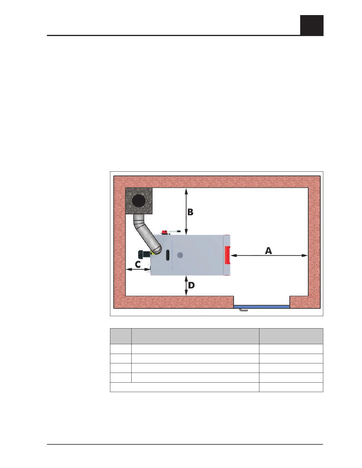
2.3.2 Space required
FOR SAFE INSTALLATION AND OPERATION CLEARANCES TO COMBUSTIBLES
MUST BE MAINTAINED.
The diagram below shows how much space is required for the system in the boiler
room.
The boiler may only be installed on non-combustible floors with these clearances.
Dimen‐
sion
Name S3 Turbo
A Distance - front of boiler to wall 36“ (900 mm)
B Distance – side of boiler to wall 32“ (800 mm)
C Distance – back to wall 14“ (350 mm)
D Distance – side of boiler to wall 9“ (250 mm)
Distance between ceiling and boiler 18“ (460 mm)
Safety
2
Requirements at the place of installation
Owner´s Manual S3 Turbo | B1390016_en-us 13

2.3.3 Requirements for central heating water
Water quality
Water of the following quality is required for the first fill:
▪ The water must be clean, pure or purified as well as odorless and must not contain
suspended matter.
▪ The water hardness must not exceed 190 grain/fl.oz. or 100 ppm CaCO
3
(100 mg/L), i.e. soft water is required.
▪ The chlorine concentration in the water must not exceed 58 grain/fl.oz. (30 mg/L).
▪ The pH value in the heating system must be between 8.0 and 8.6.
▪ If the water quality is too poor, use additives to prepare the water. If you are top‐
ping up with small amounts, always use clean water.
NOTICE
The hot water must not be used directly in swimming pools or thermae. Use a heat
consumer of the right size to consume the heat. Do not use the heating water as
drinking water.
To ensure good water quality during operation, avoid leaks and use a closed heating
system. If necessary, use a return temperature control.
First fill
To prevent air from getting into the heating system during the first fill, fill the filling
hose with water.
Frost protection
You can add anti-freeze to the heating water, however, this can reduce the heating ef‐
ficiency. Always follow the manufacturer’s dosing instructions when using anti-freeze,
as using the incorrect amount can cause corrosion. Check the concentration of the an‐
ti-freeze at regular intervals.
2
Safety
Requirements at the place of installation
14 Froling GesmbH | A-4710 Grieskirchen, Industriestraße 12 | www.froeling.com

2.3.4 Ventilation requirement for boiler room
Introduction
The external combustion air must meet certain requirements to ensure that adequate
combustion air is supplied to the boiler and no by-products from the combustion get
into the boiler room.
Ventilation air for the boiler room must be taken from and expelled directly outside,
and the openings and air ducts must be designed to prevent weather conditions (e.g.
from foliage or snowdrifts), plants or animals from obstructing the air flow. Permanent
ventilation is required to ensure that the boiler runs smoothly.
In North America there are several regulations which govern the minimum require‐
ments of combustion air for chimneys.
The boiler must be installed in such a way that it receives adequate ventilation and
combustion air and that the fuel in the boiler burns. The exhaust air must be expelled
safely outside via the chimney and maintained within a safe temperature range.
Boiler rooms are usually so small that normal ventilation does not provide enough air
and air must be brought in from outside. External air openings and air channels must
be of an appropriate size to supply adequate combustion air. The design must comply
with NFPA 211.
Consult your local chimney inspector for the installation and install the boiler in accord‐
ance with the applicable local regulations.
Recommended size of air openings according to NFPA 54 and NFPA 211:
The boiler requires a fresh air supply of between 1 sq.in. per 2,500 BTU/h and
1 sq.in. per 4,000 BTU/h (550 mm²/kW and 880 mm²/kW), depending on local condi‐
tions and the climate zone. Local conditions may necessitate an additional air supply.
2.3.5 Requirements for the heating system
▪ The whole heating system must be designed in accordance with relevant national
and local regulations.
▪
The boiler’s nominal load must be adjusted to the calculated heating requirements
of all the consumer loads connected in the heating circuit in summer and winter.
▪ The heating system must be big enough to transport the heat generated by the
boiler and an additional heat source (if present). The pressure throughout the
whole system including all heating zones must be even.
▪ Special equipment must be available for filling and ventilating the heating circuit.
Flow valves and zone valves must be fitted to set the correct water flow volume.
▪ All fitted pipes must be water-tight and air-tight and safely insulated.
▪ If there is a risk of parts of the heating system freezing, add anti-freeze to the wa‐
ter in these heat zones.
2.3.6 Requirements for the boiler room
▪ There must not be a potentially explosive atmosphere in the boiler room as the
boiler is not suitable for use in potentially explosive environments!
▪
The boiler room must be frost-free.
Safety
2
Requirements at the place of installation
Owner´s Manual S3 Turbo | B1390016_en-us 15

▪ There is no lighting on the boiler. Therefore, the customer must provide sufficient
lighting in the boiler room in accordance with national workplace design regula‐
tions.
▪
Always consult the manufacturer when using the boiler at more than 2000 meters
above sea level.
▪ Always keep the air suction opening of the boiler free from dust.
▪ The boiler room must be at least (mm) high.
2.3.7 Combination with thermal storage
Your S3 Turbo boiler must be installed with a Thermal Storage System. The purpose
of the thermal storage system is to absorb heat produced by the boiler if the building
load cannot use all of the heat being produced. This means that the boiler will be
batch fired. Batch firing requires that the boiler only be loaded with fuel and ignited
when the thermal storage temperature is depleted adequately so that it can absorb the
energy produced from the next fire. There may be some instances when the heating
load will use all of the heat being produced by the boiler. In such cases, the boiler may
be loaded continuously.
Your boiler is equipped with a timer that provides feedback about how many hours of
run time (active burning) or slumber time (boiler is stopped because no heat is being
taken from it) are accumulating. Slumber hours should be minimized as much as pos‐
sible. If you find slumber hours increasing, it is likely that you are over-filling the boiler
with wood and it is cycling on and off rather than having continuous run times.
Over filling the boiler may result in corrosion of the firebox wall, damage to the com‐
bustion chamber, damage to the firebox aprons, soot accumulation in the heat ex‐
change and dirty emissions.
Your thermal storage system may require periodic maintenance. Please review the
periodic maintenance requirements of your thermal storage system with your installer.
2.3.8 Return temperature control
It is recommended you fit a return temperature control when installing the heating sys‐
tem. If the hot water return is below the minimum return temperature, some of the hot
water outflow will be mixed in via the return temperature control.
NOTICE
Risk of dropping below dew point/condensation formation if operated without return
temperature control.
The manufacturer stipulates using a return temperature control. The minimum return
temperature is 140°F (60°C). It is recommended you fit some kind of control device
(e.g. thermometer). The controller of the return temperature control can be integrated
in the boiler controller.
❒ Condensation water forms an aggressive condensate when combined with com‐
bustion residue, leading to damage to the boiler. If the outside temperature is low,
condensation water can freeze at the chimney outlet, which can result in inade‐
quate chimney escape, limited boiler output and a system breakdown.
2
Safety
Requirements at the place of installation
16 Froling GesmbH | A-4710 Grieskirchen, Industriestraße 12 | www.froeling.com

2.3.9 Requirements for the chimney connection
The chimney connection must be big enough to channel flue gases from the building.
The whole flue gas system must be designed to prevent possible seepage, insufficient
feed pressure and condensation.
The manufacturer recommends fitting a draft regulator to limit the pressure to 0.12
inch WC (30 Pa). The draft regulator should be fitted directly on the chimney connec‐
tion where the pressure is very low.
The boiler must be connected to a brick chimney or a shop-made chimney in accord‐
ance with UL 103 HT (ULC S629 in Canada). The chimney must be clean and in good
condition at the time of installation.
The pipe unions within the chimney must be made of stainless special steel (with 304,
316 or 321 alloys). The flue gas connection pipe must be made of untreated steel or
stainless steel with a thickness of 24 Gauge. The minimum rise of the pipe must be ¼"
per foot for the progression towards the chimney. The chimney and the flue gas con‐
nection pipe must have a diameter of at least 6" (150 mm). The individual pipe sec‐
tions must be joined together with at least three self-tapping screws and the joins
sealed using high-temperature silicone. The flue gas pipe must not contain more than
two 90° bends.
All connections must conform to NFPA 211. Consult your local chimney sweep for the
installation and install the boiler in accordance with the applicable local regulations.
The chimney connection, ventilation ducts and fresh air openings must not be closed
over or blocked.
The flue gas pipe must not be displaced by an attic, loft, fuel store or similar areas.
Basic data for designing the chimney connection
Name S3 Turbo
30 50
Flue gas temperature at nominal load °C 170 170
°F 340 340
Flue gas temperature at partial load °C 110 110
°F 230 230
Flue gas mass flow at nominal load kg/h 76 122
lb/h 167 270
Flue gas mass flow at partial load kg/h 43 65
lb/h 95 143
Required feed pressure at nominal load Pa 8 8
in WC 0.03 0.03
Maximum permissible feed pressure Pa 30 30
in WC 0.12 0.12
Flue pipe diameter mm 150 150
inches 6 6
Safety
2
Requirements at the place of installation
Owner´s Manual S3 Turbo | B1390016_en-us 17

CAUTION
ADJUSTMENT OF THE FLUE DRAFT HIGHER THAN 0.12 INCHES WATER COL‐
UMN (30 Pa) COULD CAUSE A FIRE TO BURN OUT OF CONTROL AND AN UN‐
SAFE CONDITION!
❒
Maximum permitted setting: 0.12 inches WC (30 Pa)
Ideal setting: 0.04 inches WC (10 Pa)
2.4 Safety markers
WARNING
Danger if signage is illegible!
❒
Ensure that all safety, warning and operating instructions are always in a clearly
legible condition.
❒ Replace damaged stickers and signs immediately.
➥ Over time stickers and signs can get dirty or otherwise unrecognizable which
means that dangers cannot be identified and the necessary operating informa‐
tion cannot be observed. This poses a risk of injury.
The following stickers are located in the work area. They refer to the area immediately
surrounding where they are affixed.
2.4.1 Mandatory signs
Refer to the operating instructions
Only use the indicated system once you have read the operating instructions.
Wear hearing protection
This sign indicates that hearing protection must be worn in the area concerned.
Wear protective gloves
This sign indicates that protective gloves must be worn in the area concerned.
Wear safety shoes
This sign indicates that safety shoes must be worn in the area concerned.
Wear a dust mask
This sign indicates that a dust mask must be worn in the area concerned.
Keep the doors closed
Keep the doors closed during operation.
Turning off the main switch
Switch off the main switch and take precautions to prevent accidental switching on be‐
fore carrying out work to the system
Switch off the main switch for the fuel infeed and take precautions to prevent acciden‐
tal switching on before entering the fuel storage room.
Securing the main switch
Switch off the main switch and secure with a padlock when carrying out maintenance
work to the boiler.
2
Safety
Safety markers
18 Froling GesmbH | A-4710 Grieskirchen, Industriestraße 12 | www.froeling.com

2.4.2 Prohibitions
Unauthorized access prohibited
Only persons authorized by the operator may enter the danger zone and fuel storage
room. Keep children away! Keep the fuel storage room locked and keep the access
key in a safe place. Protect the fuel from moisture.
No fire, open flames or smoking
Areas marked with this are at risk of fire or explosion. Keep ignition sources away from
these areas.
2.4.3 Warning signs
Automatic start-up
This sign indicates that there is a risk of the system starting up automatically. Work
may only be carried out in areas with this marking if the system has been secured.
Electric current
Only licensed electricians may work in workspace with this marking.
Unauthorized persons are not permitted to enter work areas with this marking or open
the cabinet with this marking.
Harmful or irritant materials
These materials can be irreparably harmful to health, trigger allergic reactions or irri‐
tate the mucous membranes.
Observe the information on the packaging and containers.
Danger from carbon monoxide
There is a risk of poisoning from a possible concentration of carbon monoxide in the
fuel storage room and boiler room. Ventilate the fuel storage room for at least 15 mi‐
nutes before entering. Two people must always be present when working in the fuel
storage room. The access door must be kept open at all times. Also wear a dust mask
because of the high dust levels.
Hand injuries
Keep hands away from areas bearing this warning.
There is a risk that your hands could get trapped, pulled in or otherwise injured.
Hot surfaces
Hot surfaces, such as hot system parts, may not always be obvious. Do not touch
these parts without protective gloves.
Risk of falling
There is a risk of falling in the fuel store because of slippery surfaces or fuel lying
about. Take extreme care and wear personal protective equipment.
Risk of injury at fans
Keep hands away from areas bearing this warning.
There is a risk that your hands could get trapped, pulled into or otherwise injured in
automatic fans.
Safety
2
Safety markers
Owner´s Manual S3 Turbo | B1390016_en-us 19

2.4.4 Signage on the boiler
Notice of risks during installation
S3 Turbo - WOOD FIRED GASIFICATION HYDRONIC FURNACE
A 851 01 16
INSTALLATION HAZARDS
Install, modify and use only in accordance with manufacturer’s manuals. Refer to authorities having jurisdiction for
proper installation. Contact local building and fire officials about restrictions and installation inspection in your area. If
there are no applicable local codes, follow ANSI/NFPA 211 and CAN/CSA B365. Special precautions are required
for passing the chimney through a combustible wall or ceiling.
Inspect and clean exhaust system, loading chamber, burning chamber, ash-pits, and heat exchanger frequently in
accordance with owner’s manual.
Basic boiler data for layout of chimney system
S3 Turbo
Quantity Unit 30 50
011 / 071 011 / 071 C° erutarepmet sag eulF
032 / 043 032 / 043 F° daol laitrap / detaR
56 / 221 34 / 67 h / gk wolf ssam sag eulF
341 / 072 59 / 761 h / bl daol laitrap / detaR
)nmuloc retaw sehcni 30.0( aP 8 noitcennoc sag eulf sreliob ta tfard muminiM
)nmuloc retaw sehcni 21.0( aP 03 noitcennoc sag eulf sreliob ta tfard mumixaM
)sehcni 6( mm 051 retemaiD rotcennoc sag eulF
)F° 091( C° 88 erutarepmet retaw mumixaM
)isp 03( rab 2 erusserp gnikrow elbawolla mumixaM
)isp 72.76( rab 5.4 erusserP tseT
Mimimum Pressure Relief Valve )h/utB 000,535( Wk 551 yticapaC
For detailed design information please refer to Installation Manual!
For unit specifications, see the plaque located directly on the boiler!
DANGER!
Working on electrical components may cause severe injuries from electric shocks!
WARNING!
The electrical system of the boiler shall be supplied from a double 115 V 60 Hz (nominal 230 V AC) 15 amp
branch circuit including neutral and earth connection. For wiring instructions please refer to installation Manual!
Chimney must be 6’’ (150 mm) diameter listed UL-103 HT or ULC-S629 residential all-fuel type or tile-lined
masonry. Flue connector pipe must be 6’’ (150 mm) diameter made of a minimum 24 MSG black steel.
Inadequate design, installation and maintenance of the flue gas system will lead to insufficient chimney draft and
could result in Danger of Life or Severe Injury caused by serious faults in combustion, e.g. explosivel
y
combustion of carbonization gases and flash fires!
This boiler requires fresh air for safe operation and must be installed so there are provision for adequate
combustion and ventilation air!
CAUTION!
DO NOT CONNECT THIS UNIT TO A CHIMNEY FLUE SERVING ANOTHER APPLIANCE!
LOAD FUEL CAREFULLY OR DAMAGE WILL RESULT.
REFER TO OWNER´S MANUAL. DO NOT ALTER THIS EQUIPMENT IN ANY WAY.
UNSAFE TO ADJUST FLUE DRAFT HIGHER THAN 0.12 INCHES WATER COLUMN (30 Pa).
MAY BE CONNECTED TO AN EXISTING BOILER SYSTEM.
Flooring must be a minimum 3/8’’ (10 mm) non-combustible material covering the installation clearance area! The
base shall be horizontally, planar and reinforced if required. For construction of base please mind the weight o
f
boiler, water content and wood fuel according Installation Manual!
This boiler is not for use with an automatic stoker
Connection to an existing boiler system in combination with heat storage only!
Use original spare parts only. Installation of non-licensed
replacement parts will void the warranty!
2
Safety
Safety markers
20 Froling GesmbH | A-4710 Grieskirchen, Industriestraße 12 | www.froeling.com
/


