Page is loading ...

DSP4000B+
Operating Manual
Part No: 141135 Manual Release 1.0 4 March, 2009
©2007 Eventide Inc., One Alsan Way, Little Ferry, NJ, 07643 USA
Harmonizer is a registered trademark of Eventide Inc. for its audio special effects devices incorporating pitch shift.
DSP4000B+ is a trademark of Eventide Inc.

This Page Intentionally Left Blank

The
DSP4000B+ Operating Manual
Page 1
Table of Contents
HOW TO USE THIS MANUAL ..............................................................................................................................................................................3
OVERVIEW AND QUICKSTART_____________________________________________________________________ 4
T
HE BIG PICTURE ................................................................................................................................................................................................4
KNOB
S, KEYS, AND JACKS ................................................................................................................................................................................5
The Front Panel 5
The Back Panel 8
G
ETTING AROUND AND ALTERING PARAMETERS .......................................................................................................................................11
Adjusting the Brightness and Contrast of the Display 11
The “Areas” of the DSP4000B+ 11
Understanding the Display and SOFT KEYS 13
Using the Cursor Keys, the SELECT Key, the NUMERIC KEYPAD, and the KNOB 15
Ganged Parameters 15
Using the Cursor Keys and the KNOB in the PROGRAM Area 16
Entering or Changing Text 17
Q
UICKSTART OR “NEARLY INSTANT GRATIFICATION”..............................................................................................................................18
Hooking Up 18
Setting Input Levels 20
Effecting Things 21
“Panic” Muting 21
Loading Programs 21
Parameters 22
“Tweaking” and Saving “Tweaks” 23
Wrap Up 24
OPERATION _____________________________________________________________________________________ 25
Mounting and Handling 25
Memory Cards 25
Controlling Levels 27
The Level Meters 27
Controlling the Level of the Analog and Digital Inputs 28
Wet/Dry Ratios and Output Levels For the DSP4000B+’s Processor 29
Controlling the Level of the Analog and Digital Outputs 29
D
IGITAL SETUP ..................................................................................................................................................................................................30
Digital Setup Overview 30
S/P DIF & AES/EBU 30
Sampling Rates 30
Using the Internal Clock 31
Selecting The Internal Clock’s Rate 31
The Status Of The Digital I/Os When Using The Internal Clock 32
Understanding The “System Sampling Rate And External Sync Indicator” When Using The Internal Clock 32
Using an External Clock 33
Selecting The External Clock 33
The Status Of The Digital I/Os When Using The External Clock 33
Understanding The “System Sampling Rate And External Sync Indicator” When Using The External Clock 34
B
YPASSING AND MUTING .................................................................................................................................................................................34
E
XTERNAL CONTROLLERS ...............................................................................................................................................................................36
Setting Up the External Controllers 36
Foot Pedals 1 and 2 36
MIDI Setup 37
External Modulation and Trigger Menu Pages 39

The
DSP4000B+ Operating Manual - Contents
Page 2
“Manually” Selecting an External Controller For Modulation 40
External Controller Selection 42
“Automatically” Selecting a MIDI External Controller 43
Scaling the External Controller 43
The Concept Behind “Redirection” - Mods 1-4 and Trigs 1 &2 47
Remote Controlling Parameters 50
MIDI Groups 50
Configuring the MIDI Group 52
P
ROGRAM LOAD, SAVE, DELETE, ETC. ..........................................................................................................................................................53
Banks 53
Creating a New Bank or Renaming an Old Bank 54
The “Size” of a Program and Its Ramifications for Storage 54
Loading Programs 54
Loading a Program Remotely 55
Loading A Program Via A MIDI Program Change Message 55
Changing Banks Via A MIDI Controller Message 55
Triggering the Next or Previous Program To Load 55
Saving a Program 56
Copying Programs 56
Updating a Program 57
Renaming A Program 57
Deleting a Program 57
“Linking” Programs 58
Comparing a Currently Loaded Program With The Original (Saved) Version 59
P
ARAMETERS.......................................................................................................................................................................................................60
Taps 60
Textblocks 61
Graphics and Curves 61
Storing and Loading Setups 62
Miscellaneous Setup Options 63
APPENDIX A -UTILITIES__________________________________________________________________________ 64
T
RANSMITTING AND RECEIVING DATA..........................................................................................................................................................64
Setting Up the Serial Port 64
Dumping Data and Receiving Data Dumps 65
Controlling One DSP4000B+ from Another DSP4000B+ 66
Sending A Program From One DSP4000B+ to Another 66
Sequencing With MIDI 67
C
ONNECTING USER-SUPPLIED CRYSTALS AND EXTERNAL CLOCKS............................................................................................................68
S
ERVICE AND START-UP OPTIONS ..................................................................................................................................................................69
Fixing Internal Memory Problems 69
Fixing Memory Card Problems 70
Changing the Internal Battery 71
Clear Setup 71
Software Version and Accessories 71
Start-Up Options 72
ELECTRICAL SPECIFICATIONS ___________________________________________________________________ 73
WARRANTY INFORMATION ______________________________________________________________________ 75
INDEX___________________________________________________________________________________________ 77

The
DSP4000B+ Operating Manual
Page 3
IMPORTANT SAFETY INFORMATION
Before powering up the unit, check that the voltage selector on the back panel is set correctly.
Do not remove any covers or panels from the unit when the power is connected.
No operator access to the internals of the unit is permitted - servicing must be performed by qualified
personnel only.
The unit must not be operated with a damaged or ungrounded power cord.
Suitable ventilation must be provided for the unit at all times. In particular, the rear and side vents must
not be obstructed.
HOW TO USE THIS MANUAL – READ THIS FIRST
The first and second chapters of this manual are the most important ones. The first is the Overview and
Quickstart chapter. In it you will find essential information regarding the front panel, the back panel, and
the general structure of the DSP4000B+. After these preliminaries are out of the way, you’ll start using the
DSP4000B+ and learning the basic methodologies that you will employ whenever you use the DSP4000B+.
The Overview and Quickstart chapter is not meant to be complete. It’s meant to get you up and running
fast, circumventing thornier issues in favor of speed. If you would like to know more about a particular
topic discussed in this chapter, look to the abundant references contained therein. They’ll point you to
“chunkier” discussions in the remainder of the manual.
Ideally, we would have you read through the Overview and Quickstart guide with the DSP4000B+ in
front of you, following the examples. After you finish the Quickstart guide, we’d have you play with the
DSP4000B+ for awhile. Once the initial “new box euphoria” wore off a bit, we’d have you sit down and
read the Operation chapter. A true appreciation and mastery of the DSP4000B+ cannot be obtained with-
out reading the manual! We’d have you consult the appendices only when you need specific, technical in-
formation. Finally, when you need to find information days, weeks, months, and years down the road, we’d
have you use the comprehensive Table of Contents and Index.

The
DSP4000B+ Operating Manual
Page 4
OVERVIEW AND QUICKSTART
THE BIG PICTURE
The Eventide DSP4000B+ is a programmable, multipurpose, 24-bit/96kHz digital audio signal processor
with UltraShifter™ capability and is the stereo, single-processor companion product range to the Eventide’s
Orville. That’s a lot of adjectives! It is the successor to a long, proud line of digital signal processors that
stretches back to a time when most audio manufacturers didn’t know digital audio from Morse code.
We’ve loaded the DSP4000B+ with features that put it in a class by itself. The variety and depth of its pro-
grams are truly amazing, from lush reverbs, to choruses, to flanges, to delays, to pitch shifters, to dynamics,
to EQs, to filters, to distortions, to synthesizers, to samplers, to ring modulators, and to everything in-
between. The DSP4000B+ can do it all. And if that’s not enough, the DSP7500 boasts nearly three minutes
of sample time in addition to the 40 seconds of delay time!
And for the user who is interested in making his or her own programs (if the huge number of factory pro-
grams aren’t enough!), the DSP4000B+ continues the “modular programming paradigm” that made the
DSP4000 famous. Programs are composed of individual building blocks, or “modules,” that allow the user
to create original programs. Inspiration and creativity are given no bounds. . .

The
DSP4000B+ Operating Manual
Page 5
KNOBS, KEYS, AND JACKS
If this is your first time learning the DSP4000B+, don’t be put off by some of the rather in-depth descrip-
tions that will follow; they exist for your future reference (
once you understand the DSP4000B+ and need a quick bit of infor-
mation
). For now, concentrate on what the various knobs and jacks are called. Their use will be explained pro-
gressively throughout the rest of this manual.
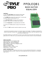
The Front Panel
A) Level Meters These measure the signals at the analog inputs, the digital inputs, the input and out-
put of the processor, the analog outputs, and the digital outputs. The highest LED
indicates a clipped signal, and every LED below that falls off at -3dB per decrement,
with the exception of the bottom one, which indicates the presence of any signal.
→ See The Level Meters on page 27.
B) System sampling rate and external sync indicator.
The top four LEDs display the system sampling rate of the DSP4000B+: 96 kHz,
88.2 kHz, 48 kHz, or 44.1 kHz. When solidly lit, they indicate that the system sam-
pling rate is exact (+/- 0.05%). When blinking, they indicate that the system sampling
rate is between one of the fixed rates (
the LED corresponding to the nearest sampling rate blinks).
The bottom LED, EXT, reflects the current external sync status (it blinks if there’s a prob-
lem
).
→ See Understanding The “System Sampling Rate And External Sync Indicator” When Using The Inter-
nal Clock on page 32.
→ See Understanding The “System Sampling Rate And External Sync Indicator” When Using The Exter-
nal Clock on page 34.
C) BYPASS Press this key to bypass or, depending on how you have your DSP4000B+ set up,
mute the machine.
→ See Bypassing and Muting on page 34.
D) SOFT KEYS These four keys select the menus or events described on the bottom line of the dis-
play.
→ See Understanding the Display and SOFT KEYS on page 13.

The
DSP4000B+ Operating Manual
Page 6
E) The display The display tells you what’s going on. The
top line displays the currently running
program and the display area you’re
working in. The bottom line is dedicated
to the four
SOFT KEYS directly below the display. The middle section of the display
changes depending on what you’re doing!
→ See Understanding the Display and SOFT KEYS on page 13.
F) CURSOR keys Press these keys to move the cursor on the display.
→ See Using the Cursor Keys, the SELECT Key, the NUMERIC KEYPAD, and the KNOB on page 15.
G) PROGRAM Press this key briefly to access program functions such as loading, saving, deleting,
etc.
→ See Program Load, Save, Delete, Etc. on page 53.
Press and hold this key for one second to access the Setup Storage area where “setup
configurations” are loaded and saved.
→
See Storing and Loading Setups on page 62.
H) PARAMETER Press this key briefly to access parameters for the program that is running.
Press and hold this key for one second to access the Patch Editor.
→ See the separate Programmer’s Manual for Patch Editor information.
J) SELECT Press this key briefly to select something highlighted by the cursor.
Press and hold this key for one second to set up a remote control for whatever pa-
rameter is highlighted on the display.
→ See Remote Controlling Parameters on page 50.
→ To change the “one second hold time,” alter the “key hold” parameter on the [misc] menu page in
the SETUP area (you may have to press the SETUP key several times to find it).
K) The
KNOB Spin the KNOB to change the value of whatever parameter is highlighted.
→ See Using the Cursor Keys, the SELECT Key, the NUMERIC KEYPAD, and the KNOB on page 15.
L) The NUMERIC KEYPAD
Use the numbers, decimal point, and minus sign to enter numeric values or to enter
numeric text in a text field. Use the CXL key to “cancel” the last entered digit (like a
backspace key on a computer
). Use the INC/DEC keys to increment or decrement a parame-
ter’s value. Use the ENT key after you’ve entered a numeric value.
→ See Using the Cursor Keys, the SELECT Key, the NUMERIC KEYPAD, and the KNOB on page 15.
M)
BUSY LED If a Memory Card is in place, this LED illuminates when data is being written to the
card. Don’t remove the Memory Card if this LED is lit! If no Memory Card is in
place, this illuminates when data is present at the MIDI In port or at the serial port.
Use the latter feature to troubleshoot communication problems between the
DSP4000B+ and the rest of the world.

The
DSP4000B+ Operating Manual
Page 7
N) Memory Card slot
Insert a Memory Card here to add new programs or to save your own. Press the re-
lease to the right of the slot to remove the card (but not when the busy LED is lit!).
→ See Memory Cards on page 25.
O) LEVELS Pressing this key accesses menus for metering and levels.
→ See Controlling Levels on page 27.
P) SETUP Pressing this key accesses menus for digital configuration, MIDI configuration, ser-
vice utilities, data dump utilities, and program advance options.
Q) POWER Flip this switch to bring the DSP4000B+ to life! When the power is off the unit is
bypassed, i.e., each audio input is connected to its corresponding audio output.

The
DSP4000B+ Operating Manual
Page 8
3
21
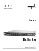
The Back Panel
a) AC Voltage Selector
Line up the dot with the triangle so that your preferred voltage is up. It is absolutely
essential that you select the voltage corresponding to your local AC power!
b) Fuse Holder A 1-Amp Slow Blow fuse. Always replace it with the correct value.
c) AC Port Connect an IEC standard 3-prong AC power cord here. The center post is chassis
ground.
d) Analog Audio Inputs
The DSP4000B+’s analog inputs accept either unbalanced 1/4”
connectors or balanced XLR connectors. The DSP4000B+’s XLR
input connectors are female. Pin #1 is ground. Pin #2 is +phase
(hot) and Pin #3 is -phase.
To “unbalance” the XLR jack, use both pins #1
and
#3 as ground
and use Pin #2 as “hot.”
If either pins #2 or #3 are uncon-
nected, you will get more noise and hum than signal !
These may be used as both line and guitar inputs, depending on the input level set-
ting.
e) Analog Audio Outputs
The DSP4000B+’s XLR analog audio output jacks are male. Pin #1
is ground. Pin #2 is +phase (hot) and Pin #3 is -phase.
To “unbalance” the jack, use pins #1
and
#3 as ground and use
Pin #2 as “hot.”
If either pins #2 or #3 are unconnected, you
will get more distortion than signal !
→ See Controlling the Level of the Analog and Digital Inputs on page 28.
Do not connect these outputs to a phantom powered microphone input –damage
may be caused to either the DSP4000B+ or to the phantom power supply. The peak
output level from the DSP4000B+ will probably be too high for a low-level micro-
phone input.
3
2
1
1/4"

The
DSP4000B+ Operating Manual
Page 9
AES/EBU Digital Audio Input/Output (Professional)
Use these connectors to connect professional digital audio gear to the DSP4000B+. These cables are differ-
ential with a shielded twisted pair. Eventide recommends the use of purpose-manufactured Digital Audio
cables, which have low capacitance and a controlled impedance, for carrying AES signals.
Ordinary microphone cables will usually work at 48kHz, but are likely to reduce range and add jitter and
possible distortion to the signal. It is unlikely that microphone cable will prove satisfactory for 96kHz opera-
tion.
f) AES/EBU input jack
If the parameter DIG IN on the audio
menu page in the SETUP area is set to
AES/EBU, then digital inputs are accepted
at this jack.
g) AES/EBU output jack
If the parameter DIG OUT on the audio
menu page in the SETUP area is set to
AES/EBU, then both the AES/EBU and
S/P DIF outputs will use the “professional” digital format.
S/P DIF Digital Audio Input/Output (Consumer)
S/P DIF is a consumer digital audio standard, with two audio channels encoded into a single connector. Use
these connectors to hook up the DSP4000B+ to CD players, DAT recorders, and other audio gear using
this format. The connectors are two-conductor RCA jacks. Your plug should have the shield connected to
the sleeve with the single shielded conductor connected at the tip.
Eventide recommends the use of professional quality cables made of RG-59/U coaxial cable. Ordinary "hi-
fi" type leads will probably prove inadequate, especially at the higher sample rates.
h) S/P DIF input/output jacks
If the parameter
DIG IN on the audio
menu page in the SETUP area is set to S/P
DIF
, then digital inputs are accepted at
the S/P DIF input jack. If the parameter
DIG OUT on the audio menu page in the
SETUP area is set to S/P DIF, then both the AES/EBU and S/P DIF outputs will
use the “consumer” digital format.
→ See S/P DIF & AES/EBU on page 30.
j) WordClock In and Out
Use these jacks to sync the DSP4000B+ to wordclock or to output wordclock. → See
Using an External Clock on page 33.
k) Foot Pedal jacks 1 and 2
Stereo 1/4” connectors. The sleeve is ground reference, the ring is +5 volts (source),
and the tip is an analog signal from 0 to 5 volts. Connect either foot switches, foot
pedals, or control voltage sources to these inputs to modulate parameters or to trig-
ger events (including remote program loads).

The
DSP4000B+ Operating Manual
Page 10
→ See Foot Pedals 1 and 2 on page 36.
m) Relay Jack
Two relays are connected to this Stereo 1/4" connector. They can be controlled
from suitable programs, allowing the DSP4000B+ to drive real-world equipment,
and can switch up to 1.0A at 30V dc. Relay #1 is connected between ring and sleeve,
while Relay # 2 is connected between ring and tip. All of these connections are elec-
trically isolated from the DSP4000B+. See the separate Programming Manual for in-
formation on controlling the relays.
MIDI is used for instrument to instrument digital communications. The DSP4000B+ sends and receives
Eventide system exclusive messages that allow a MIDI sequencer to remote control the DSP4000B+,
among other things. In addition, the DSP4000B+ may respond to standard MIDI messages and may output
standard MIDI messages. The DSP4000B+ has three MIDI ports:
n) In The DSP4000B+ accepts (and processes) MIDI messages received at the MIDI In
port. The connector is “7 pin” and can provide power to a suitable pedal board, pro-
vided you supply power at the “Remote Power In” socket described below. It can
also send MIDI messages from this connector to a suitably equipped system. This
means, for example, that a pedal board can be connected to the DSP4000B+ by
means of a single cable that supplies power as well as a communication path. A nor-
mal "5 pin" MIDI cable can be used as a standard MIDI input.
o) Out The DSP4000B+ sends MIDI messages to other devices via the Out port.
MIDI mes-
sages are also sent out the serial port if they are “enabled.”
p) Thru Any MIDI information received at the MIDI In port is echoed directly to the MIDI
Thru port regardless of the DSP4000B+’s configuration (as long as the DSP4000B+ is
powered up) .
With the Memory Card removed, the BUSY LED on the front panel illuminates whenever a MIDI message is received
at the MIDI In port. Note: If the serial port is “enabled” and MIDI is “enabled,” a command received over either the
serial port or the MIDI In port causes the port not receiving the command to be ignored until the command is complete.
→ See MIDI Setup on page 37.
q) Serial Port An IBM PC type RS232 connector that looks like a modem or printer to a connected
computer. Connect a "9 pin" serial cable to this port to transfer information to and
from a personal computer (do not use the "null modem" type of cable designed for
file transfer between two computers - it will not work). With the Memory Card removed, the
BUSY LED on the front panel illuminates whenever a message is received at the serial port. Note: If the serial port is
“enabled” and MIDI is “enabled,” a command received over either the serial port or the MIDI In port causes the port
not receiving the command to be ignored until the command is complete.
→ See Setting Up the Serial Port on page 64.

The
DSP4000B+ Operating Manual
Page 11
GETTING AROUND AND ALTERING PARAMETERS
Adjusting the Brightness and Contrast of the Display
Before we begin to describe the DSP4000B+’s interface, we
ought to make sure you can see the display! Adjust the contrast of
the display by pressing the SETUP key, then the SETUP key again,
and then the leftmost SOFT KEY. Turn the KNOB to adjust
contrast or press the DOWN CURSOR key and turn the KNOB to adjust brightness.
The “Areas” of the DSP4000B+
The DSP4000B+’s interface is divided into several functional “areas.” You access each area by pressing its
key. You’ll know which area you’re in because the LED next to its key will be illuminated. The areas are:
PROGRAM Press the PROGRAM key to access this
area. Inside you’ll find utilities for loading
programs, saving programs, deleting
programs, comparing a tweaked program
with the saved version, and creating banks (“manila folders” for organizing pro-
grams). Press the PROGRAM key to access additional SOFT KEYS.
→ See Program Load, Save, Delete, Etc. on page 53.
SETUP Storage Press and hold down the PROGRAM key
for one second to access this area. The
LED next to the PROGRAM key blinks.
Inside you’ll find utilities for loading, sav-
ing, or deleting “setups.”
→ See Storing and Loading Setups on page 62.
→ To change the “hold time," see Miscellaneous Setup Options on page 63.

The
DSP4000B+ Operating Manual
Page 12
PARAMETER Press the PARAMETER key to access this
area. Here you’ll find the parameters for
the currently loaded programs. Continue
pressing the PARAMETER key to access
additional
SOFT KEYS (if available).
→ See Parameters on page 60.
The PARAMETER key also gives access to the built-in Patch
Editor. Press and hold down the PARAMETER key for one
second to access this area. The LED next to the PARAMETER key
blinks. The Patch Editor allows you to create your own effects
from scratch or to customize programs that already exist.
→ See the separate Programmer’s Manual for more information on the Patch Editor.
→ To change the “hold time," see Miscellaneous Setup Options on page 63.
LEVELS Press the LEVELS key to access this area.
Inside you’ll find level and Level Meter pa-
rameters.
→ See Controlling Levels on page 27.
SETUP Press the SETUP key to access this global,
“catch-all” area. Inside you’ll find digital
setup controls, global MIDI setup, global
“external” setup, display con-
trast/brightness, the pedal jacks’ setup,
dump data utilities, next/previous program advance, and miscellaneous service utili-
ties. Press the SETUP key more than once to access additional SOFT KEYS.

The
DSP4000B+ Operating Manual
Page 13
Understanding the Display and SOFT KEYS
Every “area” in the DSP4000B+ makes use of the display, so understanding the display is critical. A generic
screen of the sort typically found in the
PARAMETER area is shown below. It exemplifies various aspects of
the display that remain constant no matter what area of the DSP4000B+ you’re in.
The upper left-hand corner of the display always shows the name of the program currently running. In the
example shown above, we’re running the program “
Centering Echoes.” The upper right-hand corner of
the display always describes the menu page you’re looking at. In the example shown above, we’re looking at
the “tone controls” menu page.
Situated along the bottom of the display are the so-called “SOFT KEYS.” The four physical keys located be-
low the display select menu pages or events corresponding to these
SOFT KEYS. (They’re called “soft” be-
cause their function changes depending on context.) The “More soft keys” indicators are the little arrows
next to the SOFT KEYS shown above. They indicate that if you press the “area” key you used to access the
current display again, you will access more SOFT KEYS. The arrows are meant to imply that more pages exist
in a nether-world beyond the display. . .
For example, press the SETUP key to see the “More soft keys”
indicators.
Press the SETUP key again to get more SOFT KEYS.
Press the SETUP key twice more to return to the original set of
SOFT KEYS.

The
DSP4000B+ Operating Manual
Page 14
A “Stacked” SOFT KEY (such as pedals in the screen above) indicates that if you repeatedly press the
“stacked” SOFT KEY, you will access more menus. The graphic is meant to imply that there are more pages
lying “below” the “top” one.
For example, press the SETUP key. Press the stacked SOFT KEY
midi.
Press it again to get a second menu page.
Press it again to get a third menu page.
Press it twice more to return to the original menu page.
Pressing a SOFT KEY repeatedly that is not stacked puts the DSP4000B+ into “self-destruct” mode. Just
kidding. It has no effect.
When you press a SOFT KEY, it becomes highlighted. The middle section of the screen is a menu page cor-
responding to that highlighted SOFT KEY. Use the cursor keys to “move around” on the menu page. Use
the KNOB, the NUMERIC KEYPAD, and the SELECT key to change and enter values.
→ See Using the Cursor Keys, the SELECT Key, the NUMERIC KEYPAD, and the KNOB on page 15.
Before moving on, we ought to say that not all SOFT KEYS are
menu pages. Some SOFT KEYS are “triggers.” A “trigger” is a key
that triggers an event, get it? You’ll always know the difference be-
tween menu page SOFT KEYS and trigger SOFT KEYS because
menu page SOFT KEYS are rectangular, whereas trigger SOFT KEYS
are hexagonal. On this screen main and info are menu pages, and
<ring> is a trigger.

The
DSP4000B+ Operating Manual
Page 15
Using the Cursor Keys, the SELECT Key, the NUMERIC KEYPAD, and the KNOB
We use the CURSOR keys, the KNOB, the SELECT key, and the NUMERIC KEYPAD to navigate and manipu-
late the menu pages found in the
PARAMETER, Patch Editor, LEVELS, and SETUP areas. We’ll discuss their
use in the PROGRAM and SETUP Storage areas in a bit.
Use of the cursor keys is straightforward. The
LEFT and RIGHT CURSOR keys move the cursor left and
right, respectively. If you move the cursor “past the edge of the screen," it will “wrap” around to the other
side. The UP and DOWN CURSOR keys move the cursor up and down, respectively. Again, the top and bot-
tom “wrap” around.
Use the KNOB, NUMERIC KEYPAD, or the INC/DEC keys to alter the
value of a numeric
parameter. For example, spin the KNOB on this
screen to change the value of Mix or enter a new value directly with
the NUMERIC KEYPAD (pressing ENT when you’re done).
Use the
KNOB or the INC/DEC keys to alter the value of a text
parameter. For example, spin the KNOB or press the INC key to
change Shape from Sine to Triangle on this screen.
Numeric parameters and text parameters cover 99% of the
parameters you’ll see in the DSP4000B+, but there are a few more
esoteric parameters you’ll encounter. One such oddball is the
“trigger” parameter. “Triggers” trigger things to happen. You place
the cursor over a trigger parameter, and trigger it by pressing
SELECT. Other oddballs include “Taps” and “Graphics.”
→ See Taps on page 60.
→ See Graphics and Curves on page 61.
Ganged Parameters
In some cases there are multiple, related parameters that are usually
adjusted together. To make such “mass adjustments” easy, a
feature exists that gangs parameters together. The main menu page
in the LEVELS area contains a good example of ganged parameters.
The purpose of this menu page is to assign signal levels and
wet/dry ratios. Such assignments are typically made in stereo gangs. So, both parameters are initially ganged
together. Spin the KNOB and both values change.
Now, let’s say you only want to change
OUT 1. Press the DOWN
CURSOR
key to “ungang” the pair. Now spin the KNOB; only the
value for OUT 1 changes.
To get to a screen like this one, first press the PROGRAM
key. Scroll through the banks (using the LEFT or RIGHT
CURSOR keys and the KNOB) to “PHASERS." Scroll
through the programs in that bank to “Stereoizing-
Phaser." Load it and press the PARAMETER key.

The
DSP4000B+ Operating Manual
Page 16
Pressing the DOWN CURSOR key again allows you to adjust OUT 2, while pressing the UP CURSOR key re-
gangs the parameters. Gangs are much easier to use than to describe, so take a minute and play with the
gangs on this menu page. You will find gangs sprinkled liberally throughout the DSP4000B+ as their pres-
ence facilitates many tasks.
Using the Cursor Keys and the KNOB in the PROGRAM Area
Now, let’s investigate the use of the cursor keys and the KNOB in
the
PROGRAM area (they work just the same in the Setup Storage area). Things
are only a little bit different here than in the other areas. The box
on the display with the word “banks” in it is called the “bank
field.” The box below the banks field with the word “programs” in it is called the “programs field.” In the
PROGRAM area, the UP and DOWN CURSOR keys scroll through programs and the KNOB scrolls through
banks when the cursor is in the “bank field” (banks are “manila folders” for programs. See Banks on page 53).
The SELECT key, the <load> SOFT KEY, and the ENT key all load the program shown in the display with
the triangle next to its number
(you may need to press the PROGRAM key again to find the <load> SOFT KEY). For example:
Press either the LEFT CURSOR key when the cursor is in the
programs field (as on the above screen) to position the cursor
over the bank field (as shown to the right).
With the cursor in the bank field, spin the
KNOB to scroll through
banks.
Press the UP or DOWN CURSOR key to scroll through programs.
Spinning the KNOB also scrolls through programs, provided the
cursor is in the “programs field.”
Press the SELECT key, the <load> SOFT KEY, or the ENT key on
the numeric keypad to load the program shown in the display
with a triangle next to its number. On the screen to the right,
“
Singularity” has the triangle next to its number.
Pressing
SELECT, <load> SOFT KEY, or ENT would load it
and result in this screen. Notice that the upper left-hand corner of
the display reflects the fact that “Singularity” is now the
currently running program.
The moral of the story? Use the LEFT CURSOR key to position the cursor in the “banks field,” then use the
KNOB to scroll to the bank from which you want to load a program. Then use the UP and DOWN CURSOR
keys to scroll through programs to the particular program you want to load. When you get there, press the
SELECT key, the <load> SOFT KEY, or the ENT key.
→ To learn how to remotely load programs, read Loading a Program Remotely on page 55.

The
DSP4000B+ Operating Manual
Page 17
Entering or Changing Text
In some menus, it will be necessary to enter or change text. For example, you will often change text when
saving a new program. The method by which this is done is straightforward, albeit a bit tedious. To play along, go
to the
PROGRAM area and press the <save> SOFT KEY. (You may have to press the PROGRAM key a second time to see it.) Press the UP
CURSOR
key
twice, so that the box next to “name” is highlighted and press the SELECT key. To escape from this “pop-up” menu, highlight the
“
cancel” box and press the SELECT key.
Here’s how it works: Select the item that has the text you want
to add or change (with the cursor keys) and press the SELECT
key. Now the LEFT and RIGHT CURSOR keys move you
through the text string and the CXL key acts as a backspace key,
deleting characters as it moves back. Turn the KNOB to scroll
through alphanumeric characters. When you arrive at the character you want, stop scrolling and move the
cursor past that character. Begin scrolling again for the next character. When you are finished entering your
text, press the SELECT key or the ENT key to make it “stick.” The list of alphanumeric characters in order is:
; : / ? > < , ; ` ~ | \ _ = + - } { ] [ ‘ ) ( * & ^ % $ # @ ! z y x w v u t s r q p o n m l k j i h g f e d c b a space
A B C D E F G H I J K L M N O P Q R S T U V W X Y Z 0 1 2 3 4 5 6 7 8 9 . - %

The
DSP4000B+ Operating Manual
Page 18
QUICKSTART OR “NEARLY INSTANT GRATIFICATION”
All right, all right! Areas, displays, SOFT KEYS, parameter this, scroll that. . . BUT WHAT CAN IT DO?
Let’s cut to the chase and get you up and running! Besides, if you play with the box a good deal before mov-
ing on to the finer points of operation, those finer points will stick better to the ol’ gray matter. . .
Here are the steps we will take:
1. First, we’ll connect the DSP4000B+ to the rest of your gear.
2. On page 20 we’ll set the input levels so that things don’t distort.
3. On page 21 we’ll learn how to “mute” the DSP4000B+ in the event of feedback.
4. On page 22 we’ll run programs and “tweak” their parameters.
5. Finally, on page 23 we’ll learn how to save the programs you’ve “tweaked” for future use.
Hooking Up
The diagram above shows the signal flow through the DSP4000B+ and is discussed in detail on page 27.
But before we concentrate on what happens inside the DSP4000B+, we ought to get it hooked up to the rest
of your studio. As was stated in the overview, we have two analog inputs, two analog outputs, two digital
inputs, and two digital outputs all at our disposal all the time. The analog and digital inputs are summed be-
fore processing, and the output of the processor is always available at both the analog and digital outputs.
→ See The Back Panel on page 8 for information on the jack types and their specifications.
Hook up the analog inputs to suitable output sources, such as an analog mixer’s effect sends or the outputs
of a preamplifier. The connections may be made with either balanced XLR connectors or unbalanced 1/4”
connectors. You can plug a guitar into the 1/4" jacks, but you will need to turn up the input gain.
→ See Setting Input Levels on page 20.
Hook up the balanced analog outputs to suitable input recipients, such as an analog mixer or an amplifier.
Hook up the digital inputs to suitable output sources, such as a DAW (digital audio workstation) or a key-
board with digital outputs. The source of your digital signal must come from the same device (because a sin-
gle cable carries two channels) and is taken from either the AES/EBU input jack or the S/P DIF input jack
(see below to learn how to switch between the two).
/