
User's Information 1026W
H2355700A
MINI-THERM
User’s Information Manual
A. System Start Up
1. Verify that the pump system is operating
properly.
a. Shut off the manual gas valve.
b. Set the wall thermostat to a setting high
enough to call for heat.
c. The pump should come on immediately. If
it doesn’t, have a service technician test the
electrical circuits.
2. Light the pilot.
a. The JVS and JVH boilers do not require
manual lighting. The pilot is controlled by
the automatic ignition system.
b. Different models of the JV boiler utilize
various gas valves. Although the gas valves
may have different control knobs, they are
all similar in operation. The JVS gas valve
has a two-position knob - On and Off.
WARNING: If this Users Information
Manual not followed exactly, a re or explosion
may result causing property damage, personal
injury or death.
Do not store or use gasoline or other ammable
vapors and liquids in the vicinity of this or any
other appliance.
WHAT TO DO IF YOU SMELL GAS
• Do not try to light any appliance.
• Do not touch any electrical switch; do not use any
phone in your building.
• Immediately call your gas supplier from a
neighbor's phone. Follow the gas supplier's
instructions.
• If you cannot reach your gas supplier, call the re
department.
Installation and service must be performed by
a qualied installer, service agency, or the gas
supplier.
AVERTISSEMENT: Si cette informa-
tion utilisateurs manuel n'a pas suivi exactement,
un incendie ou une explosion peut entraîner des
dommages matériels, des blessures ou la mort
Ne pas entreposer ni utiliser d’essence ni d'autres
vapeurs ou liquides inammables dans le voisinage
de cet appareil ou de tout autre appareil.
QUE FAIRE SI VOUS SENTEZ UNE ODEUR DE GAZ:
• Ne pas tenter d’allumer d’appareils.
• Ne touchez à aucun interrupteur. Ne pas vous servir
des téléphones dansle bâtiment où vous êtes.
• Appelez immédiatement votre fournisseur de
gaz depuis un voisin. Suivez les instructions du
fournisseur.
• Si vous ne pouvez rejoindre le fournisseur de gaz,
appelez le service des incendies.
L’installation et l’entretien doivent être assurés par un
installateur ou un service d’entretien qualié ou par le
fournisseur de gaz.
JVH
JVS
Residential
Gas-Fired
Hydronic Boilers
Models JVH, JVS
Sizes 50-225
U.S. Patent No. 1,609,692
Canada Patent No. 383,318

Page 2
LAARS Heating Systems
Important: When lighting or relighting, wait the
full 5 minutes specied in the lighting instructions.
Unburned gases can accumulate in the re box and
may ash back. Allow ample time for natural air
movement to clear the gases from the chamber before
lighting or relighting.
Relighting - All Models:
1. Turn off electrical power to the boiler.
2. Turn the gas valve knob (clockwise for JVS) to
Off.
3. Wait ve minutes.
4. Turn the gas valve knob (counterclockwise for
JVS) to On.
5. Restore power to the boiler, and set the
thermostat to the desired temperature. The
pilot will automatically ignite when there is
a call for heat.
Circulator Pump:
In normal operation, the pump is energized by the wall
thermostat via the pump relay supplied with the boiler.
Caution: Hazard of electrical shock!
Disconnect power to the boiler before
servicing the relay or transformer.
B. System Shut Down
Turn off all gas valves and the electrical
disconnect switch. Whenever danger of freezing exists,
shut off the water supply, remove the drain plugs in the
left side of the heater and open the drain valve on the
right side. Drain every part of the system which might
be subject to freezing temperatures.
Should overheating occur or the gas supply fail
to shut off, do not turn off or disconnect the electrical
supply to the pump. Instead, shut off the gas supply at
a location external to the appliance.
En cas de surchauffe ou si l'admission de gas
ne peut être coupée, ne pas couper ni débrancher
l'alimentation électrique de la pompe. Fermer plutôt le
robinet d'admission de gas à l'extérieur de l'appareil.
To Shut Down Boiler:
(JVS and JVH) Automatic Ignition Systems:
1. Turn off power to the boiler and set the
thermostat to the lowest setting.
2. Turn the gas valve knob (clockwise for JVS) or
switch to the Off position.
C. Maintenance
1. Lubricate the water circulating pump according
to the instructions found on the pump.
2. If a strainer is employed in a pressure reducing
valve or in the piping, clean it every six months.
3. At start-up and periodically thereafter, the ame
should be observed for proper performance. If
the ame has “sooting” tips, check for debris
near the orices. If this continues, call a service
technician.
4. For JVS models, ensure proper operation of the
mechanical damper, mounted in the ue collar,
by observing the damper handle. Be sure the
handle swings when the draft inducer starts.
Depending on the boiler size, the swing may be
as little as 30°. Remove any obstructions and
clean around the pivot rod (handle) holes.
5. Inspect the venting system for obstructions,
leakage and corrosion at least once each year.
6. Keep the boiler area clear and free from
combustible material, gasoline and other
ammable vapors and liquids.
7. Be certain all combustion air and ventilation
openings are unobstructed.
8. Check for fouling on the external surfaces of the
heat exchanger every six months.
Fouling on the external surfaces of the heat
exchanger is caused by incomplete combustion
and is a sign of combustion air and/or venting
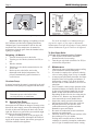
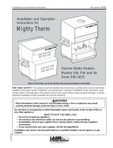
Figure 2 - Gas Control for JVH Models
ON
OFF
Gas Control Knob
Figure 1 - Gas Control for Automatic Ignition System (JVS)

Page 3
Mini-Therm JV
problems. As soon as any fouling is observed, the
cause of the fouling should be corrected.
The heat exchanger can be checked using a
ashlight by locating a mirror under the burners.
An alternate method is to remove the venting and
top panel as necessary to inspect from above.
Also, check the vent system for defects at this
time.
If cleaning is required:
a. Shut off all power to the boiler.
b. Expose the heat exchanger by removing the
draft hood (when equipped), and venting, top
assembly, ue collector, and heat exchanger
bafes.
c. Remove the burners by lifting them off the
orices and pulling them out of the boiler.
For JVH models, pull out the burner tray after
removing the attaching screws.
d. Use a hand-operated spray bottle lled with
water and a wire brush to clean any soot and
loose scale from the underside of the heat
exchanger. Do not use compressed air, high
pressure water or a garden hose.
e. Clean any fallen debris from the bottom of the
unit.
f. Check to make sure that the burner ports
and pilot assembly are free of debris before
returning the burners to their original
positions.
g. Reassemble the boiler in reverse order, making
sure to replace the heat exchanger bafes.
9. The gas and electric controls installed on the
boiler are engineered for both dependable
operation and long life, but the safety of this
equipment completely depends on their proper
functioning. For this reason, it is strongly
recommended that the basic items be checked by
a competent service technician every year and
replaced when necessary.
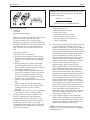
Figure 4 - Pilot Arrangements
1) JVS pilot
2) JVH pilot
3) Main burner ame pattern
The basic controls are:
a. Water temperature controls
b. Pilot safety system
c. Automatic electric gas valve(s)
d. Inducer/blower assembly (JVH )
e. Fan proving pressure switch (JVH )
f. Flue or vent damper
10. The blocked vent safety switch (JVS model only)
is used to shut the boiler down in the case of
insufcient draft due to venting system problems.
Before resetting the blocked vent safety switch
see the Appendix in Section 8D of the Installation
and Operating Instructions (Document number
1254) to ensure that all possible causes have
been investigated and corrected. If the problem
continues and the boiler cannot be restored to
normal operation call a qualied service agency.
11. The ame rollout safety switch provides
additional safety, and will shut down the
boiler should the ame from the main burners
rollout (ashback) towards the main gas valve.
Before resetting the ame rollout switch, see
Section 8D of the Installation and Operating
Instructions, (Document H2355800- for the JVS
model) to ensure that all possible causes have
been investigated and corrected. If the problem
continues and the boiler cannot be restored to
normal operation call a qualied service agency.
Never attempt to bypass the ame roll-out safety
switch for the purpose of operating the boiler.
Do not use this boiler if any part has been under
water. Immediately call a qualied service
technician to inspect the boiler and to replace any
part of the control system and any gas control
which has been under water.
12. Check all heat exchanger water connections,
ange or header gaskets for water tight integrity
24 hours after commissioning. If there are any
signs of water leakage, re-torque fasteners or re-
seat threaded connections as necessary
NOTE: The warranty does not cover any damage
caused by lack of required maintenance or improper
operating practices.
NOTE: After installation and rst start-up, check
the heat exchanger for fouling after the following
periods of operation:
24 hours 30 days
7 days 90 days+
Then once every six months thereafter.

Page 4
LAARS HEATING SYSTEMS
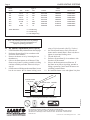
D. Air Shutter Adjustment (when required)
1. STOP! Read the safety information on the last page.
2. Perform a System Start-Up in accordance with
Section A of this manual.
3. Remove the burner cover by loosening the two
thumbscrews.
4. Observe the ame pattern on all burners. If the
ame on any burner is pulsing, unstable or lifting
continue with this procedure. Otherwise skip to
step 10.
5. On all burners exhibiting an abnormal ame, loosen
but do not remove the air shutter locking screw
using a 5/16 inch wrench. (See Fig. 5 below.)
6. On each affected burner, slowly close the air
shutter until a normal ame is observed, then re-
tighten its associated locking screw.
7. Turn the boiler off.
8. Perform a System Start-Up in accordance with
Section A of this manual.
9. Observe the ame pattern on all burners. If
the ame on any burner is pulsing, unstable or
lifting, repeat steps 5 and 6 until all burners are
exhibiting a normal ame.
10. Re-install the burner cover and tighten it in place.
LOCKING SCREW
(5/16" HEAD)
AIR SHUTTER
BURNER
Boiler Type of Valve
Model Size Sufx* Gas Part No. Mfr. No. Manufacturer
JVS 50-75 D NAT V0077400 VR8304H HONEYWELL
JVS 100-225 K NAT V0079000 VR8304H HONEYWELL
JVS 50-75 D LP V0077500 VR8304H HONEYWELL
JVS 100-225 K LP V0079100 VR8304H HONEYWELL
JVH 50-160 C NAT V2001800 SV9501H HONEYWELL
JVH 225 C NAT V2001900 SV9601H HONEYWELL
JVH 50-225 C LP V2002300 SV9501H HONEYWELL
*Sufx Denitions C = On/Off Firing
D = On/Off Firing
K = Two-Stage Firing
Figure 5 - Removing the Air Shutter Locking Screw
20 Industrial Way, Rochester, NH 03867 • 603.335.6300 • Fax 603.335.3355
1355 Kuehner Drive, Simi Valley, CA 93063 • 800.900.9276 • Fax 800.559.1583 (Sales, Service)
1869 Sismet Rd., Mississauga, Ontario, Canada LHW 1W8 • 905.238.0100 • Fax 905.366.0130
www.Laars.com
Printed in U.S.A. © Laars Heating Systems 1212 1026w
Table 1 - Gas Control Valves
Note: The warranty does not cover any damage
caused by lack of required maintenance or
improper operating procedures.
H2355700A
-
 1
1
-
 2
2
-
 3
3
-
 4
4


Ask a question and I''ll find the answer in the document
Finding information in a document is now easier with AI
in other languages
- français: Laars JVH075NCSS Mode d'emploi
Related papers
-
Laars JVH075NCSS Installation guide
-
Laars Mini-Therm JX Residential Gas-Fired Hydronic Boilers User manual
-
Laars Mighty Therm HH 1430 Installation And Operation Instructions Manual
-
-
 Laarsen Associates IW User manual
-
-
-
-
-

Other documents
-
Jackson Grills JVS-VALVE100NG Owner's manual
-
-
-
Bradford White BJVS160NDISU2 User manual
-
-
-
-
-
Bradford-White Corp BJVT User manual
-
 Smith Cast Iron Boilers GB200-S-3 User manual
