Page is loading ...

H2343000-
FOR YOUR SAFETY: This product must be installed and serviced by a professional service technician,
qualified in hot water boiler installation and maintenance. Improper installation and/or operation could
create carbon monoxide gas in flue gases which could cause serious injury, property damage, or death.
Improper installation and/or operation will void the warranty.
Installation and Operation Instructions Document 1242
WARNING
If the information in this manual is not
followed exactly, a fire or explosion may
result causing property damage, personal
injury or loss of life.
Do not store or use gasoline or other
flammable vapors and liquids in the vicinity
of this or any other appliance.
WHAT TO DO IF YOU SMELL GAS
• Do not try to light any appliance.
• Do not touch any electrical switch; do not
use any phone in your building.
• Immediately call your gas supplier from a
nearby phone. Follow the gas supplier's
instructions.
• If you cannot reach your gas supplier, call
the fire department.
Installation and service must be performed by
a qualified installer, service agency, or gas
supplier.
AVERTISSEMENT
Assurez-vous de bien suivres les instructions
données dans cette notice pour réduire au
minimum le risque d’incendie ou d’explosion ou
pour éviter tout dommage matériel, toute
blessure ou la mort.
Ne pas entreposer ni utiliser d’essence ni
d’autres vapeurs ou liquides inflammables dans
le voisinage de cet appareil ou de tout autre
appareil.
QUE FAIRE SI VOUS SENTEZ UNE ODEUR DE GAZ:
• Ne pas tenter d’allumer d’appareils.
• Ne touchez à aucun interrupteur. Ne pas vous
servir des téléphones dansle bâtiment où vous
vous trouvez.
• Appelez immédiatement votre fournisseur de
gaz depuis un voisin. Suivez les instructions
du fournisseur.
• Si vous ne pouvez rejoindre le fournisseur de
gaz, appelez le sservice des incendies.
L’installation et l’entretien doivent être assurés par
un installateur ou un service d’entretien qualifié ou
par le fournisseur de gaz.
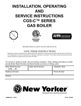
Installation and Operation
Instructions for
BRUTE MINIBRUTE MINI
BRUTE MINIBRUTE MINI
BRUTE MINI
Residential
Gas-Fired
Hydronic Boilers
Models BJVS, BJVT
Sizes 50-225
U.S. Patent No. 1,609,692
Canada Patent No. 383,318
Vent damper is optional in some provinces of Canada.
These instructions are to be stored in the packet
provided on the boiler.
238-49219-00A REV 4/11

BRADFORD WHITE CORP.
Page 2
TABLE OF CONTENTS
SECTION 1.
General Information
1.1 Introduction................................................... 3
1.2 Warranty ....................................................... 3
1.3 Codes and Standards ................................... 3
1.4 Technical Assistance.................................... 3
1.5 Materials Installer Must Provide ................... 3
1.5.1 Materials for All Installations ......................... 3
1.5.2 Materials for Most Installations ..................... 3
1.5.3 Diagnostic Tools ........................................... 4
1.6 Specifications ............................................... 4
1.6.1 General Specifications ................................. 4
1.6.2 Dimensions................................................... 4
SECTION 2.
Installation Instructions
2.1 Introduction................................................... 4
2.2 Field Assembly ............................................. 5
2.3.1 Clearances ................................................... 6
2.3.2 Flooring ........................................................ 6
SECTION 3.
Venting
3.1 Combustion Air Supply ................................. 7
3.2 Exhaust Venting ........................................... 7
3.3 Vent Pipe Sizing and General
Installation .................................................... 8
3.4 Common Venting Systems ........................... 8
3.4.1 Venting Multiple Appliances ......................... 8
3.4.2 Inspection of Commonly Vented
Appliances .................................................... 9
SECTION 4.
Gas Connections
4.1 Gas Supply and Piping ............................... 10
4.2 Special Precautions for LP Gas.................. 11
SECTION 5.
Water Connections
5.1 Water Piping ............................................... 12
5.1.1 By-pass Piping ........................................... 12
5.2 Alternate Auto-Bypass Operation ............... 12
5.3 Flow Requirements .................................... 15
5.4 Chilled Water Systems ............................... 16
5.5 Oxygen Permeable Systems ...................... 16
5.6 Anti-Freeze ................................................. 16
SECTION 6.
Electrical
6.1 General Information .................................... 16
6.2 Main Power ................................................ 16
6.3 Grounding................................................... 21
6.4 Auxiliary Devices ........................................ 21
6.4.1 Flow Switch ................................................ 21
6.4.2 Heat Anticipator .......................................... 21
SECTION 7.
Operating Instructions
7.1 Normal Operation ....................................... 21
7.2 Start-up ....................................................... 22
7.2.1 Filling the System ....................................... 22
7.2.2 Boiler Start-up ............................................ 22
7.3 Lighting and Shutdown Procedures ........... 23
7.3.1 Lighting the Boiler ....................................... 23
7.3.2 Shutdown ................................................... 24
7.3.2.1 Main Burner Shutdown (BJVT Only)............ 24
7.3.2.2 Complete Shutdown .................................... 24
7.4 High Altitude Burner
Air Shutter Adjustment................................ 24
SECTION 8.
Maintenance
8.1 General Maintenance ................................. 25
8.2 Boiler Components and Their
Operation.................................................... 26
SECTION 9.
Troubleshooting
9.1 General Boiler Troubleshooting .................. 27
9.2 Troubleshooting Guide ............................... 28
9.3 Troubleshooting Honeywell S8600
Intermittent Pilot System............................. 29
9.4 Electrical Troubleshooting .......................... 30
SECTION 10.
Glossary
10.1 Glossary of Terms ...................................... 30
SECTION 11.
Replacement Parts
11.1 Ordering Information .................................. 31
11.2 Parts List .................................................... 31
11.3 Exploded View............................................ 34

Brute Mini Hydronic Boiler
Page 3
SECTION 1.
General Information
1.1 Introduction
This manual provides information necessary for
the installation, operation, and maintenance of Model
BJV copper tube hydronic boilers.
All application and installation procedures
should be reviewed completely before proceeding with
the installation. Consult the factory, or local factory
representative, with any problems or questions
regarding this equipment. Experience has shown that
most operating problems are caused by improper
installation.
These boilers are available in two configurations;
the BJVT has a thermocouple/continuous burning pilot,
and the BJVS has an electronic intermittent ignition
device (I.I.D.). Look for the model designation on the
rating plate, which can be found on top of the boiler in
the right rear corner.
The automatic vent dampers are standard on all
U.S. and Canadian models. The side wall power
venters can be used on both BJVS and BJVT models.
Special instructions for their installation are included
in the vent damper and power venter package. Read
them carefully before installation.
1.2 Warranty
Model BJV boilers are covered by a limited
warranty. The owner should fill out the warranty
registration card and return it to .
All warranty claims must be made to an
authorized representative or directly to the factory.
Claims must include the boiler serial number and
model (this information can be found on the
rating plate), installation date, and name of the
installer. Shipping costs are not included in the
warranty coverage.
Some accessory items are shipped in separate
packages. Verify receipt of all packages listed on the
packing slip. Inspect everything for damage
immediately upon delivery, and advise the carrier of
any shortages or damage. Any such claims should be
filed with the carrier. The carrier, not the shipper, is
responsible for shortages and damage to the shipment
whether visible or concealed.
The warranty does not cover damage caused by
improper assembly installation, operation or field
modification.
1.3 Codes and Standards
The BJV Hydronic Boiler (or Brute Mini) is
design certified by CSA (Canadian Standards
Association) as complying with the latest edition of
the “Standard for Gas Fired Low Pressure Steam and
Hot Water Boilers”, ANSI Z21.13 in the USA and
CAN1-4.9 in Canada.
All boilers must be installed in accordance with
the local building and installation codes as per the
utility or authorities having jurisdiction. All local
codes take precedence over national codes.
In the absence of local codes, refer to the
following national codes for installation:
1. In the United States, the latest edition of "The
National Fuel and Gas Code", ANSI Z223.1.
Specifically, refer to Chapter 10, "Venting of
Equipment".
2. In Canada, the latest edition of "The Installation
Codes for Gas Burning appliances and
Equipment", CSA B149.1.
Any changes to the boiler, gas controls, gas
orifices, wiring, draft diverter, or improper installation
may void the warranty. If change is required to any of
the above, consult the factory.
1.4 Technical Assistance
Consult Bradford White or your local factory
representative with any questions or problems
involving the specifications, installation, and operation
of your equipment. An experienced technical support
staff is ready to assist you in assuring the proper
performance and application of products. For
technical support call the Bradford White Technical
Service Department.
1.5 Materials Installer Must Provide
1.5.1 Materials for All Installations
The following items are needed and are to be
supplied by the installer for all Brute Mini boiler
installations:
1. The correct size gas pipe to supply the gas to the
boiler (see Section 4.1 for correct gas pipe size).
2. A CSA listed manually operated gas valve to be
installed in the gas line outside of the boiler
jacket.
3. A suitable gas union joint or other removable
connector to connect the boiler to the gas line
outside of the boiler.
4. Plumbing items needed to provide a sediment
trap (drip leg) in the gas line between the manual
gas valve and the union to the boiler.
5. A 115 VAC power supply. A junction box is not
needed at the boiler, connections are made inside
of the boiler’s control panel (see Figure 8).
6. Vent pipe of the same or larger diameter as the
vent damper or draft diverter outlet (see Section
3.3 for venting instructions).
1.5.2 Materials for Most Installations
In addition to the items listed above, the
following items may be needed:
1. Plumbing materials for the bypass piping, which
is required for:
a. Any system where the return water

BRADFORD WHITE CORP.
Page 4
temperature may be less than 120°F, such
as in-floor radiant systems, snow melt
systems or other systems where a “cold
start” is expected frequently due to
thermostat setbacks, etc. See Figure 11.
b. Any system where the temperature rise
across the heat exchanger is above 30°F
(see Section 5 and Figure 7).
2. Combustion air grates for openings sized in
accordance with Section 3.1.
3. Field interlock wiring for any motorized
combustion air louvers to ensure the boiler does
not fire if motorized louvers do not open.
4. A suitable non-combustible base if installed on a
combustible floor (see Section 2.3.2)
1.5.3 Diagnostic Tools
The following materials are needed to verify
correct installation:
1. Gas manometer to verify gas pressure
2. Strap-on, digital or infrared thermometer to
check temperature rise across the heat exchanger.
3. Suggested: Draft gauge and combustion test
equipment.
1.6 Specifications
1.6.1 General Specifications
1. Installation Location:
Certified for use in Indoor Applications only
2. Minimum Clearance From Combustible
Material:
See Table 1 in Section 2.3.1.
3. Supply Gas Type:
Certified for use with Natural Gas and LP Gas
4. Gas Pipe/Boiler Gas Valve Connection:
Nat LP
50-225 ½" NPT ½" NPT
5. Inlet Gas Supply Pressure:
Minimum Maximum
Natural Gas: 5.5" WC 10.5" WC
LP Gas: 10.0" WC 13.0" WC
6. Water Pipe/Boiler Connection:
1¼" NPT
7. Water Flow Rate:
See Table in Section 5.2
8. Pressure Relief Valve:
30 PSI
9. Recommended system pressure:
12 PSI
10. Exhaust Vent Connection Size:
50 4" Diameter
75-100 5" Diameter
125-160 6" Diameter
225 7" Diameter
11. Electrical Supply:
115 Volts AC
12. Modification of Boiler for High Altitude:
Brute Mini Boilers are normally shipped from the
factory in the low altitude (sea level) operational
configuration. When requested, the boilers can be
configured and shipped for higher altitudes. For
field conversions to change altitude
configurations, conversion parts are available
from. For more information or call the Customer
Service Department.
1.6.2 Dimensions
See Figure 1 for a diagram showing the boiler’s
exterior dimensions and dimensions to critical
connections on the boiler.
SECTION 2.
Installation Instructions
2.1 Introduction
WARNING
Improper installation or maintenance can cause
nausea or asphyxiation from carbon monoxide in
flue gases which could result in severe injury, or
death.
AVERTISSEMENT
Une installation ou un entretien in adéquat peut
causer la nausée ou l’asphyxie en raison du
monoxyde de carbone présent dans les gaz de
combustion et même entrainer des blessures
graves ou la mort.
Install the Brute Mini boilers and vent dampers in
accordance with the procedures in this manual, local
codes and ordinances, and in accordance with the
latest edition of the appropriate national code (see
Section 1.3 “Codes and Standards”).
All gas-fired products require correct installation
to assure safe operation. The requirements for boilers
include the following:
1. Field assembly
2. Appropriate site location (clearances) and
flooring
3. Sufficient combustion and ventilation air
4. Properly sized gas meter and piping
5. Proper electrical wiring (if required)
6. Adequate water flow
This manual provides the information needed to
meet these requirements. Review all application and
installation procedures completely before continuing
the installation.
NOTE: The Brute Mini boiler is approved for indoor
installation only.

Brute Mini Hydronic Boiler
Page 5
2.2 Field Assembly
1. Brute Mini boilers have built-in draft diverter for
natural draft operation.
2. Find the vent damper box which is located in the
boiler package.
3. Install the vent damper directly to the top of the
draft diverter outlet with the damper operator
facing to the front of the boiler, and with the flow
direction arrow pointing upward. Use the vent
damper wire harness provided with the boiler to
connect the vent damper to the boiler. The
bracket end of the harness should be connected
to the vent damper actuator.
4. For Model BJVS only: Install the metal plug
provided with the vent damper onto the damper
plate hole. Disregard the metal plug in case of
standing (continuous) pilot boilers. For all
BJVT models, the damper plate hole should
never be blocked.
5. Do not modify the automatic vent damper
device. It is very important that no other vents
are closed. Provide at least six inches clearance
between the automatic vent damper and
combustible construction, and be sure to allow
access for servicing the damper.
6. Install the temperature/pressure gauge provided
in the parts box.
Figure 1. Dimensional Information.
Dimensions in inches cm
Dimensions
Water Gas
inches cm
Conn. Conn.
Size* A B C D E V
in. in.
50 13-3/8 34 27-3/4 71 23-5/8 60 21-3/4 55 26-1/2 67 4 10 1-1/4 1/2
75 13-3/8 34 27-3/4 71 24-1/8 61 21-3/4 55 27-1/2 70 5 13 1-1/4 1/2
100 16-7/8 43 28-3/4 73 24-1/8 61 22-3/4 58 27-1/2 70 5 13 1-1/4 1/2
125 16-7/8 43 28-3/4 73 23-5/8 60 22-3/4 58 27-1/2 70 6 15 1-1/4 1/2
160 20-3/8 52 28-3/4 73 23-5/8 60 22-3/4 58 27-1/2 70 6 15 1-1/4 1/2
225 25-5/8 65 31-1/2 80 23-1/4 59 23-3/4 63 27-1/2 70 7 18 1-1/4 *3/4**
* Values shown are for both BJVS and BJVT Models **1/2 for propane
Figure 2. Field Assembly Items.

BRADFORD WHITE CORP.
Page 6
Caution
Do not force motor operation when operator is
fastened to the damper by moving the damper
blade, turning the shaft or by turning the position
indicator.
Attention
Ne pas tourner le registre manuellement avec ou
sans courant électrique ou le moteur sera
endommagé.
2.3.1 Clearances
The boiler must be placed to provide clearances
on all sides for maintenance and inspection. There
must also be minimum distances maintained from
2.3.2 Flooring
The boiler shall be installed on a level floor of
noncombustible construction or on fire-resistant slabs
or arches. Noncombustible flooring is defined as
flooring material and surface finish not capable of
being ignited and burning and with no combustible
materials against the underside. Acceptable materials
are those consisting entirely of a combination of steel,
iron, brick, tile, concrete, slate, glass or plaster. Do
not install the heater directly on a combustible wood
or carpet floor without placing a noncombustible
platform between the floor and the heater.
The boiler can be installed on a combustible
floor if a noncombustible base assembly, available
from , is used. See the boiler rating plate or the Parts
List (Section 11) of this manual for the appropriate
base part number. Boilers must never be installed
directly on carpeting.
As an alternative to the noncombustible base
plate, in the United States, the National Fuel Gas Code
allows a heater to be placed on a combustible surface
when there is a platform under the heater made of
hollow masonry no less than 4 inches (102 millimeters
[mm]) thick, covered with sheet metal at least 24
gauge thick and extending beyond the full width and
depth of the heater by at least 12 inches (305mm) in
all directions. The masonry must be laid with ends
unsealed, and joints matched to provide free
circulation of air from side to side through the
masonry (see Figure 4). If the boiler is installed in a
carpeted alcove, the entire floor of the alcove must be
covered by a noncombustible platform.
Note: Clearances listed in Table 1 are manufacturer’s tested values.
These are given as minimum values. Where local and national codes
apply, and values are different than those listed in Table 1, use the
greater value to ensure safe operation.
Table 1. Minimum Boiler Clearances
From Combustible Surfaces.
Dégagements Minimaux à Assurer Entre Ics Parois de
L’appareil et leo Constructions Combustibles
Boiler Sizes 50-125 160-225
Clearances in cm in cm
Left side 6 15 6 15
Right side 6 15 6 15
Rear 6 15 6 15
Front 4 10 6 15
Flue 6 15 6 15
Top 23 48 36 91
combustible surfaces (see Table 1).
At least 15" (381mm) access must be available
in front of the boiler for burner removal. Consult local
codes for clearances to hot water pipes and
accessories.
If the boiler is to be installed in a garage, all
burners and burner ignition devices must have a
minimum 18" (457mm) clearance above the floor.
The Model BJV-50 through BJV-100 boilers can
be installed in a closet, as long as the minimum
clearances shown in Table 1 and Figure 3 are
observed. Special attention should be paid to
clearances between the front of the boiler and the
closet door when it is closed.
Consult the American National Standard Z21.13
for more information concerning closet installations.
In Canada, refer to the latest edition of CSA-B149.1.
Figure 3. Closet and Alcove Installation (see Table 3).
Dimensions in inches cm.
6 15
6 15
6 15
4*
10
*6" for models BJV160 to BJV225.
Figure 4. Typical Combustible Floor Installation.

Brute Mini Hydronic Boiler
Page 7
SECTION 3.
Venting
3.1 Combustion Air Supply
The boiler location must provide sufficient
air supply for proper combustion, and ventilation
of the surrounding area as outlined in the latest
edition of ANSI standard Z223.1 or in Canada,
CSA-B149.1, and any local codes that may be
applicable.
In general, these requirements specify that boiler
rooms which represent confined spaces should be
provided with two permanent air supply openings; one
within 12 inches (305mm) of the ceiling, the other
within 12 inches (305mm) of the floor (see Table 2).
Inside Air Supply: When combustion is
supplied from inside the building, each opening should
have a minimum free area of one square inch per 1,000
BTU/h (0.3kW) input of the total input rating of all
appliances in the enclosed area. These openings
should never be less than 100 square inches
(645 sq. cm).
Note: In Canada, follow Canadian Standard, CSA-
B149.1 or local codes.
Exhaust Fans or Vents: Any equipment which
exhausts air from the boiler room can deplete the
combustion air supply or reverse the natural draft
action of the venting system. This could cause flue
products to accumulate in the boiler room. Additional
air must be supplied to compensate for such exhaust.
The information in Table 2 is not applicable in
installations where exhaust fans or blowers of any
type are used. Such installations must be designed by
qualified engineers.
If a blower or fan is used to supply air to the
boiler room, the installer should make sure it does not
create drafts which could cause nuisance shutdowns of
the pilot. If a blower is necessary to provide adequate
combustion air to the boiler, a suitable switch or
equivalent must be wired into the boiler control circuit
to prevent the boiler from firing unless the blower is
operating.
The boiler must be completely isolated and
protected from any source of corrosive chemical
fumes such as those emitted by trichlorethylene,
perchlorethylene, chlorine, etc.
WARNING
Do not store any chemical, cleaners, or other
corrosive material near combustion air openings or
in the room. Avoid locating dryer vents in the vicinity
of combustion air openings. Failure to prevent
corrosive materials from mixing with combustion air
can result in reduced boiler life and unsafe boiler
operation.
AVERTISSEMENT
N’entrepposer aucun produit chimique, produit
nettoyant ou produit corrosif à proximité des
bouches d’air de combustion ou dans la pièce.
Éviter de placer des tuyaux de ventilation pour
sécheuse à proximité des bouches d’air de
combustion. Le fait de laisser des maitières
corrosives se mélanger à l’air de combustion risque
de réduire le cycle de vie de l’appareil de chauffage
et de compromettre son fonctionnement.
3.2 Exhaust Venting
Vent piping must be of the same or larger
diameter as the vent damper or draft diverter outlet.
The only correct procedure for vent pipe sizing is to
do so in accordance with Table 3 and the applicable
installation code as stated in the following warning.
Boiler Size
Outside Air
Area in Sq. In.*
Inside Air
Area in Sq. In.* (sq cm)
50 15
97
100 645
75 20
129
100 645
100 25
161
100 645
125 32
206
125 807
160 40
258
160 1032
225 60
387
225 1452
*Area indicated is for one of two openings; one at floor level and
one at the ceiling, so the total net free area would be double the
figures indicated. For special conditions, refer to NFPA54 ANSI
Z223.1. In Canada refer to the National Standard CSA B149.1
which differs from this table.
NOTE: Check with louver manufacturers for Net Free Area of
louvers. Correct for screen resistance to the Net Free Area if a
screen is installed. Check all local codes applicable to
combustion air.
Table 2. Minimum Recommended
Air Supply to Boiler Room.
Outside Air Area*
Sq. In. sq cm
Inside Air Area*
Sq. In. sq cm
Important: See gas piping selection chart, Table 3 for
gas line sizing. In all cases, pipe size is larger than inlet
connection on heater. Run pipe size shown in chart and
reduce at heater inlet.
Outside Air Supply: When combustion air is
supplied directly through an outside wall, each opening
should have a minimum free area of one square inch per
4,000 BTU/h (1.2kW) input of the total input rating of
all appliances in the enclosed area.
If air is provided through horizontal ducts,
each opening and duct must provide one square inch
of flow area for each 2000 BTU/h (0.6 kW). These
requirements are summarized in Table 2. Note that
the required size of openings shall be based on the
net free area of each opening. Where the free area
of louver or grille is known it shall be used in
calculating the effective free area. Where the free
area are not known, it shall be assumed that wood
louvers will have 25 percent free area, and metal
louvers and grilles will have 75 percent free area.

BRADFORD WHITE CORP.
Page 8
WARNING
Vent pipe diameter must be as required by the
National fuel Gas Code Z223.1 or the Canadian
Installation Codes for Gas Appliances CSA-B149.1.
Undersize pipe can result in inadequate venting
and oversize pipe can result in vent condensation.
In either case the result can be release of
combustion products to the indoors. This can cause
serious injury or death by carbon monoxide
poisoning or asphyxiation.
AVERTISSEMENT
Le diamètre des tuyaux de ventilation doit répondre
aux exigences du National Fuel Gas Code Z223.1
ou du code canadien des installations des appareils
à gaz CSA B149.1. Des tuyaux trop petits rispquent
d’entraîner une ventilation inadéquate et des tuyaux
trop gros risquent de provoquer une condensation
dans les tuyaux. Dans un cas comme dans l’autre,
des produits de combustion risquent de s’échapper
dans le bâtiment et causer des blessures graves ou
l’asphyxie par le monoxyde de carbone.
Do not weld or fasten the vent pipe to the boiler
draft diverter. The weight of the stack must not rest on
the boiler.
The draft diverter and boiler top must be
easily removable for normal boiler service and
inspection.
Avoid horizontal runs of the vent pipe, and 90°
elbows, reductions and restrictions. Horizontal runs
should have at least a 1/4" rise per foot (20mm per
meter) in the direction of flow. A vent connector shall
be supported for the design and weight of the material
employed to maintain clearances and prevent physical
damage and separation of joints.
Avoid terminating boiler vents near air
conditioning or air supply fans. The fans can pick up
exhaust flue products from the boiler and return them
inside the building, creating a possible health hazard.
Do not located the vent terminal where flue products
could strike against building materials and cause
degradation.
Always use double-wall or insulated vent pipe
when used as a chimney (Type B or equivalent). In
cold weather, uninsulated outside vents can chill the
rising flue products, blocking the natural draft action
of the venting system. This can create a health hazard
by spilling flue products into the boiler room. Use
engineered venting tables acceptable to the authority
having jurisdiction to size the venting pipe or liner.
Avoid oversize vent piping or extremely long
runs of the pipe which may cause excessive cooling
and condensation.
Before connecting a vent connector to a
chimney, the chimney passageway shall be examined
to ascertain that it is clear and free of obstructions.
When inspection reveals that an existing chimney is
not safe for the intended application, it shall be rebuilt
to conform to nationally recognized standards (see
National Building Code or ANSI/NFPA 211), lined or
relined with a suitable liner, or replaced with a vent or
chimney suitable for the equipment to be attached.
3.4 Common Venting Systems
3.4.1 Venting Multiple Appliances
When common venting BJVS or BJVT natural
draft boilers with other appliances through one shared
duct called a “common vent”, special care must be
taken by the installer to ensure safe operation. In the
event that the common vent is blocked, it is possible,
especially for fan-assisted devices, to vent backwards
through non-operating appliances sharing the vent,
allowing combustion products to infiltrate occupied
spaces. If the appliances are allowed to operate in
this condition, serious injury or death may occur.
BJVS/BJVT Vent Pipe Diameter
Size inch cm
50 4 10
75 5 13
100 5 13
125 6 15
160 6 15
225 7 18
Table 3. Exhaust Vent Connection Size.
3.3 Vent Pipe Sizing and General
Installation
All vent installations and boiler stacking must be
designed and installed in accordance with all local,
state or provincial codes and with:
1. Chapter 7, “Venting of Equipment” of the
national Fuel Gas Code, ANSI 223.1 latest
edition, or the applicable provisions of the local
building codes.
2. In Canada, CSA-B149.1.
The draft diverter outlet is to be connected to an
unobstructed vent pipe of the same or larger diameter,
terminating outside the building. The vent pipe must
have a listed vent cap and extend at least two feet
above any object with a ten foot radius. All
connections should be made with rustproof sheet
metal screws.
IMPORTANT NOTE: Do not use sheet metal screws
at the snap lock joints of Type B gas vents.

Brute Mini Hydronic Boiler
Page 9
WARNING
Operation of appliances with a blocked common
vent may lead to serious injury or death. Safety
devices must be implemented to prevent blocked
common vent operation. If safe operation of all
appliances connected to a common vent cannot be
assured, including prevention of spillage of flue
gasses into living spaces, common venting should
not be applied, and appliances should each be
vented separately.
AVERTISSEMENT
Le fonctionnement des appareils avec un système
d’évacuation bloqué peut provoquer des blessures
graves, voire la mort. Des dispositifs de sécurité
doivent être installés pour éviter le blocage des
systèmes d’évacuation. Si le fonctionnement de
tous les appareils connectés à un système
d’évacuation commun ne peut pas être assuré, y
compris la prévention de la dispersion des gaz
toxiques dans les espaces habités, on ne devrait
pas installer un système d’évacuation commun et
chaque appareil devrait être ventilé séparément.
It is for this reason that, in addition to following
proper vent sizing, construction and safety
requirements from the National Fuel Gas Code, ANSI
Z223.1 or in Canada, from CSA B149.1 as well as all
applicable local codes, it is required that installers
provide some means to prevent operation with a
blocked common vent. It is suggested that a blocked
vent safety system be employed such that if the switch
from one appliance trips due to excessive stack spill or
backpressure indicating a blocked vent condition, that
all appliances attached to the vent be locked out and
prevented from operating. As an additional precaution,
it is recommended that a Carbon Monoxide (CO)
alarm be installed in all enclosed spaces containing
combustion appliances. If assistance is required in
determining how a blocked vent safety system should
be connected to a product, please call Applications
Engineering (see back cover for info).
Refer to the installation and operating
instructions on all appliances to be common vented for
instructions, warnings, restrictions and safety
requirements. If safe operation of all appliances
connected to a common vent cannot be assured,
including prevention of spillage of flue gasses into
living spaces, common venting should not be applied,
and appliances should each be vented separately.
3.4.2 Inspection of Commonly Vented
Appliances
If the instrumentation of this boiler replaces an
older boiler in a common vent system with other
appliances, or if you remove additional appliances
from the common vent, all the appliances must be
checked for proper venting.
At the time of removal of an existing boiler, the
following steps shall be followed with each appliance
remaining connected to the common venting system
placed in operation, while the other appliances
remaining connected to the common venting system
are not in operation.
1. Seal any unused openings in the common
venting system.
Sceller toutes les ouvertures non utilisées du
système d’évacuation.
2. Visually inspect the venting system for proper
size and horizontal pitch and determine there is
no blockage or restriction, leakage, corrosion and
other deficiencies which could cause an unsafe
condition.
Inspecter de façon visuelle le système
d’évacuation pour déterminer la grosseur et
l’inclinaison horizontale qui conviennent et
s’assurer que le système est exampt
d’obstruction, d’étranglement, de fuite, de
corrosion et autres défaillances qui pourraient
présenter des risques.
3. Insofar as it is practical, close all building doors
and windows and all doors between the space in
which the appliances remaining connected to the
common venting system are located and other
spaces of the building. Turn on clothes dryers
and any appliance not connected to the common
venting system. Turn on any exhaust fans, such
as range hoods and bathroom exhausts, so they
will operate at maximum speed. Do not operate a
summer exhaust fan. Close fireplace dampers.
Dans la mesure du possible, fermer toutes les
portes et les fenêtres du bâtiment et toutes les
portes entre l’espace où les appareils toujours
raccordés au système d’évacuation sont installés
et les autres espaces du bùtiment. Mettre en
marche les sécheuses, tous les appareils non
raccordés au systéme d’évacuation commun et
tous les ventilateurs d’extraction comme les
hottes de cuisinière et les ventilateurs des salles
de bain. S’assurer que ces ventilateurs
fonctionnent à la vitesse maximale. Ne pas faire
fonctionner les ventilateurs d’été. Fermer les
registres des cheminées.
4. Place in operation the appliance being inspected.
Follow the lighting instructions. Adjust
thermostat so appliance will operate
continuously.
Mettre l’appareil inspecté en marche. Suivre les
instructions d’allumage. Régler le thermostat de
façon que l’appareil fonctionne de façon
continue.
5. Test for spillage at the draft hood relief opening
after 5 minutes of main burner operation. Use the

BRADFORD WHITE CORP.
Page 10
SECTION 4.
Gas Connections
4.1 Gas Supply and Piping
Review the following general instructions before
continuing the installation.
WARNING
The Brute Mini BJVS and BJVT boilers are designed
for use with either natural gas or LP gas. Check the
rating plate to be sure that the boiler is designed to
use the type of gas being supplied. DO NOT
ATTEMPT TO CONVERT THIS HEATER FOR
USE WITH ANY OTHER TYPE OF FUEL.
AVERTISSEMENT
Les appareils de chauffage à faibles sont conçus
pour être utillsés avec du gaz naturel ou du gaz de
pétrole liquéfié (GPL). Vérifiez l’information inscrite
sur la plaque signalétique du pour vous assurer que
l’appareil est conçu pour le type de gaz fourni. NE
PAS ESSAYER DE CONVERTIR CET APPAREIL
À UN AUTRE TYPE DE GAZ.\
1. Gas piping installation must be in accordance
with the latest edition of ANSI Z223.1 and all
local codes. In Canada, the installation must be
in accordance with CSA-B149.1 and all local
codes that apply.
2. Check the gas supply to be sure that it is the
same as the gas indicated on the boiler’s plate.
Brute Mini BJVS and BJVT boilers, as shipped
from the factory, are certified to operate within
the altitude range indicated on the rating plate. If
a field conversion to a different altitude range
should be necessary, conversion parts are
available for changing the altitude range of the
heater. Contact factory for parts information.
Caution
Permanent damage to the gas valve will occur if the
following procedures are not followed.
Attention
Vous endommagerez la soupape de gaz si vous ne
respectez pas les procédures suivantes.
3. Use the figures in Table 4 to size the gas inlet
piping from the gas meter to the heater. Check all
local codes for compliance before installing the
heater.
flame of a match or candle, or smoke from a
cigarette, cigar or pipe.
Faire fonctionner le brûleur principal pendant 5
min ensuite, déterminer si le coupe-tirage
déborde à l’ouverture de décharge. Utiliser la
flamme d’une allumette ou d’une chandelle ou la
fumée d’une cigarette, d’une cigare ou d’une
pipe.
6. After it has been determined that each appliance
remaining connected to the common venting
system properly vents when tested as outlined
above, return doors, windows, exhaust fans,
fireplace dampers and any other gas burning
appliance to their previous conditions of use.
Une fois qu’il a été déterminé, selon la méthode
inidquée ci-dessus, que chaque appareil raccordé
au système d’évacuation est mis à l’air libre de
façon adéquate. Remettre les portes et les
fenêtres, les ventilateurs, les registres de
cheminées et les appareils au gaz à leur position
originale.
7. Any improper operation of the common venting
system should be corrected so the installation
conforms with the National Fuel Gas Code,
ANSI Z223.1. When resizing any portion of the
common venting system, the common venting
system should be resized to approach the
minimum size as determined using the
appropriate tables in Appendix G in the National
Fuel Gas Code, ANSI Z223.1.
Tout mauvais fonctionnement du système
d’évacuation commun devrait être corrigé de
façon que l’installation soit conforme au national
Fuel Gas Code, ANSI Z223.1 et (ou) aux codes
d}installation CSA-B149.1. Si la grosseur d’une
section du système d’évacuation doit être
modifiée, le système devrait être modifié pour
respecter les valeurs minimales des tableaux
pertinents de l’appendices F du National Fuel
Gas Code, ANSI Z2231.1 et (ou) des codes
d}installation CSA-B149.1.

Brute Mini Hydronic Boiler
Page 11
NOTE: The boiler and all other gas appliances
sharing the boiler gas supply line must be firing at
maximum capacity to properly measure the inlet
supply pressure. Low gas pressure could be an
indication of an undersize gas meter and/or
obstructed gas supply line.
8. The correct high fire burner manifold gas
pressure is stamped on the rating plate. The
regulator is pre-set at the factory, and normally
requires no further adjustment. For two-stage
units (BJVS 100-225) be sure unit is able to fire
at both high and low fire.
9. Before operating the boiler, the complete gas
supply system and all connections must be tested
for leaks using a leak detector solution. Do not
use an open flame.
Caution
Some leak test solutions (including soap and water)
may cause corrosion or stress cracking. Rinse the
piping with water after testing.
Attention
Certaines solultions d’essai d’étanchéité (y compris
l’eau et le savon) peuvent causer de la corrosion ou
de la fissuration. Rincez les tuyaux à l’eau apprès
l’essai d’étanchéité.
4.2 Special Precautions for LP Gas
LP Gas is heavier than air and can therefore
more readily collect or “pool” in enclosed areas if
provision for proper ventilation is not made. Be sure
to pay special attention to proper ventilation for LP
gas. Locate boilers a safe distance from LP gas
cylinders and filling equipment. In the United States,
consult the “National Fuel Gas Code” (NFPA 54 /
ANSI Z223.1, latest edition) or in Canada, the
Propane Installation Code (CSA-B149.1), any local
codes and fire protection authorities about specific
installation restrictions in your area.
4. A sediment trap (drip leg) must be installed
ahead of the gas controls (see Figure 5). Fit the
trap with a threaded cap which can be removed
for cleaning.
5. Install a manual gas shutoff valve for service and
safety. Do not use a restrictive gas cock. Flexible
gas connectors, if used, must be CSA rated for
the total input rating of the boiler.
6. Disconnect the boiler and its individual shutoff
valve from the gas supply system during pressure
testing of the system at pressures higher than 1/2
pounds per square inch (psi) (3.45 kilopascals
[kPa]). If the test pressure is equal to or less than
1/2 psi (3.45 kPa), close the manual shutoff
valve on the heater during the piping pressure
test.
7. If the gas supply pressure is less than required,
check for undersized pipe between the meter and
the boiler, a restrictive fitting, or an undersized
gas meter. Gas supply pressures to the heater are
listed in Table 5.
NOTE: The maximum inlet gas pressure must not
exceed the specified value. The minimum value
listed is for the purpose of input adjustment. Refer
to Table 5.
Distance
From Gas
Meter
Boiler Size
50 75 100 125 160 225
Pipe Size
0-50'
1/2 3/4 3/4 3/4 1 1
0-15m
50-100'
3/4 3/4 3/4 1 1 1-1/4
15-30m
100-200'
3/4 1 1 1 1-1/4 1-1/4
30-60m
Table 4. Natural Gas Pipe Size Requirements*
*Note: These figures are for Natural Gas (.65 Sp. Gr.), and are
based on 1/2" water column pressure drop. Check supply
pressure with a manometer, and local code requirements for
variations. For LPG, reduce pipe diameter one size, but
maintain a 1/2" minimum diameter. A 'normal' number of Tees
and elbows have been taken into allowance.
Figure 5. Typical design for a sediment trap/drip leg.
Supply Pressure Minimum Maximum
Natural Gas 5.5 Inches WC 10.5 Inches WC
(1.3 kPa) (2.5 kPa)
LP Gas 10.0 Inches WC 13.0 Inches WC
(2.4 kPa) (3.1 kPa)
Table 5. Gas Supply Pressure Requirements.
Gas Supply
Inlet
Tee
Fitting
3 in.
(76mm) Min.
Cap
Nipple
To Equipment
Inlet

BRADFORD WHITE CORP.
Page 12
A full sized, 1¼" bypass with balancing valves is
strongly recommended for all systems, and required
when: 1) the boiler is installed without primary-
secondary piping in a multiple zone system; 2) when
the return water temperature can be expected to be
lower than 120°F (44°C); or 3) whenever the system
piping on the outlet side of the boiler may allow
reduced flow through the heat exchanger, causing
excessive temperature rise (see Section 5.2).
Note: Bradford White strongly recommends a
primary/secondary piping system for all installations,
especially sizes 125, 160 and 225. In this system, a
circulator is dedicated to pumping the boiler only. This
circulator should be sized for the boiler head loss and
flow rate.
All precautions must be taken by the installer to
insure that a maximum temperature rise through the
boiler does not exceed 30°F (17°C). The temperature
rise on boilers installed in multi-zone systems using
zone valves must be taken when the zone of the
longest length and/or the zone of the highest head loss
is open.
A full size, 1¼" diameter by-pass with
balancing valve must be installed if a return water
temperature below 120°F (44°C) is expected under
operating conditions regardless of boiler size. This
may be expected in many systems, including in-
floor radiant and snow melt systems.
Adjusting the bypass:
Refer to figure 7. Provide a means of measuring
temperature on the inlet pipe to the boiler such as
using a strap on or infrared themometer. Starting with
both balancing valves fully open, start the boiler.
Adjust the balancing valve on the return to the system
slowly to provide 120°F (44°C) water at the inlet to
the boiler, leaving the bypass balancing valve fully
open. As the system warms up, this valve may need to
be adjusted open. In rare cases, this valve will have to
be kept fully open, and the bypass balancing valve
adjusted toward closed to prevent heated bypass water
from satisfying the call for heat when the system is up
to temperature.
5.2 Alternate Auto-Bypass Operation
Use of the themostatic union, p/n 2400-030, can
provide automatic bypass operation in primary -
secondary piped systems (but cannot be used when
primary - secondary piping is not used). The
thermostatic union is installed on the outlet piping,
after the bypass assembly. It can be used in place of a
balancing valve. It opens fully at 140°F (see Figure 6).
Contact the factory for more information.
SECTION 5.
Water Connections
5.1 Water Piping
Figure 6 shows ‘typical’ plumbing installations.
Be sure to provide unions and isolation valves at the
boiler inlet and outlet so it can be isolated for service.
Check local codes for specific plumbing requirements
before beginning the installation.
An ASME pressure relief valve is supplied on all
BJV boilers, and is pre-set at 30 PSI. The valve outlet
piping must discharge to a drain. Under no
circumstances should the relief valve piping be a
closed circuit.
A pressure reducing valve (automatic feed) must
be used to maintain system at constant proper pressure
(see Figure 6). Supply properly installed purge valves
to eliminate air from each circuit.
A drain valve is supplied with the boiler, and can
be found in the plastic bag shipped with each boiler.
This valve is to be installed on the lower right side of
the boiler, see Figure 1, and is used for draining the
unit. To drain the boiler completely, open the drain
valve and remove the two drain plugs located on
the lower left side of the boiler.
Be sure to include air vent devices located at the
highest point in the system to eliminate trapped air,
and an air elimination device near the outlet side of
the BJV boiler. Manual vent valves are recommended.
Hot water piping should be supported by suitable
hangers or floor stands, NOT by the boiler. Due to
expansion and contraction of copper pipe,
consideration should be given to the type of hangers
used. Rigid hangers could transmit noise through the
system caused by the piping sliding in the hangers. It
is recommended that padding be used when rigid
hangers are installed.
Gas piping should also be supported by suitable
hangers or floor stands, not the boiler.
A properly sized expansion tank must be
included in the system. offers an aircharged
diaphragm-type expansion tank, with an automatic
feed valve, which includes a pressure regulator set at
12 psig. The part numbers are:
Less Than 20 Gallons in System A0066800
20 to 45 Gallons in System A0066900
5.1.1 By-pass Piping
The following information and suggestions are
made on by-pass piping as it affects the temperature
rise at the boiler. A boiler temperature rise must be
taken on all BJV boiler installations. If the temperature
rise exceeds 30°F (17°C) at full rate, it is an indication
that the boiler is not receiving adequate water flow.
Check the pump for any obstruction, replace the pump
with a larger size where necessary, or install a system
by-pass as indicated in Figures 6 and 7.

Brute Mini Hydronic Boiler
Page 13
Figure 6. Typical Plumbing Installations.

BRADFORD WHITE CORP.
Page 14
Figure 6A. Typical Plumbing Installations.
System
Loop
Expansion
Tank
PumpAir Scoop
Feed
Water
Single Circuit System
Multi-Zone
Valve System
Multi-Zone
Pump
System
Figure 6B. Typical Plumbing Installations.
BJV
Boiler
BJV
Boiler
BJV
Boiler

Brute Mini Hydronic Boiler
Page 15
5.3 Flow Requirements
All high recovery, low volume water boilers must
have adequate flow for efficient operation. Pump
selection is critical to this goal, and pumps should be
selected to provide for system design water
temperature rise. Table 6 details temperature rise and
water flow (GPM) for the Brute Mini boilers.
Damage from improper flow is not warranted.
Failure to insure proper water flow through the
heat exchanger of the boiler will void the warranty.
Flow can be verified by measuring the difference in
water temperatures between the boiler inlet and outlet.
For example: For a BJV-100 installation, the inlet
water temperature is 160°F (71°C), and the outlet
temperature is 180°F (82°C) at Normal Input Rate
from the rating plate. That means there is a 20° (11°C)
temperature rise through the boiler. According to
Table 1, that would indicate a flow rate of 8 GPM
(0.5L/S). Temperature rise must be measured with the
longest (highest head) zone calling for heat alone.
Other factors to be considered before selecting a
pump are pipe size, the number of fittings throughout
the system, smoothness of the interior surface of the
pipe, the quantity of water flowing through the pipe,
whether a glycol solution is being used, and the total
length of piping in the system. Table 7 provides
examle pump selection criteria using Type L copper
piping, one zone valve and up to eight elbows for
single zone systems. Consult the factory or a qualified
system designer if you have more fittings, different
size or type of pipe (especially in retrofit situations),
or some other unique system configuraiton not
illustrated in this manual.
Figure 7. By-pass Piping.
Balancing Valve
or optional
thermostatic union,
P/N 2400-030.
(Primary/Secondary
only)
To
System
From
System
In
(Return)
Out
(Supply)
Drip
Leg
Left Side View
A full size by-pass must be installed.
*A circulator and/or primary/secondary piping are required. Consult
factory.
1. Chart is based on 30°F (17°C) maximum temperature rise.
2. Calculations are based on Type L copper tubing with one
zone valve and eight elbows.
3. Typical circulating pumps:
1
/
25
HP=Taco 007, B&G LR-20 or
SLC-25, Grundfos UP15-42F, or equivalent.
1
/
12
HP=B&G LR-
12, Grundfos UP26-42F, or equivalent.
1
/
6
HP=B&G series
HV, Grundfos UP43-75, or equivalent.
Table 7. Maximum Suggested Circuit Length in Feet.
Table 6. Temperature Rise °F °C.
gpm = Water Flow in gallons per minute. l/s = Water flow in liters per second.
ft = Pressure drop (headloss) through the boiler in feet of water. m = Pressure drop (headloss) through the boiler in meters of water.
Notes: 1. Shaded area is the recommended flow and temperature rise.
2. Temperature rise and associated flow rates are based on high fire operation at the Normal Input Rate from the rating plate.
Balancing
Valve
15°F 8°C 20°F 11°C 25°F 14°C
Size Flow Rate Headloss Flow Rate Headloss Flow Rate Headloss
gpm l/s ft m gpm l/s ft m gpm l/s ft m
50 5.3 0.3 0.3 0.1 4 0.3 0.2 0.1 3.2 0.2 0.1 0
75 8 0.5 0.6 0.2 6 0.4 0.3 0.1 4.8 0.3 0.2 0.1
100 10.7 0.7 1.3 0.4 8 0.5 0.7 0.2 6.4 0.4 0.5 0.2
125 13.3 0.8 2.2 0.7 10 0.6 1.3 0.4 8 0.5 0.8 0.2
160 17 1.1 2.5 0.8 12.8 0.8 1.8 0.5 10.2 0.6 1.2 0.4
225 24 1.5 5 1.5 18 1.1 3.1 0.9 14.4 0.9 1.9 0.6
1/2" Pipe 3/4" Pipe 1" Pipe 1-1/4" Pipe
Size Pump Pump Pump Pump
H.P. H.P. H.P. H.P.
1/25 1/12 1/25 1/12 1/6 1/25 1/12 1/6 1/25 1/12 1/6
50 50 99 390 680
*** * ***
75
*
35 160 300 460 640
* * ***
100
**
77 150 260 330 620
* ***
125
**
27 80 140 170 360 600
***
160
** *
25 72 57 160 330 190 480
*
225
** ** ***
110
*
69 330

BRADFORD WHITE CORP.
Page 16
5.4 Chilled Water Systems
If the boiler is installed in conjunction with
refrigeration systems, it shall be installed so that the
chilled medium is piped in parallel with the heating
boiler with appropriate valves to prevent the chilled
medium from entering the heating boiler.
When boiler piping is connected to heating
coils, which are in close proximity to refrigerated air
circulation, there must be flow control valves or other
automatic methods to prevent gravity circulation of
the boiler water during the cooling cycle.
5.5 Oxygen Permeable Systems
The BJV boiler must not be direct connected to a
heating system utilizing oxygen permeable tubing.
Provide a water-to-water heat exchanger between
systems to prevent corrosion of ferrous metals such as
the boiler’s piping wet walls, etc. Air elimination
devices are not sufficient protection, and corrosion
damage is not covered under the limited warranty.
5.6 Anti-Freeze
Non-toxic heating system anti-freeze may be
added to the hydronic system provided the
concentration does not exceed 50%, and the anti-
freeze contains an anti foamant. Follow the anti-freeze
manufacturer’s recommendations for yearly or
biannual replacement of system anti-freeze.
SECTION 6.
Electrical
WARNING
ELECTRICAL SHOCK HAZARD. This boiler
contains wiring that carries high voltage. Contact
with these wires may result in severe injury or
death.
AVERTISSEMENT
POSSIBILITÉ DE CHOCS ÉLECTRIQUES. Ce
système de chauffage contient du filage de haut
voltage. Un contact avec ces fils peut résulter en
des blessures sérieuses ou la mort.
Caution
Label all wires prior to disconnection when servicing
controls. Wiring errors can cause improper and
dangerous operation. Verify proper operation after
servicing.
Attention
Au moment de l’entretien des commandes, étiquetez
tous les fils avant de les débrancher. Des erreurs de
câblage peuvent entraîner un fonctionnement
inadéquat et dangereux.
6.1 General Information
Wiring connections must be made exactly as
shown in the wiring diagram found on the inside of the
control box cover (see Figure 8). The boiler must
include a definite means of grounding. There is a
bonding lug, where a bond wire must be attached.
Figure 8. Field Wiring Connections.
Transformer BLK
BLK - Hot
WHT - Neutral
WHT - Neutral
BRN - Hot
On = Call
for heat
Power
Supply
115V AC
60 Hz
To Pump
115V AC
3/4 H.P.
Max
BRN WHT
Pump Relay
115V Field Wiring
115V Factory Wiring
GRN - Ground
6.2 Main Power
Electrical wiring must be in accordance with the
latest edition of the National Electric Code (NEC),
ANSI/National Fire Protection Association (NFPA)
70, unless local code requirements indicate otherwise.
The heater comes factory-wired intended for
use with 115 Volt, 60 Hz AC field electrical supply.
Making electrical connections must be done by a
certified electrician only, as with all wiring. Be sure
that the power source to the heater is turned off or
disconnected before servicing.
To wire the Brute Mini boiler to a 115V / 60
Hertz (Hz) electrical source:
1. Remove the two screws attaching the front cover
of the control box.
2. There are four wires coiled in the area on the
right side of the control box, supplied with wire
nuts: 2 black wires twisted together, a white wire
and a brown wire (see Figure 8).
3. Follow the schematics in Figure 9. Remove the
wire nut from the two black wires, and connect
the hot lead from a 115V power supply to both
wires. Secure the three wires with the wire nut.
The white, neutral wire should be joined to the
other neutral lead coming from the 115V power
supply, and the neutral lead coming from the
pump. The brown wire attaches to the hot side of
the pump.
NOTE: No external junction box is required.
4. Attach the leads from the wall thermostat to the
R and W terminals on the terminal strip, located
on the left side of the control box.

Brute Mini Hydronic Boiler
Page 17
Figure 9a. Wiring Diagram, Spark Ignition System (BJVS 50 & 75).
Switch
Safety
Roll-Out
Blocked
Vent
Safety
Switch
Space Heating
Pump
(Field Supplied)
Receptacle
Damper
Vent
Receptacle
Venter
Power
Jumper
RWR
A
Zone
Pump
Relay
Zone
Pump
Relay
Field
Thermostat
Supplied
Limit
HighOptional
Aquastat
TerminalTerminal
Boiler Boiler
Terminal
Boiler
Fuse
115V
24V
3
Relay
Pump
Zone
110V
Hot
110V
Neutral
1
4
6
Zone
Pump
Relay
632145
24V PV PV MV GND GND
MV/ 24V
Ignition Control
SPARK
PV
PV
MV/ MV
Gas Valve
HW VR8304
Remote Flame Sensor
High Altitude (Optional)
Figure 9b. Schematic, Spark Ignition System
(BJVS 50 & 75).
5. When using a or field supplied power venter, the
proving switch must be connected in series with
the hi-limit.
6. Check the boiler wiring and pump for correct
voltage, frequency and phase. If the pump circuit
is other than 115V, be sure there is an
appropriate transformer or relay installed. The
pump relay is suitable for pumps of ¾ HP or
less.
7. For systems with multiple zone pumps or valves,
see Figure 10.
A means of disconnecting the electrical supply
must be provided within sight of the boiler. The pump
and boiler must be wired as shown to insure that the
pump is running whenever the boiler is firing.

BRADFORD WHITE CORP.
Page 18
Figure 9c. Wiring Diagram, Standing Pilot System (BJVT).
Figure 9d. Schematic, Standing Pilot System (BJVT).

Brute Mini Hydronic Boiler
Page 19
SPARK
MV
MV/PV
PV
GND
24V (GR)
24V
TH-W
MV
SPARK
1
2
3
4
5
6
7
8
9
W W
B B
R R
LO HI
MV
C
PV
HI
Pilot Burner With
Spark Electrode
Sensor
Remote Flame Sensor
High Altitude
(Optional)
Two-Stage
Aquastat
Two-Stage
Gas Valve
HW VR8304
Switch
Safety
Roll-Out
Blocked
Vent
Safety
Switch
Space Heating
Pump
(Field Supplied)
Receptacle
Damper
Vent
Receptacle
Venter
Power
Jumper
RWR
A
Zone
Pump
Relay
Zone
Pump
Relay
Field
Thermostat
Supplied
Limit
HighOptional
Aquastat
TerminalTerminal
Boiler Boiler
Terminal
Boiler
Fuse
115V
24V
3
Relay
Pump
Zone
110V
Hot
110V
Neutral
1
4
6
Zone
Pump
Relay
Ignition Control
Figure 9e. Wiring Diagram, Spark Ignition, Two-Stage (BJVS 100-225).
Figure 9f. Schematic, Two-Stage (BJVS 100-225).

BRADFORD WHITE CORP.
Page 20
Figure 10. Multiple Zone Wiring.
For primary/secondary pumping: Connect
to "W" in lieu of "A." Boiler relay is used for
boiler pump and connection to "W" will
energize boiler pump when any zone is
calling for heat.
Wiring
with Taco
Zone Valves
Wiring with
Honeywell
Zone Valves
Wiring
with Multiple
Zone Pumps
/