
Owner’s Manual

The safety sign enclosed with your Owner’s Manual should be permanently installed where
visible to all users of the PowerPool™. This sign is adhesive backed and includes four screws for
mounting the sign on rough surfaces. It is very important that you, as a PowerPool™ owner, review
the important safety instructions and warnings before you operate your PowerPool™. It is equally
important that you instruct all users, even occasional ones, as to the warnings associated with spa
use. You may obtain additional signs by contacting :
USA: MAAX® Spas Industries Corp.
Customer Service
25605 South Arizona Avenue
Chandler, Arizona 85248
www.maaxspas.com
Please refer to the Warranty Card included with your product for complete warranty information.
In order to receive prompt warranty service, you must return your warranty card, completed with
model and serial number, to MAAX® Spas Industries Corp. immediately upon completion of the spa
installation. MAAX® Spas Industries Corp. provides a limited warranty to our customers. It applies
to the PowerPool™ structure, surface, plumbing, pumps, heater, and controls. The limited warranty
does not cover damage resulting from improper maintenance, improper installation, misuse, abuse,
accident, re, normal wear and tear, or improper water maintenance. Unauthorized modications
of the PowerPool™ may void the warranty. Replacement cost associated with transportation,
removal and reinstallation are the sole responsibility of the PowerPool™ owner. This manual refers
to only year 2008 model PowerPools™. MAAX® Spas Industries Corp., reserves the right to make
changes in design or material of its products at any time without incurring liability. This limited
warranty applies to the rst retail purchaser and terminates upon any transfer of ownership.
SAFETY SIGN
LIMITED WARRANTY SUMMARY
PowerPool™
READ THIS MANUAL BEFORE USING YOUR POWERPOOL™!
Failure to comply with warnings and instructions will create an unreasonable risk of serious
personal injury, or death, to yourself and others, as well as property damage.

©Copyright 2009 MAAX® Spas Industries Corp. All rights reserved. No parts of this publication
may be reproduced, stored in a retrieval system, or transmitted, in any form or by any means
(electronic, mechanical, photocopying, recording or otherwise), without prior written permission.
PowerPool™, California Cooperage®, Powerworks™, Thermo-Lock™, Foot Relief Zone™, CleanZone™,
Clean Zone II™, DuraMaax™, and GRIP™ are registered trademarks of MAAX® Spas Industries Corp.
Disclaimer:
The information in this manual is accurate to the best of MAAX® Spas Industries Corp.’s knowledge.
However, MAAX® Spas Industries Corp. assumes no responsibility for errors or omissions. Nor is any
liability assumed for damages resulting from use of the information contained herein. Specications
subject to change without notice. Spas shown at variable percentage of actual size.
Congratulations on your purchase of an Powerpool™ from MAAX® Spas. Your Owner’s Manual
provides installation, operation and maintenance instructions.
Please review it and keep it for future references.
Save These Instructions
Owner’s Record Information
Date Purchases :
Purchased From :
Phone Number :
Installed By :
Serial Number : Model :
COPYRIGHTS AND TRADEMARkS
PowerPool™

04-2009
25605 South Arizona Avenue, Chandler, Arizona 85248
©1993-2009 MAAX® Spas Industries Corp., Printed in U.S.A.
MAAX® Spas dealer:

1
1
PowerPool™
ALERT
Your new PowerPools™ GFCI will trip.
A Ground Fault Interrupter (GFCI) Trip Test must occur to al-
low proper spa function.
Your PowerPool™ came with special instructions for the in-
staller / electrician. If they have not already advised you on
what to do or expect form the GFCI Trip Test, please contact
them for instructions.
If the GFCI breaker connected to your spa trips, this is normal
behavior. Please reset the breaker and enjoy your spa. The
trip test has been completed successfully.
If your PowerPool™ was not wired to a GFCI breaker or your
breaker fails the GFCI Trip Test, the spa will repeatedly at-
tempt (at preset intervals) to trip the breaker in the future
until such time that it triggers a GFCI Trip.
GFCI breakers are important safety devices required by
code for your PowerPool™. For more information, refer to
your dealer or to the section in your Owner’s Manual titled
“Ground Fault Circuit Interrupter.”

2
2
PowerPool™
SAVE THESE INSTRUCTIONS.
NOTE: When installing and using this
equipment, basic safety precautions should
always be taken to reduce the risk of
electrical shock, to ensure safe usage, and
to safeguard the user’s health. Failure to
follow instructions and warnings contained
in this Owner’s Manual, in the PowerPool™
Installation Guide, and on the PowerPool™
itself may result in severe personal injury,
including death, as well as property
damage.
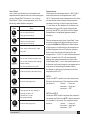
WARNING:
Children should not use PowerPool™ or
hot tubs without adult supervision.
WARNING:
Do not use PowerPool™ or hot tubs unless all
suction guards are installed to prevent body
and hair entrapment.
WARNING:
People using medications and/or having an
adverse medical history should consult a
physician before using a PowerPool™ or hot tub.
WARNING:
People with infectious diseases should not
use a PowerPool™ or hot tub.
WARNING:
To avoid injury exercise care when entering
or exiting the PowerPool™ or hot tub.
WARNING:
Water temperature in excess of 38° C may
be injurious to your health.
WARNING:
Do not use drugs or alcohol before or during
the use of a PowerPool™ or hot tub to avoid
unconsciousness and possible drowning.
WARNING:
Pregnant, or possibly pregnant, women should
consult a physician before using a PowerPool™
or hot tub.
WARNING:
Before entering the PowerPool™ or hot tub
measure the water temperature with an
accurate thermometer.
WARNING:
Do not use a PowerPool™ or hot tub
immediately following strenuous exercise.
WARNING:
Prolonged immersion in a PowerPool™ or
hot tub may be injurious to your health.
WARNING:
Do not permit electric appliances (such as a
light, telephone, radio, or television) within
1.5m of the PowerPool™ or hot tub.
WARNING:
Maintain water chemistry in accordance with
manufacturer’s instruction.
WARNING:
The use of alcohol or drugs can greatly
increase the risk of fatal hyperthermia in hot
tubs and PowerPool™.
IMPORTANT SAFETY WARNINGS

3
3
PowerPool™
GFCI Alert 1
Important Safety Warnings 2
Table of Contents 3
Important Safety Instructions 4
Do’s and Don’ts 5
Hyperthermia 6
PowerPool™ installation 7
Site and Positioning 7
Outdoor Installation 8
Indoor Installation 8
PowerPool™ System Components 9
PowerPool™ Components 10
Jets and Air Controls 11
Jets 11
Cleaning or Replacing Jets 11
Air Controls 12
Electrical Information 13
Important Safety Instructions 13
Installation Options 13
Start Up Procedures 15
Priming Your PowerPool™ 15
Powerpool™ Control System 16
Operating Instructions 16
User’s Pads 17
Temperature Controls 17
Temperature Lock 18
Temperature Unlock 18
Panel Lock 18
Panel Unlock 18
Operating Modes 18
Time and Filtration Cycles 19
Setting the Time 19
Preset Filter Cycles 19
Changing Filter Cycles 19
Clean-Up Cycle 20
Inversion Feature 20
Light 20
Ozone Operation 21
Entertainment System (Optional) 21
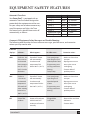
Safety Features 23
Automatic Time Outs 23
Common LCD Equipment Messages 23
Common LCD Messages 24
Maintenance 25
Water Chemistry 25
Sanitizing 25
pH Level 25
Water Maintenance 25
Sanitizing With Ozone 26
Specialty Chemicals 26
Draining Your PowerPool™ 26
Filter Maintenance 27
Winterising 27
PowerPool™ Cabinet Care 28
PowerPool™ Surface Care and Cleaning 28
Underwater LED light cluster 28
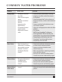
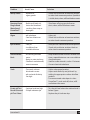
Common Water Problems 29
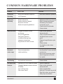
Common Hardware Problems 32
PowerPool™ Soaking Guidelines 34
460 Series System Wiring Diagram 36
TABLE OF CONTENTS

4
4
PowerPool™
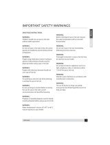
IMPORTANT SAFETY INSTRUCTIONS
1. READ AND FOLLOW ALL
INSTRUCTIONS
2. WARNING - To reduce the risk of injury,
do not permit children to use this prod-
uct unless they are closely supervised at
all times.
3. A wire connector is provided on this unit
to connect a minimum 6 AWG (5.15 mm
2
)
solid copper conductor between this unit
and any metal equipment, metal enclosu-
res of electrical equipment, metal water
pipe, or conduit within 5 feet (1.5m) of
the unit.
4. (For cord-connected/convertible units)
DANGER - Risk of injury.
a. Replace damaged cord immedi-
ately.
b. Do not bury cord.
c. Connect to a grounded, ground-
ing type receptacle only.
5. DANGER - Risk of Accidental Drown-
ing. Extreme caution must be exercised
to prevent unauthorized access by
children. To avoid accidents, ensure that
children cannot use this spa unless they
are supervised at all times.
6. DANGER - Risk of injury. The suction
ttings in this spa are sized to match the
specic water ow created by the pump.
Should the need arise to replace the
suction ttings or the pump, be sure that
the ow rates are compatible.
Never operate spa if the suction ttings
are broken or missing. Never replace a
suction tting with one rated less than
the ow rate marked on the original suc-
tion tting.
7. DANGER - Risk of Electric Shock. Install at
least 5 feet (1.5m) from all metal surfaces.
As an alternative, a spa may be installed
within 5 feet of metal surfaces if each
metal surface is permanently connected
by a minimum 6 AWG (5.15 mm
2
) solid
copper conductor to the wire connector
on the terminal box that is provided for
this purpose.
8. DANGER - Risk of Electric Shock. Do not
permit any electric appliance, such as a
light, telephone, radio, or television,
within 5 feet (1.5m) of a spa.
9. WARNING - To reduce the risk of injury:
a. The water in a spa should never
exceed 40°C (104°F). Water tem-
peratures between 38°C (100°F)
and 104°F (40°C) are considered safe for a
healthy adult. Lower water temperatures
are recommended for young children and
when spa use exceeds 10 minutes.
b. Since excessive water temperatures
have a high potential for causing fetal
damage during the early months of preg-
nancy, pregnant or possibly pregnant
women should limit spa water tempera-
tures to 38°C (100°F).
c. Before entering a spa the user should
measure the water temperature since the
tolerance of water temperature-regulat-
ing devices varies.
d. The use of alcohol, drugs, or medica-

5
5
PowerPool™
tion before or during spa use may lead
to unconsciousness with the possibility of
drowning.
e. Obese persons and persons with a
history of heart disease, low or high
blood pressure, circulatory system prob-
lems, or diabetes should consult a physi-
cian before using a spa.
10. SAVE THESE
INSTRUCTIONS
NOTE: Check with your state/local code
enforcement ocer to determine electrical
code requirements and compliance. Use a
qualied licensed electrician to complete all
spa nal electric connections.
TO AVOID RISK OF ELECTRICAL SHOCK:
1. A green colored terminal or a terminal
marked G, GR, Ground, Grounding, or the
international symbol is located on
the side of the supply terminal box or
compartment. This terminal must be
connected to the grounding means
provided in the electric supply service
panel, using a continuous copper wire
equivalent in size to the circuit conduc-
tors supplying this equipment.
*IEC Publication 417, Symbol 5019.
2. At least two lugs marked “BONDING
LUGS” are provided on the external sur-
face or on the inside of the supply termi-
nal box or compartment. Connect the
local common bonding grid (house-hold
ground) in the area of the hot tub or spa
to these terminals, using an insulated or
bare copper conductor not smaller than
No. 6 AWG.
3. All eld-installed metal components such
as rails, ladders, drains or similar hard
ware located within 5 ft. of the spa or
hot tub shall be bonded to the equip-
ment grounding bus with copper con-
ductors not smaller than No. 6 AWG.
4. Never connect unit to a power supply
with a load controller.
5. Install to provide drainage of compart-
ment for electrical components.
6. The electrical supply for this product
must include a suitably rated switch
or circuit breaker to open all ungrounded
supply conductors. This disconnecting
means must be readily accessible for
operation but installed at least 1.5m
from the spa. All electrical connections
should comply with local regulations.
Do’s and Don’ts
For years of spa enjoyment:
Do:
• Save these instructions!
• Replace the cover immediately after use.
•
Keep the cover locked when spa is not
in use.
• Be aware of the dangers of a wet and
slippery surface. Use caution when
entering and exiting your spa.
• Have a licensed electrician make all nal
electrical connections.
•
Replace worn, frayed or broken electrical cords.
• Keep the water chemistry correctly
balanced. Untreated spa water will cause
Caution: Risk of electrical shock.
Read and follow all instructions.

6
6
PowerPool™
problems with your spa and equipment
as well as being a health risk.
• Clean the spa lter monthly or as needed.
• Position the spa so that all sides remain
accessible for maintenance.
• Use a bathing cap for long hair.
• Refer to information on hyperthermia,
next page.
• Use only authorized spa care products
for the best performance and to keep
the water properly balanced.
Don’t:
• Use the spa at 104°F (40°C) for long
periods of time (more than 30 minutes).
See Hyperthermia, below.
• Use an extension cord to power your spa.
• Allow anyone to stand on the spa cover.
It is not designed to support weight.
• Power the spa unless it is lled with water
to the water level mark on the Weir door.
• Operate the pump on high speed for ex-
tended periods of time with the cover in
place. Extended operation can cause heat
build-up and interfere with spa operation.
Hyperthermia
The causes, symptoms, and eects of
hyperthermia may be described as follows:
Hyperthermia occurs when the internal
temperature of the body reaches a level
several degrees above the normal body
temperature of 98.6°F (37°C). The symptoms
of hyperthermia include an increase in the
internal temperature of the body, dizziness,
lethargy, drowsiness, and fainting. The eects
of hyperthermia include:
a. Failure to perceive heat
b. Failure to recognize the need to exit spa
or hot tub
c. Unawareness of impending hazard
d. Fetal damage in pregnant women
e. Physical inability to exit the spa or hot
tub, and
f. Unconsciousness resulting in the danger
of drowning.
WARNING The use of alcohol, drugs,
or medication can greatly increase the
risk of fatal hyperthermia.

7
7
PowerPool™
POWERPOOL™ INSTALLATION
Danger: Electrical shock risk. Install at
least 1.5m from all metal surfaces.
The electrical supply for this product must
include a suitably rated switch or circuit
breaker to open all ungrounded supply
conductors. The disconnecting means must
be readily accessible but installed at least
1,5 meters from the PowerPool™ water. All
electrical connections should comply with
local regulations.
The appliance should be
supplied through a residual
current device (RCD) with a
rated tripping current not
exceeding 30 mA. Means
for disconnection must
be incorporated in the
xed wiring in accordance
with the wiring rules. Parts containing live
parts, except parts supplied with safety
extra-low voltage not exceeding 12 V, must be
inaccessible to a person in the bath. Earthed
appliances must be permanently connected
to xed wiring.
Site and Positioning
MAAX® Spas recommends that a PowerPool™
be placed in its nal installation site by crane.
In any installation where a crane cannot
be used, you may want to consult with a
professional rigging company.
When utilizing a crane for delivery, be sure
that crane operator understands the weight of
the PowerPool™, the height it must be lifted,
and the distance that the crane boom must
travel. Be sure that the crane operator uses
an 8’ spreader bar and that the straps wrap
all the way around the bottom frame of the
PowerPool™.
Locate the PowerPool™ on a solid, level
foundation keeping in mind the weight of
the lled PowerPool™ (in excess of 24,250lb.
(11,000 kg.) on some models). If you have
any doubts about the load bearing ability
of your chosen site, contact an architect or a
building contractor. The entire perimeter of
the PowerPool™ Frame and bottom must be
evenly supported.
We recommend that you provide a concrete
foundation pad for the PowerPool™. The
foundation pad should be wider and longer
than the PowerPool™ by at least 12 inches
(30 cm) in each direction. Failure to provide a
level surface could structurally damage your
PowerPool™ and void the warranty.
The PowerPool™ must be installed to allow
access for service and maintenance on all
four sides; therefore, if you choose to install
your PowerPool™ below grade level, you will
be required to have a vault or pit constructed
to prevent ground water, rain, snowmelt, or
sources of water from collecting around the
equipment of the PowerPool™. The vault
must have either sucient drainage through a
drain line or through the use of a sump pump.
The vault must have adequate safe access
as to allow for routine maintenance of the
PowerPool™ components.
WARNING: ACCESS TO THE POWERPOOL™
SHOULD BE CONTROLLED IN ACCORDANCE

8
8
PowerPool™
WITH ALL APPLICABLE NATIONAL AND
LOCAL CODES. IN SOME LOCATIONS THIS
MAY INCLUDE AN APPROVED FENCE WITH
SELF-CLOSING, SELF-LOCKING GATE
AND/OR A LOCKABLE SAFETY HARDCOVER
FOR OUTDOOR USE AND A LOCKABLE
DOOR AND/OR SAFETY HARDCOVER FOR
INDOOR USE.
Outdoor Installation
The following considerations apply when
installing your PowerPool™ outdoors:
1. Local codes pertaining to fencing.
2. Local electrical and plumbing codes.
3. View from your house.
4. Wind direction.
5. Exposure to sunlight.
6. Location relationship to trees (twigs,
leaves and shade).
7. Dressing and bathroom location.
8. Storage area for maintenance equipment
and chemicals.
9. Location to facilitate adult supervision.
10. Landscaping and night time lighting.
11. Accessibility to equipment.
12. Location and routing of power supply to
PowerPool™ and foot trac.
Indoor Installation
In addition to the Outdoor installation
consideration, please also understand that the
following considerations apply when installing
your PowerPool™ indoors:
1. Indoor PowerPool™ promote high
humidity. Using either ventilation fans or
commercial grade de-humidiers will help
to reduce the humidity. Consult your
dealer for details.
2. Floor drains must be provided near the
PowerPool™ to drain o water that
may cause falls and /or water damage.
Water will splash out of the PowerPool™
during normal use when swimming and
when exiting the PowerPool™.
3. Surface area of foundation pad and
surrounding area should be at with a
non-skid nish. Carpeting or other
porous materials may retain moisture,
which leads to mold, mildew and odors
and is not recommended.
4. Walls, ceilings, woodwork should be made
of materials capable of withstanding high
humidity.
5. MAAX® Spas only recommends the use of a
concrete foundation pad to support your
PowerPool™. If you intend to install your
PowerPool™ in an area where you cannot
utilize a concrete foundation pad, you
must consult with a structural engineer
to ensure the oor load bearing capacities
are adequate to support the concentrated
PowerPool™ weight, the weight of the
PowerPool™ occupants, and any furniture
or people that will be using the immediate
area of the PowerPool™.
6. During shipment from the factory,
plumbing components may loosen;
therefore it is imperative that the
PowerPool™ is double checked for leaks
before installing to avoid possible water
damage. Your dealer may include this
service in their installation procedures.
7. Indoor sunrooms are capable of
maintaining high ambient temperatures
which may aect the PowerPool™ water
temperature. It is NOT recommended that
you operate your lter cycles for longer
than 4 hours per day under these
conditions.
Danger: Electrical shock risk. Install at least
5 feet (1.5 m) from all metal surfaces.

9
9
PowerPool™
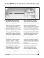
POWERPOOL™ SYSTEM COMPONENTS
A. Filter Skimmer/Weir Door: Removes
oating debris from the water surface,
provides a water return path to equipment,
and houses water lter elements.
PowerPool™ Sport and Pro models utilize
2 Filter Skimmers and the PowerPool™
SuperSport model utilizes 3 Filter Skimmers.
B. Topside Control Panel: Used to control
temperature setting, jet pumps, circulation
system, underwater lights and ambient
eect lighting. PowerPool™ Sport and Pro
models utilize one topside control panel.
The PowerPool™ SuperSport model utilizes
two topside control panels, one for the hot
tub portion and one for the swim area.
C. Air Controls: Increases or decreases air
entering the jets. Close during heating
for maximum eciency. It is recom-
mended that air controls to the MAAX®-
Force swim jets remain closed during
swimming to provide a clearer stream of
water which is free from air bubbles.
D. Equipment Pack Service Panel (no user
serviceable parts): Spa support system
consisting of electronic control pack,
pumps, heater, UV water sanitizer, plasma
UV ozone generator, LED lighting interface
and associated electrical controls (not
shown). The PowerPool™ Sport and
Pro models feature one control pack,
three jet pumps, one UV sanitizer, one
plasma UV ozone generator and one LED
lighting interface. The PowerPool™
SuperSport model features two independent
electronic control packs, four jet pumps,
two UV sanitizers, two plasma UV ozone
generators and two LED lighting interfaces.
E. Drain Access (Adjacent to the equipment
service panel): PowerPool™ drain faucets
are located immediately behind the front
door panel. Remove panel to access.
F. Manufacturer’s Identication Label:
Contains identication information for
warranty service (serial number, model
number, etc.) and electrical information
(ampere rating and ampere requirements).
Located on the lower right side of the front
door panel.
G. Diverter Valve: Used to direct the ow
of water between the massage jets in
the hydrotherapy seats and the swim
jets. By turning the diverter valve
clockwise, the water is directed to the
massage jets in the hydrotherapy seats and
by turning the diverter jet counterclockwise,
the water is directed to the swim jets.

10
10
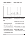
PowerPool™
POWERPOOL™ COMPONENTS
Reference only. Equipment is not always as shown
Note: No consumer serviceable parts. We
recommend that only an authorized service
technician perform PowerPool™ repair or
service.
A. Pumps: Each pump features dual-speed
capacity. Low speed is utilized for ecient
water circulation during ltration and
heating, and for lighter therapy and exercise
programs; high speed is engaged for
maximum action of the jets when deeper
therapy or more rigorous exercise programs
are desired. All pump functions are activated
by topside controls.
B. Electronic Control Pack: All PowerPool™
functions are operated by this control. There
are no user-serviceable components in this
control. Opening this control may subject
you to high voltage and danger of electrical
shock or electrocution.
Warning and Installation Label: Contains
important safety information, hazard
warnings and installation instructions.
C. Slice Valve: Used to shut o water ow
from the PowerPool™ vessel to pumps
and electronic control pack while servicing.
Quantity will vary depending on model.
All valves should be open during normal
operations.
D. Electrical Connections: Contains outlets for
electrical plug connections. Connections are
made during manufacture of the pool.
E. Heater Assembly: Thermostatically
controlled and equipped with an overheat
safety shut-o.

11
11
PowerPool™
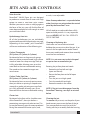
JETS AND AIR CONTROLS
Swim Area Jets
PowerPool™ MAAX®-Force jets are designed
to produce a smooth ow of water with high
output to create a consistent swim stream.
Whether you want to swim or walk/jog against
the force of the jets, you will nd the ow of
water deep enough and swift enough to meet
your individual needs.
Hydrotherapy Area Jets
All of the hydrotherapy jets are individually
engineered to provide a unique hydro-massage.
Depending on the model, your PowerPool™
will have a combination of the following jets:
Cyclone Therapeutic
(XL Cyclone, LS Cyclone, & Cyclone):
Positioned to focus on large muscle groups,
these jets deliver a concentrated, high volume
stream of water for a deep massage. Each jet
is fully adjustable, allowing users to set the
water ow to the most comfortable setting.
The nozzle can be rotated to target sore
muscle areas.
Cyclone Turbo Swirl Jets
(XL Cyclone, LS Cyclone, & Cyclone):
Positioned to focus on muscle tension zones,
these jets deliver a spinning V-shaped water
stream for a gentle, pulsating massage. Each
jet is fully adjustable, allowing users to set
the water ow to the most comfortable setting.
Cluster Jets:
Positioned in the foot well or shoulder areas
of the PowerPool™, these jets deliver a
penetrating massage to dissolve tension. This
jet may be the entry point for ozone produced
during the automatic ltration cycles, and,
as such, is not adjustable.
Note: Ozone production is suspended when
other functions are activated on the control
panel by the PowerPool™ user.
All full sized jets are adjustable from a fully
open to closed position. It is very important
that you NEVER SHUT ALL FULL SIZED JETS
OFF AT ONE TIME!
Cleaning or Replacing Jets
Hard water can cause calcium/mineral
buildup that can restrict or bind the jets. A jet
consists of a face plate and a nozzle. Rotate
these parts weekly and remove/clean monthly
to ensure free movement.
NOTE: It is not necessary to drain the pool
or spa to clean or remove the jets.
Rotating the jet face plate and nozzle
• Rotate the jet face left and right
(open and closed).
• Return the face plate to the full open
position.
• Turn the jets on to high speed.
• Twist the nozzle left and right.
• Rotate the nozzle in the socket.
NOTE: If the jet insert disengages from the
PowerPool™ housing, see steps to reinstall
below.
Cleaning the jets
To remove the jet insert, use the palm of your
hand to exert pressure on the face of the jet.
Turn counterclockwise until the jet ‘clicks’.
Gently pull the jet assembly from the housing.

12
12
PowerPool™
To clean the jet insert and housing, use a
pressurized hose and spray the inside of
the jet. Soak the jet in a diluted PowerPool™
cleaning solution, rinse. Wipe the inside of the
housing to remove any debris.
To reinstall the jet, line up the tab on the
backside of the barrel with the groove in the
body. Use the palm of your hand to gently tab
the jet until it snaps into position.
Air Controls
The intensity of the jet action can be
controlled by altering the amount of air
injected with water through the jets. Your
PowerPool™ has 2 to 4 air controls located
on the lip of the PowerPool™. Each control
activates air to specic jets in the PowerPool™
allowing you to create various combinations
and levels of jet action to suit individual
preferences. Turn the control counter-
clockwise to turn the air o and clockwise to
turn air on.
NOTE: Air controls should be closed
during heating cycles for maximum
energy eciency.

13
13
PowerPool™
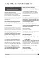
ELECTRICAL INFORMATION
Important Safety Instructions
All electrical connections to this spa package
MUST be accomplished by a qualied
licensed electrician in accordance with the
National Electrical Code (NEC) and with state/
local electrical codes in eect at the time
of installation.
NOTE: Prior to performing any service to
the spa equipment, turn OFF all primary
electrical power at the main circuit breaker
or disconnect panel.
To make spa electrical connections, remove
the exterior equipment access panel, locate
the electrical control box, remove the control
box cover and follow the wiring diagram on
the inside of the control box cover.
Connections should be made using copper
conductors only. Connecting wires, circuit
breakers, or fuses must all be sized to accom-
modate the Total Ampere load as specied
on the equipment label.
This equipment is designed to operate on
60Hz alternating current only, at 240 volts.
NOTE: All unions must be hand-tight and
all slice valves must be locked in the OPEN
position before lling or relling spa!
A clip is provided to help keep the slice
valve open. Run spa and check for union
leaks before reinstalling front panel.
Ground-Fault Circuit Interrupter
A qualied licensed electrician shall connect
the spa to a circuit protected by a GFCI. This
is a requirement by the National Electric
Code, article 680-42, and is also in compli-
ance with Underwriter’s Laboratories, Inc.
Installation Options
While knockouts are provided in the cabinet
base to bring the conduit to the equipment
compartment, a hole may need to be drilled
in the pedestal or base if an alternate electri-
cal service entrance is desired.
Refer to the manufactures’s nameplate
located on the kick plate to determine your
spa’s ampere requirements.
240 Volt Installation
Permanently Connected:
The Super Sport spa side must be connected
to a 240 volt electric service.
Electrical Requirements:
240 volt, 60 Hz, single phase, 40 amp., •
4-wire service (line 1, line 2, neutral,
and ground or,
*30 Amp Option
Note: The heater can be activated only with
the pump on low speed. Only the spa light
can be operating at the same time without
disabling the heater. See your authorized
MAAX Spas dealer to select this option.
240 Volt Installation
Permanently Connected:
The Sport, Pro and Super Sport swim side
must be connected to a 240 volt electric
service.
Caution: Risk of electrical shock.
Read and follow all instructions.

14
14
PowerPool™
Electrical Requirements:
240 volt, 60 Hz, single phase, 50 or •
60 amp., 4-wire service (line 1, line 2,
neutral, and ground or,
*40 Amp Option
Note: The heater can be activated only with
the pump on low speed. Only the spa light
can be operating at the same time without
disabling the heater. See your authorized
MAAX Spas dealer to select this option.
Spas installed for 240 volt, 60 Hz, single
phase operation require a 4-wire, 50 or 60
amp 240 volt sub-feed in non-metallic pipe
to the spa equipment compartment (line 1,
line 2, neutral and ground). A green colored
terminal (or wire connector marked “G”,
or “GR”, or “Grounding”) is provided in the
control box. To reduce the risk of electrical
shock, connect this terminal or connector
to the grounding terminal of your electrical
service or supply panel with a continuous
green insulated copper wire equivalent to
the circuit conductor supplying this equip-
ment, but no smaller than No. 12 AWG. A
second pressure wire connector is provided
on the surface of the control box for bond-
ing to local ground points. To reduce the
risk of electrical shock. this connector should
be bonded with a No. 6 AWG copper wire to
any metal ladders, water pipes, or any metal
within 5 feet of the spa.
Note: Copper wire is strongly recommend-
ed for all electrical connections.

15
15
PowerPool™
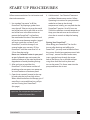
START UP PROCEDURES
Follow recommendations for site location and
electrical connection.
1. Use standard “tap water” to ll the
PowerPool™ by draping a garden hose
over the wall. Take care to wrap the metal
end of the hose with a soft cloth or set the
end of the hose in the lter canister to
protect the PowerPool™ surface from
the metal end of the hose. The metal end
of your hose can become rough or jagged
and may scratch the surface of your
PowerPool™, and this damage is not
covered under your warranty. Fill the
PowerPool™ until the water level is 2 to
2,5 cm from the top lip.
Never use “softened” water in your pool
or spa. Softened water can impact the
chemical balance of the water and lead to
degradation of metal plumbing ttings.
2. After you have assured that the
PowerPool™ is full of water and that all
plumbing valves are open, turn power on
at circuit breaker or disconnect panel.
3. Open the air controls, located on the top
lip, and cycle the jets from high to low.
Water should come from the therapy jets. If
water ow is not established, turn o jets
and see Priming Your PowerPool™
(this page).
4. Add chemicals. See Chemical Treatment
and Water Maintenance section. Follow
Operating Instructions for your particular
model to set heat to the desired
temperature. Initially, you may nd that the
PowerPool™ requires 18 to 24 hours on
230 Volt installations to reach temperature.
Keep your thermal cover on the unit and
close the air controls to help the heating
process.
Priming Your PowerPool™
When lling your PowerPool™ for the rst
time or, after draining and relling the
PowerPool™, you may need to bleed air from
the system. Should you experience an air-lock
on Pump 1, remove the lter basket cover,
insert a garden hose through the center
hole of the lter as far as possible without
using force. Hold the hose in place and
turn on the water. This forces water into the
pump and forces the air out.
Important: Do not operate the PowerPool™
without full water ow.

16
16
PowerPool™
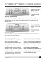
POWERPOOL™ SERIES CONTROL SYSTEM
The 460 Control System oers you the
ultimate in PowerPool™ control. The backlit,
Liquid Crystal Display (LCD) displays
current water temperature, set point water
temperature, time, and operating mode
settings. Each feature of the system is actuated
through a control panel touch pad. Touch
the appropriate pad to activate the desired
function. At start up, when power is supplied
to the PowerPool™, the controls will operate
properly and safely under the factory settings.
The PowerPool™ will be in Standard Mode,
a temperature setting of 100°F (38°C), and
a ltration cycle duration of 2 hours. To fully
utilize the unique capabilities of the control
system, it is important to know how to set the
temperature, operate the pumps, operate the
light, adjust the mode setting, and change the
ltration cycles.
NOTE: In event of a power outage or
failure, the Control System should retain all
settings, except time of day. If settings are
lost, re-program per the instructions in this
manual and contact your dealer.
PowerPool™ swim zone control
All PowerPool™ models utilize the topside control panel shown above. This control panel
operates all functions of the PowerPool™ for the Sport model and the Pro model. This control
operates only the swim zone section of the SuperSport model. This control supports the
following features:
PowerPool™ spa control
• 3 Dual-speed Jet Pumps
• Underwater LED lighting
• Ambient Interior LED
Mood Lighting
• Temperature Setting
• Customized Filtration
Settings
This control operates only the spa zone section of the PowerPool™ SuperSport model. This
control supports the following features:
• 1 Dual-speed Jet Pump
• Underwater LED lighting
• Ambient Interior Mood
Lighting
• Temperature Setting
• Customized Filtration
Settings
Page is loading ...
Page is loading ...
Page is loading ...
Page is loading ...
Page is loading ...
Page is loading ...
Page is loading ...
Page is loading ...
Page is loading ...
Page is loading ...
Page is loading ...
Page is loading ...
Page is loading ...
Page is loading ...
Page is loading ...
Page is loading ...
Page is loading ...
Page is loading ...
Page is loading ...
Page is loading ...
-
 1
1
-
 2
2
-
 3
3
-
 4
4
-
 5
5
-
 6
6
-
 7
7
-
 8
8
-
 9
9
-
 10
10
-
 11
11
-
 12
12
-
 13
13
-
 14
14
-
 15
15
-
 16
16
-
 17
17
-
 18
18
-
 19
19
-
 20
20
-
 21
21
-
 22
22
-
 23
23
-
 24
24
-
 25
25
-
 26
26
-
 27
27
-
 28
28
-
 29
29
-
 30
30
-
 31
31
-
 32
32
-
 33
33
-
 34
34
-
 35
35
-
 36
36
-
 37
37
-
 38
38
-
 39
39
-
 40
40


MAAX Spas Powerpool Owner's manual
- Type
- Owner's manual
- This manual is also suitable for
Ask a question and I''ll find the answer in the document
Finding information in a document is now easier with AI
Related papers

Other documents
-
 QCA Spas MODEL 14 BD Dimensions Guide
-
QCA Spas Model 10 SM Dimensions Guide
-
 Home and Garden Spas LPIXP34 User manual
-
 Cal Spas Portable Spas Owner's manual
-
 DM Industries LD-15 Series User manual
-
 QCA Spas MODEL 1 BD Dimensions Guide
-
 DM Industries ECO spas Deluxe U-130 User manual
-
Lifesmart Playa User manual
-
 Vita Spa Intrigue User manual
-
 PDC spas SYNERGY Series FX15 Owner's manual


