12
pulsar 3
dash indicate, it is generally disabled in the setup window; final discharge voltage Vd (2,80V);
From top right – information window: TC current temperature; supply voltage Vs: (48,4V); amount of consumed
energy Cs: (0Ah); last process information – 2 LiPo cells; charged by 0,063Ah
All process settings are conducted in a very similar way. First, choose the appropriate memory window that is to
be programmed (from M 1 to M 20). Secondly, enter the program window by holding the dial, where the “Mode &
Accu” option is selected. Here the battery type and then Disch. (discharge).
The process parameters can be changed if necessary. Through holding the dial we enter the program window
where we chose the “Parameters” option, which enables us to set all the parameters important for the process for
a particular battery type.
And so:
-exit- – return to memory window.
Ib:x,xx (only for LiXX) – setting the max. balancing current: Ib: 0,00 – no balancing (the voltage of singular
cells will be displayed in the balancer windows); Ib: 0,25 – balancing with a max. current of 0,25A/cell, (for
small capacity packages of 500mAh); Ib: 0,50 – balancing with a current of 0,50A/cell (for packages of 500-
3000mAh); Ib: 1,00 – balancing with a current of 1A/cell (use with all LiFe cells as well as other LiXX cells up
to 2000mAh). While discharging, the balancer has the same voltage limits as when charging.
Auto – when his parameter is enabled, the current will be reduced after reaching the final discharge voltage
by 1/5 of the currently set current. The process will be stopped when the reduced current reaches the value
lower than 1/10 of the set current or then 100mA (the lowest possible current). Example: the discharge
current is 15A. After reaching the current’s final discharge voltage by 1/5 it will give us 12A. After another
current reduction by 1/5 it will be 8A, 6,4A …1,5A. When the “Auto” parameter is disabled, the discharge will
be stopped immediately when the final discharge voltage will be reached (without the current reduction –
which is 15A in the example given).
Revers – a return of energy to the supplying battery (car battery) helps reaching a higher discharge power.
When setup (as the “higher power”) blocks this function, but it will be enabled the memory window a dash
will be displayed before the “Revers” sign (-Revers). When this function will be enabled in the setup, the
dash will disappear from all memory Windows, in which Revers is present, and the function will be enabled
(the dash will be replaced by a „√“). To easily recognize if the energy return is in progress during the
process, a discharge animation will be displayed three times faster than during discharge without the energy
return. There will also be an “R” letter underneath the animation, and if that “R” is displayed alternately with
“V” (Volt) – the current reduction Has occurred after exceeding the supply batteries’ voltage (Vrev – setup).
WARNING: enabling the energy return when the charger is supplied by an AC adapter may lead to damage
to the adapter!
Vd – final discharge voltage settings. If the set value is other than the recommended settings, an
exclamation mark will be displayed (! Vd). For cell types: LiPo 2,80-3,60 V/cell; LiHV 2,8-3,60 V/cell; Li-Ion
2,50-3,30 V/cell; LiFe 2,30-3,10 V/cell NiZn 1,00-1,40 V/cell; NiMH 0,80-1,10V/cell; NiCd 0,60-0,95V/cell;
Pb 1,60-1,90V/ell. We advise using standard settings.
Setting discharge current
After a press of the dial the required current can be set In the memory window, and after confirming (press of the
dial) the limiters’ value. The current’s value can be between 0,1A to 0,25A set in the following intervals: 0,1A
intervals up to 10,0A, 0,5A above 10A. The limiter’s capacity is set from “-,-Ah” (the capacity is not controlled) to
200Ah. Setting the limiter with LiXX batteries is crucial only in a particular case.
After all settings meet our requirements we can plug in the battery packages to the charger. Before beginning the
process it is necessary to check if the number of cells in the package matches that indicated by the charger. After
adjusting the number of cells, if necessary, we can start the process by pressing the Rotary knob.
Warning: all packages with a balancing connection must always be plugged in the following order – first the
balancer, then the charging cable. Thanks to this the charger will always recognize the right amount of cells in the
package! It is important to check if the number of cells in the package has been properly recognized before
starting the process. After adjusting the number of cells, if necessary, we can start the process by pressing the
Rotary knob.
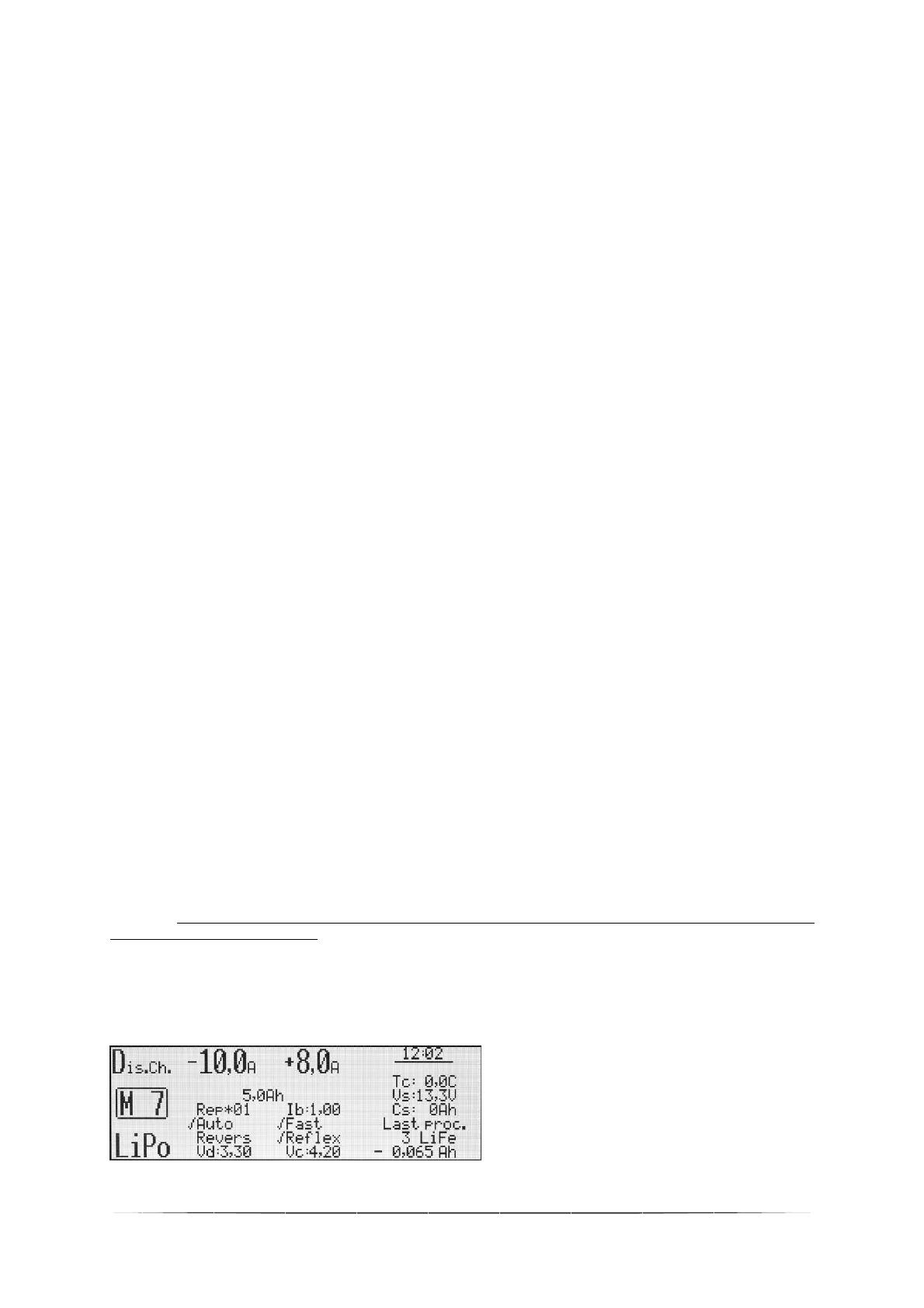
Double processes set-up e.g. charging/discharging
Window description. Charging/discharging is set;
in memory window M 7; LiPo battery type;
discharge current 10A; charge current 8A; 5Ah
limiter.
In the column under the discharged current –
discharge parameters (REP*01 – one cycle); under
the charge current – charge parameters


