Page is loading ...

ADCP-61-825
Issue 2
December 2004
1306704 Rev A
RF Worx
®
SignalOn
™
Series
Forward Path Amplifier Products
User Manual

ADCP-61-825 • Issue 2 • December 2004 • Preface
Page ii
COPYRIGHT
© 2004, ADC Telecommunications, Inc.
All Rights Reserved
Printed in the U.S.A.
REVISION HISTORY
LIST OF CHANGES
The technical changes incorporated into this issue are listed below.
TRADEMARK INFORMATION
ADC and
RF Worx
are registered trademarks of ADC Telecommunications, Inc., SignalOn is a trademark of ADC
Telecommunications, Inc.
DISCLAIMER OF LIABILITY
Contents herein are current as of the date of publication. ADC reserves the right to change the contents without prior notice. In no
event shall ADC be liable for any damages resulting from loss of data, loss of use, or loss of profits and ADC further
disclaims any and all liability for indirect, incidental, special, consequential or other similar damages. This disclaimer of
liability applies to all products, publications and services during and after the warranty period.
This publication may be verified at any time by contacting ADC’s Technical Assistance Center at 1-800-366-3891, extension 73475
(in U.S.A. or Canada) or 952-917-3475 (outside U.S.A. and Canada), or by e-mail to bcg_tac@adc.com.
ISSUE DATE REASON FOR CHANGE
1 05/2004 Original publication
2 12/2004 Add 2RU power option and 20dB amplifier
PAGE IDENTIFIER DESCRIPTION OF CHANGE
All – Add specifications, figures, and text for powered 2RU 8-position chassis and 20dB amplifier.
ADC Telecommunications, Inc.
P.O. Box 1101, Minneapolis, Minnesota 55440-1101
In U.S.A. and Canada: 1-800-366-3891
Outside U.S.A. and Canada: (952) 917-3475
Fax: (952) 917-1717

ADCP-61-825 • Issue 2 • December 2004 • Preface
Page iii
© 2004, ADC Telecommunications, Inc.
TABLE OF CONTENTS
Content Page
ABOUT THIS MANUAL . . . . . . . . . . . . . . . . . . . . . . . . . . . . . . . . . . . . . . . . . . . . . . . . . . . . . . . . . . . . . . . . . . . . . . . . . v
ADMONISHMENTS . . . . . . . . . . . . . . . . . . . . . . . . . . . . . . . . . . . . . . . . . . . . . . . . . . . . . . . . . . . . . . . . . . . . . . . . . . . v
GENERAL SAFETY PRECAUTIONS . . . . . . . . . . . . . . . . . . . . . . . . . . . . . . . . . . . . . . . . . . . . . . . . . . . . . . . . . . . . . . . . . v
CERTIFICATION . . . . . . . . . . . . . . . . . . . . . . . . . . . . . . . . . . . . . . . . . . . . . . . . . . . . . . . . . . . . . . . . . . . . . . . . . . . . . v
FCC COMPLIANCE STATEMENT . . . . . . . . . . . . . . . . . . . . . . . . . . . . . . . . . . . . . . . . . . . . . . . . . . . . . . . . . . . . . . . . . . . v
STANDARDS . . . . . . . . . . . . . . . . . . . . . . . . . . . . . . . . . . . . . . . . . . . . . . . . . . . . . . . . . . . . . . . . . . . . . . . . . . . . . . .vi
LIST OF ACRONYMS AND ABBREVIATIONS . . . . . . . . . . . . . . . . . . . . . . . . . . . . . . . . . . . . . . . . . . . . . . . . . . . . . . . . . . .vi
1 GENERAL . . . . . . . . . . . . . . . . . . . . . . . . . . . . . . . . . . . . . . . . . . . . . . . . . . . . . . . . . . . . . . . . . . . . . . . . . . . . . 1
1.1 Compatibility with RF Worx Product Line . . . . . . . . . . . . . . . . . . . . . . . . . . . . . . . . . . . . . . . . . . . . . . . . . 1
2 PRODUCT DESCRIPTION . . . . . . . . . . . . . . . . . . . . . . . . . . . . . . . . . . . . . . . . . . . . . . . . . . . . . . . . . . . . . . . . . . 1
2.1 Physical Description . . . . . . . . . . . . . . . . . . . . . . . . . . . . . . . . . . . . . . . . . . . . . . . . . . . . . . . . . . . . . . . 1
2.1.1 Forward Path Amplifier . . . . . . . . . . . . . . . . . . . . . . . . . . . . . . . . . . . . . . . . . . . . . . . . . . . . . . 1
2.1.2 Chassis . . . . . . . . . . . . . . . . . . . . . . . . . . . . . . . . . . . . . . . . . . . . . . . . . . . . . . . . . . . . . . . . . 2
2.1.3 Power Supply . . . . . . . . . . . . . . . . . . . . . . . . . . . . . . . . . . . . . . . . . . . . . . . . . . . . . . . . . . . . . 4
2.2 Functional Description . . . . . . . . . . . . . . . . . . . . . . . . . . . . . . . . . . . . . . . . . . . . . . . . . . . . . . . . . . . . . . 5
2.2.1 Forward Path Amplifier . . . . . . . . . . . . . . . . . . . . . . . . . . . . . . . . . . . . . . . . . . . . . . . . . . . . . . 5
2.2.2 Power Supplies. . . . . . . . . . . . . . . . . . . . . . . . . . . . . . . . . . . . . . . . . . . . . . . . . . . . . . . . . . . . 6
2.2.3 A/B Redundancy . . . . . . . . . . . . . . . . . . . . . . . . . . . . . . . . . . . . . . . . . . . . . . . . . . . . . . . . . . . 6
3 PLANNING . . . . . . . . . . . . . . . . . . . . . . . . . . . . . . . . . . . . . . . . . . . . . . . . . . . . . . . . . . . . . . . . . . . . . . . . . . . . 6
3.1 Cooling Considerations . . . . . . . . . . . . . . . . . . . . . . . . . . . . . . . . . . . . . . . . . . . . . . . . . . . . . . . . . . . . . 7
4 INSTALLATION . . . . . . . . . . . . . . . . . . . . . . . . . . . . . . . . . . . . . . . . . . . . . . . . . . . . . . . . . . . . . . . . . . . . . . . . . 9
4.1 Chassis Installation . . . . . . . . . . . . . . . . . . . . . . . . . . . . . . . . . . . . . . . . . . . . . . . . . . . . . . . . . . . . . . . . 9
4.2 Connect Chassis Ground . . . . . . . . . . . . . . . . . . . . . . . . . . . . . . . . . . . . . . . . . . . . . . . . . . . . . . . . . . . . 10
4.3 Installing Forward Path Amplifier . . . . . . . . . . . . . . . . . . . . . . . . . . . . . . . . . . . . . . . . . . . . . . . . . . . . . 12
4.4 Installing Power Supply Modules in 5RU Chassis. . . . . . . . . . . . . . . . . . . . . . . . . . . . . . . . . . . . . . . . . . . 13
4.5 Installing Power Supply Modules in 2RU Chassis. . . . . . . . . . . . . . . . . . . . . . . . . . . . . . . . . . . . . . . . . . . 15
4.6 Install 5RU Chassis Door . . . . . . . . . . . . . . . . . . . . . . . . . . . . . . . . . . . . . . . . . . . . . . . . . . . . . . . . . . . 16
4.7 Install Designation Card (5RU Chassis) . . . . . . . . . . . . . . . . . . . . . . . . . . . . . . . . . . . . . . . . . . . . . . . . . 16
4.8 Alarm Connections . . . . . . . . . . . . . . . . . . . . . . . . . . . . . . . . . . . . . . . . . . . . . . . . . . . . . . . . . . . . . . . 17
4.9 Power Connections . . . . . . . . . . . . . . . . . . . . . . . . . . . . . . . . . . . . . . . . . . . . . . . . . . . . . . . . . . . . . . . 18
4.9.1 AC Power Connections . . . . . . . . . . . . . . . . . . . . . . . . . . . . . . . . . . . . . . . . . . . . . . . . . . . . . . 18
4.9.2 DC Power Connections . . . . . . . . . . . . . . . . . . . . . . . . . . . . . . . . . . . . . . . . . . . . . . . . . . . . . . 18
5 CABLE MANAGEMENT . . . . . . . . . . . . . . . . . . . . . . . . . . . . . . . . . . . . . . . . . . . . . . . . . . . . . . . . . . . . . . . . . . . 21
5.1 5RU 20-Position Chassis Cabling. . . . . . . . . . . . . . . . . . . . . . . . . . . . . . . . . . . . . . . . . . . . . . . . . . . . . . 22
5.1.1 Cabinet Considerations . . . . . . . . . . . . . . . . . . . . . . . . . . . . . . . . . . . . . . . . . . . . . . . . . . . . . 22
5.1.2 Module Cabling Considerations. . . . . . . . . . . . . . . . . . . . . . . . . . . . . . . . . . . . . . . . . . . . . . . . 22
5.1.3 General Considerations . . . . . . . . . . . . . . . . . . . . . . . . . . . . . . . . . . . . . . . . . . . . . . . . . . . . . 23
5.2 2RU 8-Position Chassis Cabling. . . . . . . . . . . . . . . . . . . . . . . . . . . . . . . . . . . . . . . . . . . . . . . . . . . . . . . 23
6 OPERATING INSTRUCTIONS. . . . . . . . . . . . . . . . . . . . . . . . . . . . . . . . . . . . . . . . . . . . . . . . . . . . . . . . . . . . . . . 24
6.1 Forward Path Amplifier . . . . . . . . . . . . . . . . . . . . . . . . . . . . . . . . . . . . . . . . . . . . . . . . . . . . . . . . . . . . 24
6.1.1 Gain Adjustment . . . . . . . . . . . . . . . . . . . . . . . . . . . . . . . . . . . . . . . . . . . . . . . . . . . . . . . . . . 24

ADCP-61-825 • Issue 2 • December 2004 • Preface
Page iv
© 2004, ADC Telecommunications, Inc.
TABLE OF CONTENTS
Content Page
6.1.2 Tilt Adjustment. . . . . . . . . . . . . . . . . . . . . . . . . . . . . . . . . . . . . . . . . . . . . . . . . . . . . . . . . . . 25
6.1.3 Monitor Test Ports . . . . . . . . . . . . . . . . . . . . . . . . . . . . . . . . . . . . . . . . . . . . . . . . . . . . . . . . 25
6.2 Power Supply . . . . . . . . . . . . . . . . . . . . . . . . . . . . . . . . . . . . . . . . . . . . . . . . . . . . . . . . . . . . . . . . . . . 25
7 MAINTENANCE . . . . . . . . . . . . . . . . . . . . . . . . . . . . . . . . . . . . . . . . . . . . . . . . . . . . . . . . . . . . . . . . . . . . . . . . 26
7.1 Power Supply Fan Replacement Procedure. . . . . . . . . . . . . . . . . . . . . . . . . . . . . . . . . . . . . . . . . . . . . . . 26
8 SPECIFICATIONS . . . . . . . . . . . . . . . . . . . . . . . . . . . . . . . . . . . . . . . . . . . . . . . . . . . . . . . . . . . . . . . . . . . . . . 28
9 CUSTOMER INFORMATION AND ASSISTANCE. . . . . . . . . . . . . . . . . . . . . . . . . . . . . . . . . . . . . . . . . . . . . . . . . . . 30

ADCP-61-825 • Issue 2 • December 2004 • Preface
Page v
© 2004, ADC Telecommunications, Inc.
ABOUT THIS MANUAL
The RF Worx SignalOn Forward Path Amplifier product line includes gain amplifiers, power
supplies, and power kits. The mechanical dimensions, cable management, and aesthetics of the
amplifier and power supplies are compatible with the RF Worx SignalOn product line. The
system is designed to accommodate superior cable management and ease of use. Amplifier and
power supplies are designed to be installed in the 8- or 20-position SignalOn Series chassis.
Each amplifier or power supply occupies two positions in the chassis.
ADMONISHMENTS
Important safety admonishments are used throughout this manual to warn of possible hazards to
persons or equipment. An admonishment identifies a possible hazard and then explains what
may happen if the hazard is not avoided. The admonishments — in the form of Dangers,
Warnings, and Cautions — must be followed at all times. These warnings are flagged by use of
the triangular alert icon (seen below), and are listed in descending order of severity of injury or
damage and likelihood of occurrence.
GENERAL SAFETY PRECAUTIONS
CERTIFICATION
The RF Worx SignalOn Forward Path products have been tested and found to comply with the
requirements of UL 60950, EN 1950, and CSA 22.2 No. 0.7.
FCC COMPLIANCE STATEMENT
The RF Worx SignalOn Forward Path Amplifier product line has been certified to comply with
the requirements for class A computing devices per part 15 of the FCC regulations.
Danger: Danger is used to indicate the presence of a hazard that will cause severe personal
injury, death, or substantial property damage if the hazard is not avoided.
Warning: Warning is used to indicate the presence of a hazard that can cause severe personal
injury, death, or substantial property damage if the hazard is not avoided.
Caution: Caution is used to indicate the presence of a hazard that will or can cause minor
personal injury or property damage if the hazard is not avoided.
Warning: Never install equipment in a wet location or during a lightning storm.
Warning: Before making any connections to the chassis, verify that the power is off (fuse
removed at the fuse and alarm panel) and that the plug-in module is removed from the chassis.
Do not install plug-in module until after the chassis wiring is completed.

ADCP-61-825 • Issue 2 • December 2004 • Preface
Page vi
© 2004, ADC Telecommunications, Inc.
STANDARDS
LIST OF ACRONYMS AND ABBREVIATIONS
The acronyms and abbreviations used in this manual are detailed in the following list:
AW G American Wire Gauge
ANSI American National Standards Institute
CATV Cable TV
CPE Customer Premise Equipment
CI Customer Interface
FCC Federal Communications Commission
GND Ground
MBB Make-Before-Break
MON Monitor
NID Network Interface Device
RCV Receive
TTL Transistor-Transistor Logic
XMT Transmit
Warning: This equipment generates, uses, and can radiate radio frequency energy and if not
installed and used in accordance with the instruction manual, may cause interference to radio
communications. It has been tested and found to comply with limits for a Class A digital device
pursuant to Subpart B of Part 15 of FCC Rules, which are designed to provide reasonable
protection against such interference when operated in a commercial environment. Operation of
this equipment in a residential area is likely to cause interference to TV and radio reception in
which case the user, at their own expense, will be required to take whatever measures may be
required to correct the interference.
This equipment does not exceed Class A limits for radio emission for digital apparatus, set out
in the radio interference regulation of the authorization methods of Industry Canada. Operation
in a residential area may cause unacceptable interference to TV and radio reception requiring
the owner or operator to take whatever steps are necessary to correct the interference.
EN55022 Limits and Methods of Measurement of Radio Interference Charac-
teristics of Information Technology Equipment
ISTA+7 International Safe Transit Authority
ANSI/SCTE 06 1999 Composite Distortion Measurements
ANSI/SCTE 01 1996 “F” Port (Female Outdoor) Physical Dimensions
NCTA Part 4 NTC REPORT No.7 Video Facility Testing
TR-TSY-000332 Reliability Prediction Procedure for Electronic Equipment

ADCP-61-825 • Issue 2 • December 2004
Page 1
© 2004, ADC Telecommunications, Inc.
1 GENERAL
The RF Worx SignalOn system is a modular system that permits high isolation combining,
splitting, and amplification of headend signals in a CATV system. The system is designed to
accommodate strong cable management, EMI shielding, and ease of use. This facilitates easy
reconfiguration and high performance within a dynamic headend environment.
Each amplifier or power supply occupies two positions in a chassis. Up to nine amplifiers and one
power supply, or eight amplifiers and two load-sharing, redundant power supplies can be installed
in a vertical 20-position RF Worx SignalOn chassis. Ten amplifiers may be installed in the vertical
20-position RF Worx SignalOn chassis if an external +24VDC power source is used.
Each amplifier or power supply occupies two positions in a chassis. Up to three amplifiers and
one power supply, or two amplifiers and two load-sharing, redundant power supplies can be
installed in a horizontal 8-position RF Worx SignalOn chassis. Four amplifiers may be installed in
the horizontal 8-position RF Worx SignalOn chassis if an external +24VDC power source is used.
1.1 Compatibility with RF Worx Product Line
The SignalOn amplifiers and power supplies may be installed in the same chassis as the SignalOn
Passive modules. They are not physically compatible with the existing RF Worx chassis.
2 PRODUCT DESCRIPTION
This section provides physical, functional, and technical descriptions of the RF Worx SignalOn
Forward Path Amplifier, chassis, 100/120/240VAC power supply, and –48VDC power supply.
2.1 Physical Description
2.1.1 Forward Path Amplifier
Each Forward Path Amplifier provides adjustable amplification with low distortion and low
noise for the forward path (50 MHz to 1000 MHz).
The RF Worx Forward Path Amplifier is available in the following variations:
• 20 or 30 dB adjustable gain (F Connectors)
• 20 or 30 dB adjustable gain (BNC Connectors)
Each RF Worx SignalOn Forward Path Adjustable Gain Amplifier has two connectors for
monitor ports on the front panel. Recessed push buttons for gain and tilt control are also located
on the front panel. Two RF connectors are located on the rear panel (RF IN and RF OUT). All
coax connectors are either F or BNC type (depending on model ordered). Each amplifier
acquires its main and redundant +24VDC power from the integral power connector located at
the top-rear of the amplifier module. A front and rear view of the Forward Path Amplifier is
shown in Figure 1.

ADCP-61-825 • Issue 2 • December 2004
Page 2
© 2004, ADC Telecommunications, Inc.
Figure 1. 30 dB Forward Path Amplifier
2.1.2 Chassis
The RF Worx SignalOn chassis provides configuration and connection flexibility in a CATV
broadband service system. Chassis is designed to accommodate RF Worx SignalOn passive
modules, Forward Path Amplifiers, and power supplies in various configurations. There are two
RF Worx SignalOn powered chassis available.
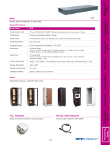
The RF Worx SignalOn 8-position horizontal mount chassis that is 3.49 inches (8.86 cm) or 2 Rack
Units (RU) high, designed for use in 19-inch EIA racks. The
RF Worx
SignalOn 2RU chassis is
shown in
Figure 2
. Optional extender brackets are available for 23-inch rack installation.
The RF Worx SignalOn 20-position vertical mount chassis is 8.75 inches (22.23 cm) or 5 Rack
Units (RU) high, designed for use in 19-inch EIA racks. The RF Worx SignalOn 5RU chassis is
shown in Figure 3. Optional extender brackets are available for 23-inch rack installation.
When the power option is installed the chassis may be connected directly to +24VDC office
power. If AC or –48VDC is required, optional power supply modules may be installed in the
Note: RF Worx
SignalOn Forward Path Amplifiers/Power Supplies require that an optional
power strip/kit be installed in the chassis.
19236-A
FRONT
VIEW
REAR
VIEW
30 dB AMP
50-1000 MHz
POWER
CONNECTOR
MON IN
-20 dB
MON OUT
-20 dB
POWER
+
GAIN
_
+
TILT
_
RF OUT
RF IN

ADCP-61-825 • Issue 2 • December 2004
Page 3
© 2004, ADC Telecommunications, Inc.
chassis. See Section 4.9, Power Connections for details on cabling procedures for the power
supplies. Frame ground screw terminals are located on the rear of the chassis.
Figure 2. 2RU 8-Position Chassis
Figure 3. 5RU 20-Position Chassis with Door Installed
Note:
When installing chassis with amplifiers and power supplies, provisions must be made
allowing for sufficient airflow. See
Section 3.1, Cooling Considerations
for installation
recommendations.
19861-A
19701-A

ADCP-61-825 • Issue 2 • December 2004
Page 4
© 2004, ADC Telecommunications, Inc.
2.1.3 Power Supply
For proper operation, the RF Worx SignalOn Forward Path Amplifier requires +24VDC. A 100/
120/240VAC (Figure 4) or –48VDC to +24VDC (Figure 5) power supply installed in the chassis
may be used to provide power to amplifiers through the backplane. One power supply is
sufficient for operation; however, two power supplies are recommended for redundant
powering. When AC/DC or DC/DC power supplies are not used, +24VDC from another source
may be connected directly to the chassis backplane.
Figure 4. 100/120/240 VAC Power Supply
100/120/240VAC and –48VDC power supplies each have remote inhibit, power fail, and a pair
of alarm contacts. Connections are made via a screw terminal connector on the rear panel. In the
case of power supply fan failure, replacement fan kits are available from ADC.
One AC/DC or DC/DC power supply can power up to 9 amplifiers. In the 5RU chassis, an option to
power eight amplifiers with redundant load-sharing power supplies is available. In the 2RU chassis,
an option to power two amplifiers with redundant load-sharing power supplies is available.
On the 5RU chassis a power strip (backplane) connects the power supply to the amplifiers. This
backplane is part of a trough with connectors. +24VDC from an external source may be connected
to a connector located on the power strip and 10 amplifiers may be installed in the 5RU chassis.
Power strip is affixed to the rear side of the chassis and runs lengthwise across the top.
19235-B
FRONT
VIEW
REAR
VIEW
PWR SUPPLY
AC-DC
FAN
AC
INPUT
+
24V TST PT
_
DC
OUTPUT
REM INHB
PWR FAIL
DC FAIL
GND
FANALM
FANCOM
DCALM
DCCOM
AC INPUT
120/240 VAC

ADCP-61-825 • Issue 2 • December 2004
Page 5
© 2004, ADC Telecommunications, Inc.
On the 2RU chassis a power kit connects the power supply to the amplifiers. +24VDC from an
external source may be connected to a connector located on the power kit and four amplifiers may
be installed in the 2RU chassis. Power kit is affixed to the rear center of the chassis.
Figure 5. –48 VDC Power Supply
2.2 Functional Description
2.2.1 Forward Path Amplifier
The RF Worx SignalOn Forward Path Amplifier is an electronically adjustable amplifier, and is
intended for CATV and other providers requiring low distortion/noise signal amplification in
the forward path (50 to 1000 MHz). Figure 6 shows a circuit block diagram for the Forward
Path Amplifiers. Recessed push buttons located on the front panel are used to increment or
decrement the signal without signal interruptions.
19234-B
FRONT
VIEW
REAR
VIEW
PWR SUPPLY
DC-DC
FAN
DC
INPUT
+
24V TST PT
_
DC
OUTPUT
REM INHB
PWR FAIL
DC FAIL
GND
FANALM
FANCOM
DCALM
DCCOM
DC INPUT
-48 VDC

ADCP-61-825 • Issue 2 • December 2004
Page 6
© 2004, ADC Telecommunications, Inc.
Figure 6. Adjustable Gain Amplifier Schematic
2.2.2 Power Supplies
The RF Worx
SignalOn
power supplies use either 100/120/240VAC or –48VDC input power.
AC/DC or DC/DC power supplies include circuitry for the detection of a power supply failure.
Alarm contacts are located on the rear panel of the power supply module. These contacts
support existing customer-supplied alarm systems. The DCALM contact is used to indicate DC
power failure. FANALM is used to indicate fan failure.
When power supply output drops below 18VDC from its nominal value of 24VDC the relay
circuitry closes a switch completing an external alarm circuit, resulting in an alarm.
2.2.3 A/B Redundancy
Power distribution backplane automatically accommodates power redundancy and load sharing
when two power supplies are inserted into any chassis position. If one power supply fails the
other power supply picks up the entire load.
3 PLANNING
Several things need to be considered when planning for the location of the
RF Worx
SignalOn
Series chassis. Some of these are:
• Chassis should only be installed in restricted access areas (dedicated equipment rooms,
equipment closets, cabinets, etc.) in accordance with Articles 110-16, 110-17, and 110-18
of the National Electrical Code, ANSI/NFPA 70.
ADJUSTABLE
EQUALIZER
ADJUSTABLE
ATTENUATOR
CONTROL
VOLTAGES
SERIAL
DAC
MICROPROCESSOR
PUSH-PULL
AMPLIFIER
15 dB for 20 dB AMP.
22 dB for 30 dB AMP.
(APPROX.)
POWER-DOUBLER
AMPLIFIER
21.5 dB
(APPROX.)
TEST POINT
#1
TEST POINT
#2
RF
IN
RF
OUT
–20 dB –20 dB
TILT INCREMENTGAIN INCREMENT
GAIN DECREMENT
TILT DECREMENT
19233-B

ADCP-61-825 • Issue 2 • December 2004
Page 7
© 2004, ADC Telecommunications, Inc.
• When using open relay-rack style network bays, spacing between bays and at lineup ends
may be required depending on the quantity and type of coaxial cable entering the bays.
When spacing bays 0, 5, or 10 inches, verify that vertical jumper rings will fit between bays.
• Allow sufficient room for cable management behind each chassis. Also leave sufficient
vertical and horizontal cable pathways above and below the chassis.
• Determine voltage source to be used AC, –48VDC, or +24VDC.
5RU Considerations
• ADC does not recommend daisy-chaining 5RU chassis together.
• A fully loaded passive chassis may terminate up to two-hundred cables. Consideration
should be given to the number of chassis installed in a rack to prevent cable congestion.
• When installing power supplies consider the RF cabling requirements, i.e. left, right, or
both sides for vertical cable runs.
• When using redundant power in the 5RU chassis, consideration should be given to install
power supplies in adjoining slots.
• Power supplies may be installed in any slot depending upon the specific application. RF
cabling is less congested if power supplies are installed in the center of the 5RU chassis.
2RU Considerations
• When using redundant power in the 2RU chassis, power supplies must be installed in the
same chassis.
• Up to three 2RU chassis may be daisy-chained together powering a maximum of ten
amplifiers using DC–DC power supply, or AC–DC power supply.
3.1 Cooling Considerations
A fully loaded chassis generates a significant amount of heat. The following guidelines should
be followed when installing these products:
• Allow at least one rack space between each 2RU chassis.
•See Figure 7 for recommended fully loaded 2RU chassis spacing.
• If stacking three 5RU chassis a fan pack must be installed between the first and second chassis.
• If a fan pack is not used, allow 10 rack spaces (minimum) between each two consecutive
5RU chassis within a rack.
Caution: Never attempt to power an RF Worx SignalOn Forward Path Amplifier chassis with
both office power +24VDC and power supplies installed in the chassis. Damage to power
supplies and poor amplifier performance will occur.
A maximum of ten forward path amplifiers may be powered with +24VDC customer supplied
power, from any single chassis.
Power supplies are designed to power a maximum of ten forward path amplifiers. Powering
more than ten amps may result in amplifier failure.

ADCP-61-825 • Issue 2 • December 2004
Page 8
© 2004, ADC Telecommunications, Inc.
•See Figure 8 for recommended fully loaded 5RU chassis spacing.
Figure 7. Recommended Fully Loaded 2RU Chassis Spacing
Figure 8. Recommended Fully Loaded 5RU Chassis Spacing
20xxx-A
ONE RACK SPACE
ONE RACK SPACE
ONE RACK SPACE
CHASSIS 8
CHASSIS 7
CHASSIS 2
CHASSIS 3
CHASSIS 1
CHASSIS 5
CHASSIS 4
CHASSIS 6
FAN PACK
ONE RACK SPACE
CHASSIS 3
CHASSIS 2
CHASSIS 1
ONE RACK SPACE
19255-A
CHASSIS 4
CHASSIS 3
CHASSIS 2
CHASSIS 1
ONE RACK SPACE
TEN RACK SPACES
ONE RACK SPACE

ADCP-61-825 • Issue 2 • December 2004
Page 9
© 2004, ADC Telecommunications, Inc.
4 INSTALLATION
4.1 Chassis Installation
This section provides the procedures necessary for installing and cabling the RF Worx SignalOn
Series Chassis in a 19-inch equipment rack. Optional extension brackets are available for
installation in 23-inch rack applications.
Use the following procedure to install chassis in a 19-inch network rack, or equivalent.
1. Obtain a Flat blade or Phillips screwdriver (type to match mounting screws).
2. Place the chassis in the assigned mounting space and align the holes in the mounting
brackets with the holes in the equipment rack. See Figure 10 or Figure 9.
3. Secure mounting brackets to the equipment rack using the 12-24 x 0.5-inch binder head
machine screws provided. Torque these screws to approximately 27 pound-inches (3.1
Newton meters).
4. Install power supply strip/kit following the installation drawing provided. Power strip/kit
is affixed to the rear of the chassis.
Figure 9. Installing 2RU Chassis in Rack
Warning: Never install equipment in a wet location or during a lightning storm.
20060-A
12-24 x 0.5 IN. SCREWS
(4 PLACES)

ADCP-61-825 • Issue 2 • December 2004
Page 10
© 2004, ADC Telecommunications, Inc.
Figure 10. Installing 5RU Chassis in Rack
4.2 Connect Chassis Ground
This procedure establishes a ground connection between the chassis and the frame ground
connection. A frame ground termination (#8 screw) is provided on the back of the 2RU chassis,
for a frame ground connection. See Figure 11.
19703-A
12-24 x 0.5 IN. SCREWS
(MINIMUM 4 PLACES)

ADCP-61-825 • Issue 2 • December 2004
Page 11
© 2004, ADC Telecommunications, Inc.
Figure 11. 2RU Chassis Ground Connection (Rear View shown without Power Kit)
Two frame ground terminations (#8 screw) are provided on the back of the 5RU chassis, for a
frame ground connection. See Figure 12. This connection must be made in accordance with all
local and national electrical codes.
Figure 12. 5RU Chassis Ground Connection (Rear View)
1. Using AWG 16 (or larger) stranded wire, connect frame ground using the FRM GND
screw(s) located on the rear panel of the chassis and tighten the screw securely.
2. To assure proper operation the Frame Ground stud should be connected to a good earth
ground through the local grounding system.
19862-A
CHASSIS GROUND
CONNECTION
CABLE
MANAGEMENT
BRACKET
CABLE TIE
HOLES
18333-A
CHASSIS GROUND
CONNECTION
CHASSIS GROUND
CONNECTION

ADCP-61-825 • Issue 2 • December 2004
Page 12
© 2004, ADC Telecommunications, Inc.
3. Connect the other end of the ground wire to the office ground conductor. Ensure this
connection is made using methods and hardware that meets all applicable local and
national electrical codes.
4.3 Installing Forward Path Amplifier
Each forward path amplifier module occupies two slots in the chassis. Use the following
procedure to install modules in the RF Worx SignalOn Series chassis.
1. Make sure the ADC logo (or any other front panel lettering) is readable. Align the power
connector at the top of the module with the power connector in the chassis. Slide the plug-
in module into its designated location in the chassis.
2. Secure the module using its two captive retaining screws. See Figure 13 or Figure 14.
3. After each module is loaded into the chassis, refer to your work order, and connect the
designated RF cables to the appropriate BNC or F connectors on the modules in the chassis.
4. Carefully route cables through the cable management slots located on each side of the rear
of the chassis. Use the cable management guidelines found in this manual to route cable
from the chassis to the rack/cabinet.
5. Perform any cabling or operational tests required at your facility.
Figure 13. Amplifier Installation 2RU Chassis
20062-A
POWER CONNECTOR
(FACING CENTER
OF CHASSIS)
30 dB
AMPLIFIER

ADCP-61-825 • Issue 2 • December 2004
Page 13
© 2004, ADC Telecommunications, Inc.
Figure 14. Amplifier Installation 5RU Chassis
4.4 Installing Power Supply Modules in 5RU Chassis
Each power supply occupies two slots in the chassis. Use the following procedure to install
power supply in the vertical chassis:
1. Power supplies may be installed in any slot. RF cabling practices may dictate which slots
power supplies are installed in. See Figure 15.
a. If routing RF cables to both the right and left, power supplies should be installed in
chassis slots (9/10 and 11/12).
b. If routing RF cables to the right, power supplies should be installed in
chassis
slots (1/2
and 3/4).
c. If routing RF cables to the left, power supplies should be installed in chassis slots (17/18
and 19/20).
2. Make sure the ADC logo (or any other front panel lettering) is readable. Align the power
connector at the top of the power supply with the power connector in the chassis. Slide the
power supply into its designated location in the chassis.
19238-A
30 dB
AMPLIFIER

ADCP-61-825 • Issue 2 • December 2004
Page 14
© 2004, ADC Telecommunications, Inc.
Figure 15. Power Supply Location 5RU Chassis
3. Secure power supply using the two captive retaining screws. See Figure 16.
Figure 16. Power Supply Module Installation (5RU Chassis)
19256-A
CHASSIS REAR VIEW
POWER SUPPLY
LOCATIONS WHEN
ROUTING RF
CABLES TO THE RIGHT
POWER SUPPLY
LOCATIONS WHEN
ROUTING RF
CABLES TO THE LEFT
POWER SUPPLY
LOCATIONS WHEN
ROUTING RF
CABLES TO THE
RIGHT AND LEFT
19237-A
-48 VDC
POWER
SUPPLY
/