Page is loading ...

Copyright © 2017 by ELENCO
®
Electronics, Inc. All rights reserved. No part of this book shall be reproduced
by any means; electronic, photocopying, or otherwise without written permission from the publisher.
U.S. Patents: 7,144,255; 7,273,377; & patents pending
753106
SCSNAPINO_Manual_112816.qxp 12/30/16 1:59 PM Page 1

● Use only 9V type, alkaline battery (not
included).
● Insert batteries with correct polarity.
● Remove batteries when they are used
up.
● Never throw batteries in a fire or attempt
to open its outer casing.
● Non-rechargeable batteries should not
be recharged. Rechargeable batteries
should only be charged under adult
supervision, and should not be
recharged while in the product.
● Do not short circuit the battery
terminals.
● Batteries are harmful if swallowed, so
keep away from small children.
-1-
WARNING: Always check your wiring
before turning on a circuit. Never leave a
circuit unattended while the batteries are
installed. Never connect additional batteries
or any other power sources to your circuits.
Discard any cracked or broken parts.
Adult Supervision: Because
children’s abilities vary so much, even with
age groups, adults should exercise
discretion as to which experiments are
suitable and safe (the instructions should
enable supervising adults to establish the
experiment’s suitability for the child). Make
sure your child reads and follows all of the
relevant instructions and safety procedures,
and keeps them at hand for reference.
This product is intended for use by adults
and children who have attained sufficient
maturity to read and follow directions and
warnings.
Never modify your parts, as doing so may
disable important safety features in them,
and could put your child at risk of injury.
Batteries:
!
Conforms to all applicable U.S. government requirements and CAN ICES-3 (B)/NMB-3 (B).
WARNING:This product should ONLY be powered using a USB
cable, the 9V battery holder included in the set, or an AC adapter
with 9V output (not included)! It should NEVER be used with Snap
Circuits
®
battery holders or other power sources!
!
A NOTEABOUTTHEFCC
The Federal Communications Commission (FCC)
regulates use of the radio frequency spectrum in the
United States to prevent products from interfering with
each other.
Snapino™ has been tested and found to comply with the
limits for a Class B digital device, pursuant to part 15 of
the FCC Rules. These limits are designed to provide
reasonable protection against harmful interference in a
residential installation. Snapino™ generates, uses and can
radiate radio frequency energy and, if not installed and
used in accordance with the instructions, may cause
harmful interference to radio communications. However,
there is no guarantee that interference will not occur in a
particular installation. If Snapino™ does cause harmful
interference to radio or television reception, which can be
determined by turning Snapino™ off and on, try to correct
the interference by:
1. Moving Snapino™ away from the receiver.
2. Contacting Elenco
®
for help by calling (800) 533-2441,
or e-mail us at [email protected].
FCC regulations for your Snapino™ require you to accept any
interference from authorized sources and that you shut down
if you are causing interference with other authorized products.
You should never modify the electrical circuit components
inside your Snapino™ module (U31) as this may cause
malfunctions or violate FCC regulations for this product.
Snapino™
Model 6SCU31
WARNING: CHOKING HAZARD
Small parts. Not for children
under 3 years.
!
WARNING: SHOCK HAZARD
Never connect Snapino
TM
to the electrical
outlets in your home in any way!
SCSNAPINO_Manual_112816.qxp 12/30/16 1:59 PM Page 2

Important: If any parts are missing or damaged, DO NOT
RETURN TO RETAILER. Call toll-free (800) 533-2441 or
e-mail us at: [email protected]. Customer Service ● 150
Carpenter Ave. ● Wheeling, IL 60090 U.S.A.
Qty. ID
Name
Symbol
Part #
Qty. ID
Name
Symbol
Part #
r 1
2-Snap Wire 6SC02
r 1
White Jumper Wire SCJ3F
r 1
3-Snap Wire 6SC03
r 1
Red Snap-to-pin
Wire
6SCJ5RED
r 1
5-Snap Wire 6SC05
r 1
Phototransistor 6SCQ4
r 1
9V Battery Holder
and Switch
6SCB9
r 1
Resistor 10kW 6SCR4
r 1
Base Grid Mini
(7.7” x 5.5”)
6SCBGM
r 1
Press Switch 6SCS2
r 1
Red LED 6SCD1
r 1
Snapino
TM
Module 6SCU31
r 1
Green LED 6SCD2
r 1
USB Cable
(A-male to B-male)
9TLSCUSBAB
r 1
Red/Yellow
Bi-color LED
6SCD10
You may order additional / replacement parts at our
website: www.snapcircuits.net
2
S2
Q4
U31
R4
Parts List
-2-
3
5
D1
D2
D10
Parts List 2
How to Use Snapino
TM
3
About Your Snapino
TM
Parts 4, 5
Introduction to Electricity 6
DOs and DON’Ts of Building Circuits 7
Troubleshooting 8
Project Listings 9
Projects 1 - 20 9−29
Introduction to Microcontrollers 13
Installing Software & Programming Cable
14
Learn About Programming 16
To Go Further 30
Table of Contents
SCSNAPINO_Manual_112816.qxp 12/30/16 2:00 PM Page 3

Battery Holder
USB Cable
Snap Circuits
®
uses building blocks with
snaps to build the different electrical and
electronic circuits in the projects. Each block
has a function: there are switch blocks, light
blocks, battery blocks, different length wire
blocks, etc. These blocks are different colors
and have numbers on them so that you can
easily identify them. The blocks you will be
using are shown as color symbols with level
numbers next to them, allowing you to easily
snap them together to form a circuit.
For Example:
This is the press switch block which is
green and has the marking on it. The
part symbols in this booklet may not exactly
match the appearance of the actual parts,
but will clearly identify them.
This is a wire block which is blue and
comes in different wire lengths. This one
has the number , , or on it
depending on the length of the wire
connection required.
You need a power source to run your
circuits. You can use your USB cable or your
9V battery holder (9V battery not included).
A clear plastic base grid is included with
this kit to help keep the circuit blocks
properly spaced. You will see evenly
spaced posts that the different blocks snap
into. The base has rows labeled A-E and
columns labeled 1-7.
Next to each part in every circuit drawing is
a small number in black. This tells you
which level the component is placed at.
Place all parts on level 1 first, then all of the
parts on level 2, then all of the parts on
level 3, etc.
Some circuits use jumper wires to make
unusual connections. Just clip them to the
metal snaps or as indicated.
There is a snap-to-pin wire that allows you
to make connections directly to the Arduino
UNO circuit board on the Snapino
TM
module (U31).
How to Use Snapino
TM
S2
Note: While building the projects, be
careful not to accidentally make a direct
connection across the battery holder (a
“short circuit”), as this may damage
and/or quickly drain the batteries.
2 3 5
-3-
SCSNAPINO_Manual_112816.qxp 12/30/16 2:00 PM Page 4

9V
Battery
About Your Snapino
TM
Parts
(Part designs are subject to change without notice).
BASE GRID
The blue snap wires are wires
used to connect components.
They are used to transport
electricity and do not affect circuit
performance. They come in different
lengths to allow orderly arrangement of
connections on the base grid.
The white jumper wire makes
flexible connections for times
when using the snap wires
would be difficult.
The red snap-to-pin wire
allows for direct connection to
the Arduino UNO circuit board.
Wires transport electricity just
like pipes are used to
transport water. The colorful plastic coating
protects them and prevents electricity from
getting in or out.
BATTERY HOLDER
The base grid is a platform for mounting parts
and wires. It functions like the printed circuit
boards used in most electronic products, or like
how the walls are used for
mounting the electrical wiring in
your home.
SNAP WIRES & JUMPER WIRES
Batteries, like that in your 9V battery connector,
produce an electrical voltage using a chemical
reaction. This “voltage” can be thought of as
electrical pressure pushing electricity through a
circuit just like a pump pushes water through
pipes. This voltage is much lower and much safer
than that used in your house wiring. Using more
batteries increases the “pressure”, therefore,
more electricity flows. Snapino
TM
circuits can also
be powered through the USB.
Battery Holder
SWITCHES
The press switch (S2) and the switch in the 9V
battery holder connect (pressed or “ON”) or
disconnect (not pressed or “OFF”) the wires in a
circuit. When ON they have no effect on circuit
performance. Switches turn on electricity just like
a faucet turns on water from a pipe.
LEDs
The red & green LEDs (D1 & D2) are light
emitting diodes, and may be thought of as a
special one-way light bulb. In the “forward”
direction, (indicated by the “arrow” in the symbol)
electricity flows if the voltage exceeds a turn-on
threshold (about 1.5V for red and yellow, about
2.0V for green, and about 3.0V for blue;
brightness then increases. A high current will
burn out an LED, so your Snap Circuits
®
LEDs
have internal resistors to protect them. LEDs
block electricity in the “reverse” direction.
Red & green LEDs (D1 & D2)
Red / yellow LED (D10)
The red/yellow LED (D10) is like the others but
has red and yellow LEDs connected in opposite
directions.
Press Switch
(S2)
-4-
SCSNAPINO_Manual_112816.qxp 12/30/16 2:00 PM Page 5

About Your Snapino
TM
Parts
U31 Snapino
TM
module snap connections:
(+) - power
(−) - power
A0 - Analog input
D9-D11 - Digital inputs/outputs
Note: Snapino
TM
does not have an on/off switch
when powered using the USB cable. To turn it off,
disconnect the USB cable from your computer.
Note: There is additional Arduino information
at www.arduino.cc, including a schematic for
the Arduino UNO.
The USB cable is used
to program and
communicate with the
Snapino
TM
module
(U31).
CABLE
SNAPINO
TM
MODULE
The Snapino
TM
module (U31) includes an Arduino
UNO circuit board. This is a mini computer which
can be programmed to perform different tasks,
including monitoring things and making things
happen.
Notes for using the SNAPINO
TM
module in
other applications:
Power source:
Snapino
TM
should ONLY be powered using a
USB cable, the 9V battery holder included in
the set, or an AC adapter with 9V output (not
included). Snapino
TM
should NEVER be used
with Snap Circuits
®
battery holders from other
sets or other power sources.
Analog inputs (snap A0, or pins A0-A5 on
thecircuit board):
These can measure voltage with 10-bit accuracy
(1024 levels). They can also be configured to act
as additional digital inputs/outputs.
Digital inputs/outputs (snaps D9-D11, or
pins 0-13 on the circuit board):
When configured as inputs the voltages should
be above 80% of the power source voltage to
be high, or below 20% of the power source
voltage to be low. When configured as outputs
each can supply or receive up to 20 mA; this
is enough to light an LED, but an interface
transistor may be needed when controlling a
motor or speaker. Some of these (3, 5, 6, 9, 10,
and 11) can be configured to simulate analog
outputs using Pulse Width Modulation (PWM).
Other pins on the circuit board can be accessed
using snap-to-pin wires; see the Arduino
website (www.arduino.cc) for more information.
RESISTORS
Resistors “resist” the flow of electricity and are
used to control or limit the current in a circuit. This
set includes a 10kW resistor (R4) (“k” symbolizes
1,000, so R4 is really 10,000W). Materials like
metal have very low resistance (<1W), while
materials like paper, plastic, and air have near-
infinite resistance. Increasing circuit resistance
reduces the flow of electricity.
-5-
10kW Resistor (R4)
USB Cable
Snapino
TM
module (U31)
The phototransistor (Q4) is a transistor that
uses light to control electric current.
Phototransistor
(Q4)
PHOTOTRANSISTOR
SCSNAPINO_Manual_112816.qxp 12/30/16 2:00 PM Page 6

Introduction to Electricity
What is electricity? Nobody really knows. We only know how to produce
it, understand its properties, and how to control it. Electricity is the
movement of sub-atomic charged particles (called electrons) through
a material due to electrical pressure across the material, such as from
a battery.
Power sources, such as batteries, push electricity through a circuit, like
a pump pushes water through pipes. Wires carry electricity, like pipes
carry water. Devices like LEDs, motors, and speakers use the energy
in electricity to do things. Switches and transistors control the flow of
electricity like valves and faucets control water. Resistors limit the flow
of electricity.
The electrical pressure exerted by a battery or other power source is
called voltage and is measured in volts (V). Notice the “+” and “–”
signs on the battery; these indicate which direction the battery will
“pump” the electricity.
The electric current is a measure of how fast electricity is flowing in a
wire, just as the water current describes how fast water is flowing in a
pipe. It is expressed in amperes (A) or milliamps (mA, 1/1000 of an
ampere).
The “power” of electricity is a measure of how fast energy is moving
through a wire. It is a combination of the voltage and current (Power =
Voltage x Current). It is expressed in watts (W).
The resistance of a component or circuit represents how much it
resists the electrical pressure (voltage) and limits the flow of electric
current. The relationship is Voltage = Current x Resistance. When the
resistance increases, less current flows. Resistance is measured in
ohms (W), or kilo ohms (kW, 1000 ohms).
Nearly all of the electricity used in our world is produced at enormous
Placing components in series increases the resistance; highest value
dominates. Placing components in parallel decreases the resistance;
lowest value dominates.
The parts within these series and parallel sub-circuits may be arranged
in different ways without changing what the circuit does. Large circuits
are made of combinations of smaller series and parallel circuits.
-6-
Parallel Circuit
generators driven by steam or water pressure. Wires are used to
efficiently transport this energy to homes and businesses where it is
used. Motors convert the electricity back into mechanical form to drive
machinery and appliances. The most important aspect of electricity in
our society is that it allows energy to be easily transported over
distances.
Note that “distances” includes not just large distances but also tiny
distances. Try to imagine a plumbing structure of the same complexity
as the circuitry inside a portable radio - it would have to be large
because we can’t make water pipes so small. Electricity allows
complex designs to be made very small.
There are two ways of arranging parts in a circuit, in series or in
parallel. Here are examples:
Series Circuit
SCSNAPINO_Manual_112816.qxp 12/30/16 2:00 PM Page 7

DOs and DON’Ts of Building Circuits
After building the circuits given in this booklet, you may wish to experiment on
your own. Use the projects in this booklet as a guide, as many important design
concepts are introduced throughout them. Every circuit will include a power source
(the 9V battery holder or USB cable), a resistance (which might be a resistor, LED
(which has an internal protection resistor), etc.), and wiring paths between them
and back.
You must be careful not to create “short circuits” (very low-resistance
paths across the power source, see examples below) as this will damage
components and/or quickly drain your batteries. ELENCO
®
is not responsible
for parts damaged due to incorrect wiring.
Here are some important guidelines:
ALWAYS USE EYE PROTECTION WHEN EXPERIMENTING ON YOUR OWN.
ALWAYS
include at least one component that will limit the current through a circuit,
such as a resistor, an LED (which has an internal protection resistor), etc.
ALWAYS use switches in conjunction with other components that will limit the
current through them. Failure to do so will create a short circuit and/or
damage those parts.
ALWAYS disconnect your power source immediately and check your wiring if
something appears to be getting hot.
ALWAYS check your wiring before turning on a circuit.
ALWAYS
connect the Snapino
TM
module (U31) using configurations given in the
projects, as per the About Your Parts section, or as per the Arduino website.
NEVER connect to an electrical outlet in your home in any way.
NEVER leave a circuit unattended when it is turned on.
NEVER connect battery holders from other Snap Circuits
®
sets to the Snapino
TM
(U31) module.
Placing a 3-snap wire directly across the 5V
OUT and GND snaps is a SHORT CIRCUIT.
This is also a
SHORT CIRCUIT.
When the press switch (S2) is
pushed, this large circuit has a
SHORT CIRCUIT path (as
shown by the arrows). The short
circuit prevents any other
portions of the circuit from ever
working.
!
NEVER
DO!
NEVER
DO!
!
You are encouraged to tell us about new programs and circuits you create. If they
are unique, we will post them with your name and state on our website at:
www.snapcircuits.net/learning_center/kids_creation
Send your suggestions to ELENCO
®
ELENCO
®
provides a circuit designer so that you can make your own Snap
Circuits
®
drawings. This Microsoft
®
Word document can be downloaded from:
www.snapcircuits.net/learning_center/kids_creation
or through the www.snapcircuits.net website.
Warning about power sources:
Snapino
TM
should ONLY be powered using a USB cable, the 9V
battery holder included in the set, or an AC adapter with 9V output
(not included). Snapino
TM
should NEVER be used with Snap
Circuits
®
battery holders from other sets or other power sources.
!
Examples of SHORT CIRCUITS - NEVER DO THESE!!!
WARNING: SHOCK HAZARD - Never connect Snap Circuits
®
to
the electrical outlets in your home in any way!
-7-
!
NEVER
DO!
!
NEVER
DO!
SCSNAPINO_Manual_112816.qxp 12/30/16 2:00 PM Page 8

Troubleshooting
(Adult supervision recommended)
-8-
Elenco
®
is not responsible for parts damaged due to incorrect wiring.
Basic Troubleshooting
1.
Most circuit problems are due to incorrect assembly, always
double-check that your circuit exactly matches the drawing for it.
2. Be sure that parts with positive/negative markings are
positioned as per the drawing.
3. Be sure that all connections are securely snapped.
4. Try replacing the batteries.
Advanced Troubleshooting
If you suspect you have damaged parts, you can follow this
procedure to systematically determine which ones need replacing:
1.
Snapino
TM
module (U31 - partial test, see step 6 for full test),
9V battery holder, and USB cable: Install a 9V battery into the
battery holder, turn on its switch, and plug the holder into the
Snapino
TM
module; a green “ON” light and another light on the
Snapino
TM
module should be on. Remove the 9V battery holder
and connect the USB cable; the same lights on the Snapino
TM
module should be on. If the Snapino
TM
lights do not come on in
either case then Snapino
TM
is damaged, if they only come on for
one power source then the other power source is damaged.
2. Red LED(D1), green LED(D2), and red/yellow LED(D10):
Place the red LED across the “5V OUT” and “GND” snaps on
the Snapino
TM
module (U31), with LED “+” to 5V OUT; the red
LED should light. Repeat for the green LED. Repeat for the
red/yellow LED but test it in both directions. If some LEDs work
but others do not then the ones that did not work are damaged.
If no LEDs work then the Snapino
TM
module is damaged.
3.
White jumper wire and red snap-to-pin wire: Use this mini-
circuit to test the white jumper wire, the LED should light.
Replace the white jumper wire with
the red snap-to-pin wire (snap it
on the LED, then touch the
pin end to the GND snap on
the Snapino
TM
module
(U31)) to test it.
4.
Snap wires: Use this mini-
circuit to test each of the
snap wires, one at a time.
The LED should light.
5.
Press switch (S2), 10kW resistor (R4), and phototransistor
(Q4):
Build project #1 and push the press switch, if the red LED
(D1) doesn’t light then the press switch is bad. Replace the press
switch with the 10kW resistor; the LED should be much dimmer
now but still light. Replace the 10kW resistor with the
phototransistor (“+” on right) and vary the amount of light shining
on it; more light should make the LED brighter.
6. Snapino
TM
module (U31 - full test): Use project 15 to test it.
ELENCO
®
150 Carpenter Avenue ● Wheeling, IL 60090 U.S.A.
Phone: (847) 541-3800 ● Fax: (847) 520-0085
e-mail: [email protected] ● Website: www.elenco.com
You may order additional / replacement parts at:
www.snapcircuits.net
SCSNAPINO_Manual_112816.qxp 12/30/16 2:00 PM Page 9

-9-
Project Listings
Project 1
Red Light
Project # Title Page #
1 Red Light 9
2 Lights 11
3
Blinking Light (Programming Snapino
TM
)
14
4 Alternating Lights 17
5 Stoplight 18
6 Button 19
7 Bicolor Light 20
8 Night Light 21
9 Blink Rate 21
10 Copy Cat Light 21
11 Light Monitor 22
12 Distance Sensor 23
13 Photo Stop 23
14 Button Stoplight 24
15 Snapino
TM
Test 25
16 Varying LED Brightness 26
17 Light Controlled LED 27
18 LED Brightness Button 28
19 Sloppy Switches 29
20 Click Counter 29
Optional: USB cable
to USB device may
be used as alternate
power source in place
of 9V battery.
+
Placement Level Numbers
SCSNAPINO_Manual_112816.qxp 12/30/16 2:00 PM Page 10

-10-
A. Snap Circuits
®
uses electronic blocks that snap onto a clear
plastic grid to build different circuits. These blocks have different
colors and numbers on them so you can easily identify them.
Build the circuit shown by placing all the parts with a black 1 next
to them on the board first. Then, assemble parts marked with a
2. Install a 9V battery into the 9V battery holder, plug it into the
connector on the Snapino
TM
module (U31), and turn on the switch
on the battery holder. A small green light (usually labeled “ON”)
on the Snapino
TM
module should be on, indicating that it has
power. Alternately you may power the circuit using the USB cable
instead of the 9V battery.
Push the press switch (S2), and the red LED (D1) lights.
B. Use the preceding circuit but
replace the 3-snap wire with the
red/yellow LED (D10, in either
orientation). The red LED is a
little dimmer now.
C. Use the preceding circuit but
replace the red/yellow LED
(D10) with the 10kW resistor
(R4). The red LED (D1) is much
dimmer now.
D. Use the preceding circuit but
replace the 10kW resistor (R4)
with the phototransistor (Q4, “+”
towards S2). Vary the brightness
of light on the phototransistor to
change the red LED brightness.
E. Replace the red LED (D1)
with the green LED (D2) in any
of the preceding four circuits.
Educational Note: The voltage
from the Snapino
TM
module
(U31) is now split between the
two LEDs, making the red one
dimmer.
Educational Note: The green
LED needs a little more voltage
to turn on than the red LED, so
it will be a little dimmer.
Educational Note: The
resistance of the photo-
transistor varies depending on
how much light is shining on it.
Educational Note: Resistors
“resist” the flow of electricity, so
the LED is much dimmer now.
Educational Note:
When you press the press switch, electricity flows from the
Snapino
TM
module, through the switch and back to the Snapino
TM
module through the red LED. If the switch is not pressed, the
flow of electricity is blocked, and the red LED won’t light.
For this and the next few circuits, the Snapino
TM
module is used
only to provide power to the rest of the circuit. Snapino
TM
is
powered using a 9V battery or through the USB, and produces
a 5V output to operate other Snap Circuits
®
components.
NOTE: This circuit (and many others in this book) have an LED
being used without a resistor or other component to limit the
electric current through it. Normally this could damage an LED,
but your Snap Circuits
®
LEDs include internal protection resistors
and will not be damaged. Be careful if you later use other
electrical sets with unprotected LEDs.
SCSNAPINO_Manual_112816.qxp 12/30/16 2:00 PM Page 11

Lights
Placement Level Numbers
+
Project 2
YELLOW
-11-
Optional: USB cable
to USB device may
be used as alternate
power source in place
of 9V battery.
SCSNAPINO_Manual_112816.qxp 12/30/16 2:00 PM Page 12

-12-
B.
Use the preceding circuit but
reverse the position of the press switch
(S2), 3-snap wire, 5-snap wire, and
each of the LEDs (D1, D2, & D10),
separately.
C. Use the project 2A circuit but
replace the press switch (S2) with the
phototransistor (Q4, “+” on right). Vary
the brightness of light shining on the
phototransistor and see how it changes
the brightness of the LEDs.
D.
Use the project 2A circuit but
remove the press switch (S2) and
move one of the LEDs (D1, D2, or
D10) to where the switch was (place
the LED “+” on the right). The LEDs
may be a little dimmer now.
Educational Note:
Reversing the
switch and snap wires has no effect.
LEDs only work in one direction, so
the red & green LEDs do not work in
reverse, but the yellow LED (D10) is a
bi-color LED, with separate red &
yellow LEDs in opposite directions, as
shown in its symbol.
Educational Note:
All the electricity
flows through the LED that replaced
the switch, then divides between the
remaining two LEDs. The LEDs are a
little dimmer because the battery
voltage is split between them now.
Educational Note:
The resistance of
the phototransistor varies depending
on how much light is shining on it,
brighter light lowers its resistance. In
this circuit the phototransistor restricts
the flow of electricity to all three LEDs
at once, so it takes very bright light to
make all three LEDs light. Some LEDs
need less electricity to turn on than
others, so they may turn on sooner.
A. Build the circuit, turn on the switch in the 9V battery holder, and push the
press switch (S2). The red, green, and yellow LEDs (D1, D2, & D10) light.
Note: The white jumper wire is used only as a spacer (so both snaps on the
yellow LED are on level 3); its right snap need not be connected.
Educational Note:
LEDs are light emitting diodes, which convert electrical
energy into light. The color of the light depends on the
characteristics of the material used in them.
SCSNAPINO_Manual_112816.qxp 12/30/16 2:00 PM Page 13

Introduction to Microcontrollers
WHAT IS A MICROCONTROLLER?
A microcontroller is a mini computer. It’s a miniaturized circuit that
contains memory, logic, processing, and input/output circuitry.
Microcontrollers are programmed with specific instructions to
control many different devices. Once programmed the
microcontroller is built into a product to make the product more
intelligent and easier to use.
A microcontroller receives input (such sources such as a switch,
phototransistor, or computer keyboard), processes it and makes
decisions, then controls outputs (such as an LED, speaker, motor,
or computer display) based on the decisions.
For example, a microwave oven
uses a single microcontroller to
process information from the
keypad, display user information
on a display, and control the
turntable motor, light, bell and
cooking time.
One microcontroller can often replace a number of separate parts,
or even a number of complete electronic circuits.
Microcontrollers are used in household appliances,
alarm systems, medical equipment, vehicle
subsystems, musical instruments, and
electronic instrumentation. Most
cars contain many micro-
controllers, using them for
engine management, remote
locking, and other functions.
Programs are stored in memory as a series of numbers. A program
is executed by moving information (stored as numbers) between
places, such as activity registers, input/output ports, and memory.
Computers cannot do complex mathematics, but they can perform
simple math very quickly, and programming tricks allow complex
calculations to be performed as a series of simple ones.
The Snapino
TM
module (U31) is an Arduino UNO microcontroller mounted on a
Snap Circuits
®
base. Arduino is an electronics platform for prototyping with easy-
to-use hardware and software. Usually Arduino is used with a prototyping
breadboard, but combining with it with Snap Circuits
®
- which has electronic parts
and modules mounted on snaps - makes an even better prototyping platform.
This set is only intended as an introduction to Arduino. Users who want to learn
more about it should visit the Arduino website (www.arduino.cc) after finishing the
projects in this set.
Arduino UNO circuit board
on Snap Circuits
®
platform
-13-
SCSNAPINO_Manual_112816.qxp 12/30/16 2:00 PM Page 14

Blinking Light (Programming Snapino
™
)
Project 3
This project explains the procedure for programming the Snapino
TM
module (U31). The microcontroller can be re-programmed in ANY
circuit that uses it, by attaching the programming cable to it. When
you initiate a new program download, any program currently running
in the microcontroller is interrupted. When a new program download
is complete, the new program will begin running.
The USB cable is needed to download new programs to the
microcontroller, and to allow some programs to transfer information
to/from the computer’s display. The USB also provides power to your
circuits, so the 9V battery connector is ignored while you are
connected to a USB device. Once Snapino
TM
has been
programmed, you may disconnect the USB cable and run the circuit
using the 9V battery connector.
Installing Software and Programming Cable
Install the Arduino software - called the Integrated Development Environment
(IDE) from the Arduino website (www.arduino.cc/en/main/software). Choose
the appropriate version for your computer’s operating system (most users will
pick “Windows installer” or “Mac OS X”), then follow the installation instructions
there. Depending on your operating system, you may be asked to agree to a
license agreement, or to give permission to install drivers.
When the IDE installation is complete, build the circuit shown here (which
includes the red snap-to-pin wire, which is plugged into slot 13 of the black
connector on the circuit board on the Snapino
TM
module (U31)), connect the
USB cable to your computer. The green LED (marked ON) on the circuit board
should be on, and other lights may be on if the board had previously been
programmed. Your computer should automatically find the drivers it needs. Run
the Arduino IDE.
Now select the port for communicating with Snapino
TM
. In the Tools menu in
the Arduino IDE, select Port, then pick the one that shows an Arduino UNO
(Windows users) or either of the following:
/dev/tty/usbmodem or /dev/cu.usbmodem5dll (Mac users).
+
-14-
to 13
SCSNAPINO_Manual_112816.qxp 12/30/16 2:00 PM Page 15

Educational Note: Any time a task needs to be performed over and over again, a microcontroller should be considered to help perform
the task.
-15-
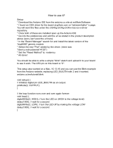
Go to the Snapino
TM
product page (www.snapcircuits.net/scsnapino) and download
the Snapino
TM
program files from our website to your computer. In the File menu in
the Arduino IDE, pick Open, then go to where you downloaded the Snapino
TM
program files to, and pick the Blinking_Light program or “sketch” (Arduino users
refer to a program as a sketch). The sketch should appear in the IDE window, as
shown below.
Now download the program into the Snapino
TM
module. Click on the Upload button
in the IDE.
The blue status bar near the bottom should indicate that the upload is occurring,
and when it is done. Two LEDs should now be blinking - a small yellow LED on
the UNO board (usually marked “L”) and the green LED (D2) in Snap Circuits
®
.
You can now disconnect the USB cable and connect the 9V battery holder. Turn
on the switch on the 9V battery holder, and the sketch will begin running.
Note: Snapino
TM
does not have an on/off switch when powered using the USB
cable. To turn it off, disconnect the USB cable from your computer.
Troubleshooting:
If there was a problem with the upload, then the status bar would be orange, indicating a problem.
If you had unplugged the USB cable and it does not recognize the module when
USB is connected again, then you may need to re-select the port. In Tools, select
Port, then pick the one that shows an Arduino UNO (Windows users) or either of
the following: /dev/tty/usbmodem or /dev/cu.usbmodem5dll (Mac users).
SCSNAPINO_Manual_112816.qxp 12/30/16 2:00 PM Page 16

Learn About Programming
Here is how the sketch works:
void - this sets up a function.
setup - this is a function that initializes variables, pin modes,
etc.
pinMode(13, OUTPUT) - this configures digital pin 13 to act
as an output.
loop - this is a function for executing the following
commands in a continuous loop.
digitalWrite(13, HIGH) - this tells Snapino
TM
to put an
electrical voltage at digital pin 13 (where the Snap Circuits
®
green LED (D2) is connected). This voltage will light the
LED. A small yellow LED on the UNO circuit board also
lights; this LED is permanently connected to digital pin 13.
delay(500) - this tells Snapino
TM
to pause for 500
milliseconds, or 0.5 second, before performing the next
instruction.
digitalWrite(13, LOW) - this tells Snapino
TM
to turn off or
remove any voltage at digital pin 13. This will turn off the
green LED (and the yellow LED on the UNO board).
Comments: All information after // is Comments. Comments
are a description of what the sketch is doing, to help you
understand and remember it. Comments are automatically
removed before the sketch is downloaded to Snapino
TM
.
-16-
You can edit the sketch to change parameters or commands if
desired. The editing procedure is similar to other word
processors. You may also type in a completely new sketch. To
save sketches you have created or modified, use
Save As under
File menu.
Only valid sketches (without errors) may be downloaded, or a
downloading error will result. You can check for errors by clicking the
Verify box. Verify also tells you how much memory the sketch uses.
Explanations for all Arduino commands, and some basic
information about programming, can be found under the
Help
menu or on the Arduino website (www.arduino.cc).
You can change the blink rate by changing the delay value from 500 to
something else. Try 200 (faster blinking) or 2000 (slower blinking). Change the
value at both locations in the sketch, then upload the sketch into Snapino
TM
.
SCSNAPINO_Manual_112816.qxp 12/30/16 2:00 PM Page 17

-17-
Alternating Lights
Project 4
Build this circuit. Load sketch Alternating_Lights into
Snapino
TM
using the programming instructions in project 3.
Arduino controls the two Snap Circuits
®
LEDs (red and
green), and alternates turning them on and off.
Programming Note:
This sketch uses the int command (int is short for integer)
to assign a constant value that will be used within the
sketch. You can change the blink rate by editing the delay
value, then reloading it into Snapino
TM
.
The microcontroller on the Arduino UNO board lets you
control the LEDs in ways that would be difficult to do using
switches or other devices.
SCSNAPINO_Manual_112816.qxp 12/30/16 2:00 PM Page 18

YELLOW
-18-
Stoplight
Project 5
Build this circuit. Load sketch Stoplight into Snapino
TM
using
the programming instructions in project 3. Snapino
TM
controls the three Snap Circuits
®
LEDs (green, yellow, and
red), and turns them on and off like a stoplight. The yellow
light is only on for half as long, just like a normal stoplight.
Programming Note: This sketch uses
the int command to assign constant
values for the delay and LED connection
pins. Doing this makes them easy to
change later, because you would only
need to change them in one place,
instead of throughout the sketch. You can
change the blink rate by editing the delay
value, then reloading it into Snapino
TM
.
SCSNAPINO_Manual_112816.qxp 12/30/16 2:00 PM Page 19

-19-
Button
Project 6
Build this circuit. Load sketch Button into Snapino
TM
using
the programming instructions in project 3. The red LED (D1)
should be on; push the press switch (S2) to turn it off.
Swap the locations of the press switch and 10KW resistor
(R4). Now the red LED turns on when the press switch is
pushed.
Programming Note:
This sketch monitors the voltage between the 10KW resistor and
press switch; normally the resistor pulls the voltage high, but
pushing the switch pulls it low. Snapino
TM
monitors the voltage and
turns off the red LED when it receives a low signal from the button.
If the button is released, then the monitored voltage will go back to
high, and Snapino
TM
turns on the red LED.
digitalRead(button) - this command tells Snapino
TM
to read the
voltage at button (which had been assigned as digital pin 9), and
assign it to variable buttonState.
SCSNAPINO_Manual_112816.qxp 12/30/16 2:00 PM Page 20
/