Samsung MCM-A300N Installation guide

Type
Installation guide

This manual is also suitable for

Touch Centralized Controller
MCM-A300N
Air Conditioner
installation manual
imagine the possibilities
Thank you for purchasing this Samsung product.
DB68-03943A-03
EN ES FR IT PT DE EL RU TR AR
Touch-controller_IM_DB68-03943A_03_EN.indd 1 2016-04-27 오후 3:59:08
2
Safety precautions
This installation manual is for installing the Touch Centralized Controller. Read the installation manual thoroughly before
installing the product. (Refer to the appropriate manual for installing other optional parts.)
WARNING
• Hazards or unsafe practices that may result in severe personal injury or death.
CAUTION
• Hazards or unsafe practices that may result in minor personal injury or property damage.
SEVERE WARNING SIGNS
Consult qualied installer or service center for installation.
There is a risk of product malfunction, water leakage, electric shock or re.
Install the product rmly on the place that can withstand the weight of the product.
If the installation location is not strong enough, product may fall and get damaged.
Connect the power with rated voltage when installing.
If not, there is risk of re or damage to the product.
Do not attempt to move or re-install the product that is already installed.
There is risk of electric shock and re.
Do not attempt to repair, disassemble, or modify the product yourself.
There is potential risk of product damage, electric shock or re. When repair is needed, consult qualied installer or
service center.
Check if the installation was done properly according to the installation manual.
There is risk of electric shock or re if the product is installed incorrectly.
Make sure that all wiring work is done by qualied person complying regional standards and instructions in this
manual.
If the installation is done by unqualied person, there is risk of product malfunction, electric shock or re caused by
incorrect installation.
Contact the service center when you need to dispose the product.
Touch-controller_IM_DB68-03943A_03_EN.indd 2 2016-04-27 오후 3:59:08
3
ENGLISH
CAUTION SIGNS
Do not install the product in a place where it is or might be exposed to inammable gas leakage.
There is risk of re or explosion.
Do not install the product in a place where it will be exposed to oil or vapor etc.
If the product is used in a place where it is exposed to oil, vapor or sulphur dioxide, parts of the product may get
damaged or product may function abnormally.
Make sure that water does not get into the product.
There is risk of electric shock and re.
Make sure there is no tension to the cable during installation.
Cable may get cut and cause re.
Install the product in a place with temperature between 0 °c~39 °c with no direct sunlight.
There is risk of electric shock or abnormal operation.
Do not install the product in a place where special spray or acid/alkali solution is used.
There is risk of electric shock or abnormal operation.
Do not press the button with sharp object.
There is risk of electric shock or damaging the parts.
Do not connect the power cable to the communication cable terminal.
There is risk of re or explosion.
When installing the product in hospitals or other places, make sure that the product does not interrupt with other
products.
Abnormal operation may occur.
Touch-controller_IM_DB68-03943A_03_EN.indd 3 2016-04-27 오후 3:59:09
4
Before installation
Check list before the installation
Installation cables
Cables must be installed not to tightly to the wall where the product will be installed in prior to product installation.
Accessories
Before the installation, check if all the accessories are included with the product. Type and quantity of the accessories
may be subject to change without prior notice.
Name
Touch Centralized
Controller
Cable tie M4 Screw User's manual
Installation
manual
Quantity 1 3 4 1 1
Image
• Touch Centralized Controller must be installed by the installation expert.
• Before installing the Touch Centralized Controller, check if the power is o.
• Communication cable must be installed according to the electrical wiring regulation and make sure that cable is
installed through the wall so that it is not exposed to the users. (Use VCTF 2C х 0.75 mm
2
Communication cable )
CAUTION
Touch-controller_IM_DB68-03943A_03_EN.indd 4 2016-04-27 오후 3:59:09
5
ENGLISH
Selecting solderless ring terminal
1. Select a solderless ring terminal for a power cable according to the nominal dimensions for cable.
2. Apply insulation coating to the connection part of the solderless ring terminal and the power cable.
Silver solder
Nominal dimensions for cable (mm
2
) 1.5 2.5
Nominal dimensions for screw (mm) 4 4 4 4
B
Standard dimension (mm) 6.6 8 6.6 8.5
Allowance (mm) ±0.2 ±0.2
D
Standard dimension (mm) 3.4 4.2
Allowance (mm)
+0.3
-0.2
+0.3
-0.2
d1
Standard dimension (mm) 1.7 2.3
Allowance (mm) ±0.2 ±0.2
E Min. (mm) 4.1 6
F Min. (mm) 6 6
L Max. (mm) 16 17.5
d2
Standard dimension (mm) 4.3 4.3
Allowance (mm)
+ 0.2
0
+ 0.2
0
t Min. (mm) 0.7 0.8
Touch-controller_IM_DB68-03943A_03_EN.indd 5 2016-04-27 오후 3:59:09
6
Name of the parts and product dimensions
Name of the parts
Front
Touch Centralized Controller
Control &
Monitoring
Schedule Setting
SD card slot
LCD ON/OFF button
Indoor unit operation lamp (Blue)
Error lamp (Red)
Bottom
Power terminal
DI-1 terminal
Reset Button
DI-2 terminal
RS 485 communication terminal
DO Terminal
Touch-controller_IM_DB68-03943A_03_EN.indd 6 2016-04-27 오후 3:59:09
7
ENGLISH
Product dimensions
205
170
(Unit : mm)
163
38141
Touch-controller_IM_DB68-03943A_03_EN.indd 7 2016-04-27 오후 3:59:09
8
Installing the Touch Centralized Controller
System diagram
S-NET 3
TCP/IP
DMS2
Touch Centralized Controller
OnO controller
Outdoor unit
RS 485
Maximum 128 indoor units
(DVM series)
Checking the power connection
1. Press the LCD ON/OFF button to turn on the LCD.
2. Check if the LCD turns on.
- If the LCD does not turn on, check the connection of the power(AC 100~240 V, 50/60 Hz) terminal and the power
connector.
Checking the LED
1. There is an error If the Error lamp (Red) turns on.
2. If the Error lamp (Red) turns on, check the connection status of communication/power and the status of communication
cable.
3. If the Error lamp (Red) turns on, check if there is any error on the indoor unit that is connected to the Touch Centralized
Controller.
Maximum allowable number of connections
Classication When connected to control device layer When connected to indoor/outdoor unit layer
Outdoor unit 16 units 1 unit
Indoor unit / ERV 128 units 80 units
Touch-controller_IM_DB68-03943A_03_EN.indd 8 2016-04-27 오후 3:59:10
9
ENGLISH
Installing the Touch Centralized Controller
1. Fix the installation plate of the Touch Centralized Controller on the wall with 4screws.
2. Connect the power cable to the power terminal on the back of the Touch Centralized
Controller.
Tightening torque (N.m)
M4 1.2~1.5
[Arranging the wire in
downward direction]
[Arranging the wire in
upward direction (for
in-wall wiring)]
Power cable
Communication cable
Fix it rmly with a
cable tie
When the wire needs to be arranged in upward direction,
cut part of the case (as indicated in below illustration)
by using an appropriate tools. (When cutting the part
of the case, length and width should not exceed the
measurements stated in the illustration)
Max 39.0
Max 7.0
Part to be cut
3. Connect the communication cable to the 485 communication terminal on the back of the Touch Centralized Controller.
- If the connection is not done properly, communication may not work properly.
- Use appropriate tools to connect the cables rmly within rated torque range so that it can withstand external forces.
- You may connect the communication cable of the F1, F2 terminal of the indoor/outdoor unit or R1, R2 of the outdoor
unit.
- When connecting the Touch Centralized Controller to indoor/outdoor unit layer use F1, F2 terminal and use R1, R2
terminal when connecting it to control device layer.
4. Hang the top part of the Touch Centralized Controller on the installation plate, already installed on the wall, and fasten
the hooks on the bottom part of the installation plate.
- Make sure to x the Touch Centralized Controller rmly since it may fall to the ground and get damaged if it is not rmly
xed.
Disassemble point
To separate the product from the installation plate
Grooves for the hooks (inside the installation plate)
To x the product to the installation plate
Installation plate
• It is recommended to install the product on the wall for safe use and to prevent it from troubles and damages.
CAUTION
Touch-controller_IM_DB68-03943A_03_EN.indd 9 2016-04-27 오후 3:59:10
10
Installing the Touch Centralized Controller
Tracking
Through tracking function, Touch Centralized Controller searches for the device that forms a system and registers the
installation & status information of those devices.
1. When you go to [Setting] [Installation settings] [Network & Tracking] menu and tap [Tracking] button, tracking will
begin after user authentication.
2. Tracking will run for maximum 10 minutes.
- If the number of connected outdoor unit increases, it may take long time for tracking.
3. When the tracking is done, you can check the list of searched devices.
4. You can select Show/Hide (
) for the device that has completed the tracking.
- You can also hide the device which is found during the tracking with the Hide function.
5. Indoor units that has disabled centralized control option will be xed to 'Hide' status and it cannot be changed.
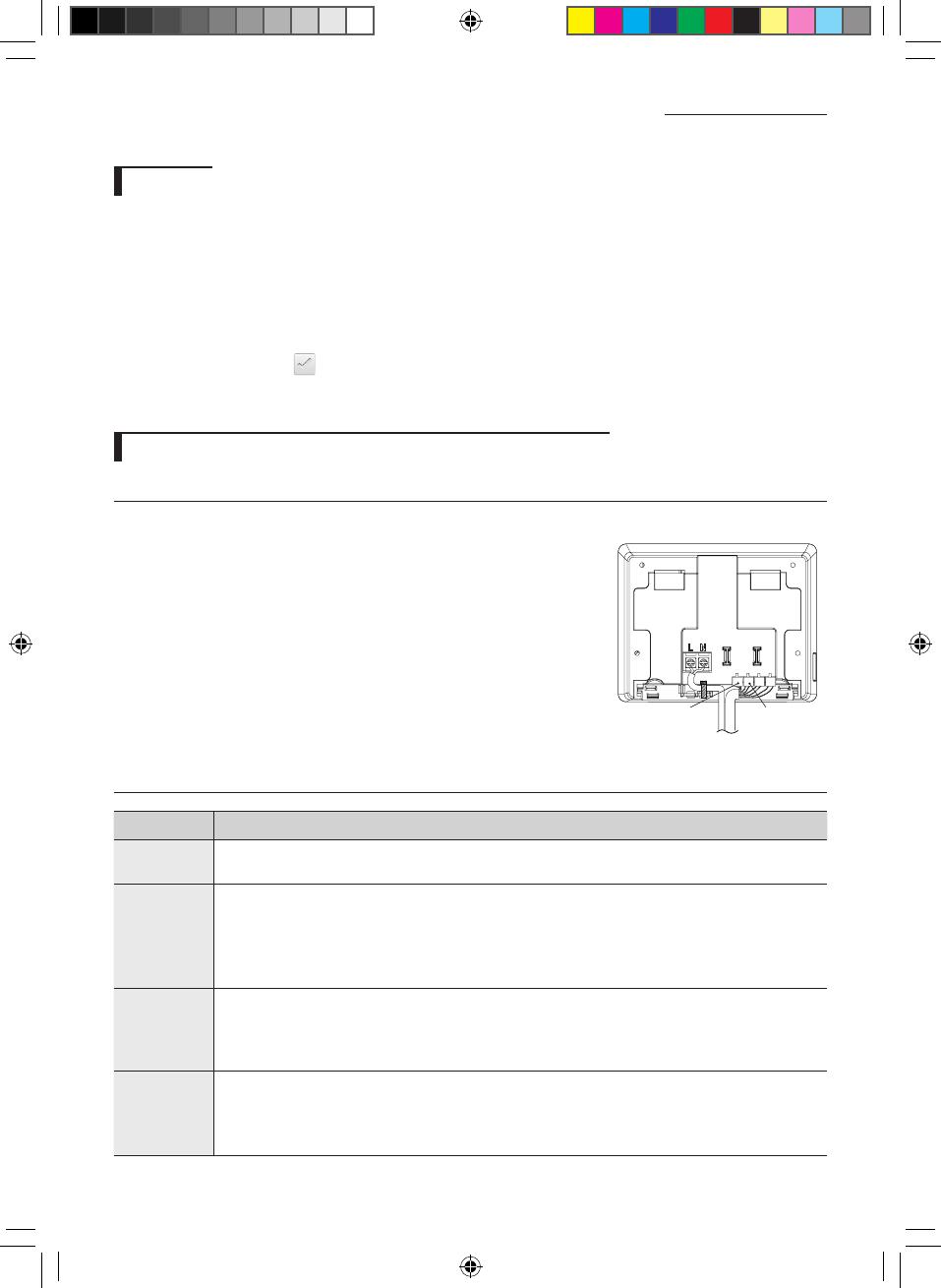
Setting for external contact control through DI port (Optional)
Setting DI pattern
You can set the DI pattern from [Setting] [System settings] [DI pattern] menu.
DI port
Dry contact must be connected.
DI-1 (+,-) DI-2 (+,-)
Control pattern
Pattern Description of control
1
• No external input (Factory default setting)
• Nothing will happen when contact signal is inputted to port 1.
2
• When DI-1 ON signal is input, emergency stop status will occur.
• It will stop all indoor units and order the indoor units not to be controlled by a remote controller.
• In the emergency stop status, you cannot use the user control command. In addition, the schedule
control will not work. When the contact control signal is changed to OFF, the control command can
work normally. (DI-2 will not be used with the pattern 2)
3
• When DI-1 ON signal is input, it will stop all indoor units. When OFF signal is input, all indoor units are
ON.
• When DI-2 ON signal is input, the remote control status of all the indoor units will be enabled and when
the OFF signal is input, the remote control status will be disabled.
4
• Valid pulse width of the input signal is between 0.5~1.0 second. Signals with pulse width below 0.5 and
over 1.0 second will be ignored.
• When the pulse contact signal is input to DI-1, ON command will be sent to all indoor units.
• When the pulse contact signal is input to DI-2, OFF command will be sent to all indoor units.
Touch-controller_IM_DB68-03943A_03_EN.indd 10 2016-04-27 오후 3:59:11
11
ENGLISH
DO port
DO operation specication
DO output will turn on if any one of the indoor unit is turned on. DO output will
turn o if all the indoor units are turned o.
DO port
(+)terminal outputs 12 V, (-) terminal outputs open collector, Drive current
under 10 mA.
DO (+,-)
Touch-controller_IM_DB68-03943A_03_EN.indd 11 2016-04-27 오후 3:59:11
Touch-controller_IM_DB68-03943A_03_EN.indd 12 2016-04-27 오후 3:59:11
  • Page 1 1
  • Page 2 2
  • Page 3 3
  • Page 4 4
  • Page 5 5
  • Page 6 6
  • Page 7 7
  • Page 8 8
  • Page 9 9
  • Page 10 10
  • Page 11 11
  • Page 12 12

Samsung MCM-A300N Installation guide

Type
Installation guide
This manual is also suitable for

Ask a question and I''ll find the answer in the document

Finding information in a document is now easier with AI