10
English
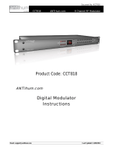
Using the Smart Touch Control
TV
MIC
STB
SOURCE
VOICE
MORE
SMART HUB
GUIDERETURN
EXIT
HOME
Touch Pad
• Drag on the Touch Pad to move the focus
on the screen.
• Press the Touch Pad to run, activate, or
select the highlighted item.
• Press and hold the touch pad to display
the Channel List.
VOICE˜
Take your voice command and enter a text
using your voice.
You can use the MIC to give Voice Recognition commands. Simply press the VOICE˜ button.
✎
Voice Recognition function can be affected by unclear pronunciation, voice level, or
surrounding noise.
Displays a virtual remote control on the screen.
Press and hold the touchpad to select a
desired function (e.g. MENU (m),
TOOLS (T), INFO (`), etc.) easily.
Changes channels.
View each digital channel's programming
schedule, including showtimes. In addition,
sets a Schedule Viewing or Schedule
Recording to press the touch pad on the
programme entry scheduled to air later.
Turn on and off the satellite or cable set-top
box connected to the TV.
Turns the TV on and off.
Displays and selects the available video
sources.
Adjusts the volume.
Cuts off the sound
temporarily.
Press and hold this button
to select Audio Description
and Subtitle. (Depending
on the country or region.)
Returns to the previous menu. Press and
hold this button to exit all currently running
applications.
Brings up Smart Hub applications.
✎
To exit an application that is running,
press the ™ button.
TV
MIC
STB
SOURCE
VOICE
MORE
SMART HUB
GUIDERETURN
EXIT
MUTE
HOME
The colour buttons work differently,
depending on the function that the TV is
currently performing.
Press and hold the { button while
watching TV to view information about the
current programme.
Only Used in Widget Mode.
Connecting to the TV
In order to operate the TV using a Smart Touch Control unit, you must fi rst pair it to the TV via Bluetooth.
However, the Smart Touch
Control is only available for the paired Samsung TV.
1. When the TV is off, point the Smart Touch Control at the remote control receiver of the TV and press the TV button for the fi rst
pairing. Only this buttons sends an IR signal. The remote control receiver's location may vary depending on the model.
2. A Bluetooth icon will appear at the bottom left of the screen as shown below. The TV will then attempt to connect to the Smart Touch
Control unit automatically.
<Attempting to connect and completion icons>
[HB890-EUROPE-46 55 65]Install Guide.indb 10 2013-04-29 9:41:50