Page is loading ...

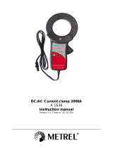
Flex current clamps
A 1179
A 1257
A 1395
User Manual
Version 1.6; Code No. 20 751 167
KOMETEC Karl Oelkers e.K.
Mess- und Prüfgeräte · Shop
Mozartstr. 10 · D-88097 Eriskirch
T: 07541 / 955-1313 · F: 07541 / 955-1131
[email protected] · www.kometec.de

2
Distributor:
Producer:
METREL d.d.
Ljubljanska 77
SI-1354 Horjul
Tel.: +386 1 75 58 200
Fax: +386 1 75 49 226
E-mail: [email protected]
http://www.metrel.si
Mark on your equipment certifies that this equipment meets the requirements
of the EC (European Community) regulations concerning safety and
electromagnetic compatibility.
© 2007, 2008, 2012 Metrel
No part of this publication may be reproduced or utilized in any form or by any means
without permission in writing from METREL.

A 1179, A 1257, A 1395 Flex current clamps
3
Table of contents
1 Introducing the A1179/A1257/A1395 ........................................................................ 4
2 Features ................................................................................................................... 4
3 Safety ....................................................................................................................... 5
4 Symbols .................................................................................................................... 6
5 Output connecting ..................................................................................................... 6
6 Using A1179/A1257/A1395 Flexible Current Clamps ............................................... 7
6.1 Battery and charging ........................................................................................... 7
6.1.1 New battery cells or cells unused for a longer period.................................... 7
6.2 User interface ..................................................................................................... 8
6.2.1 A1179/A1257/A1395 states regarding power supply .................................... 9
6.2.2 A1179/A1257/A1395 states regarding measuring ranges ........................... 10
7 Measuring current with A1179/A1257/A1395 .......................................................... 12
8 Cleaning .................................................................................................................. 13
9 Service .................................................................................................................... 13
10 Technical specifications .......................................................................................... 14

A 1179, A 1257, A 1395 Flex current clamps
4
1 Introducing the A1179/A1257/A1395
The A1179/A1257 (A1179 has measuring ranges 20A/200A2000A, A1257 has
measuring ranges 30A/300/3000A) Flexible Current Clamps consist of three flexible
sensors and an electronic module. The A1395 has measuring ranges 30A/300/3000A
and two flexible sensors and an electronic module.
A current measurement can be carried out on the two/three phases
simultaneously, with a suitable output voltage for the Measuring ANALYZER /
Multimeter. The flexible sensor permits measurements on conductors where standard
clamp-on current transformers can not be used. It is particularly useful for installation in
tight spaces, or around breaker panels, cable bundles, wide or large bus bars and
irregular shapes. Unlike standard current transformers, this flexible CP does not use
magnetic cores. The transformation principle is based on an air core. It presents
virtually no load to the system under test, has a low phase shift and excellent frequency
response.
The electronic module can detect if the measured current amplitude is too big for
the selected range (crest factor of the amplifier is 3.0). This overrange detection is
indicated by a blinking range LED diode for currently selected range. If the overrange
current was detected but is not currently present, the user can reset the blinking Range
LED by pressing the key. If the overrange is present also when the key is pressed, the
range will be changed to the less sensitive range. The electronic module has low
battery indication as well.
Additionally, A1179/A1257/A1395 cannot be damaged by overloads. The
A1179/A1257/A1395 Flexible Current Clamps are insensitive to DC current and
measure only the AC component of the measured signal.
2 Features
Direct connection to 1V AC input on measuring device, and optional connection to
other meters (data logger, multi-meters,etc.),on demand
Switch ON, switch OFF and two/three measuring ranges with one key selection
(2000/3000 Arms, 200/300 Arms and 20/30 Arms)
Overrange indication for measurement circuitry (blinking LED at corresponding
range)
mV output
Waterproof sensor
Minimum angle shift to accomplish accurate power measurements
High accuracy
Simultaneous measurement of the two/three phases
Total rejection of d.c.component
Friendly-use of the closing-opening system of the current sensor (even if wearing
gloves) due to its highly ergonomic design
It is possible to set the seal on the closing system of the current clamp.
Very light, flexible and fully adaptable to busbar trunking system and insulated
cables
Strengthened security, regardless the working environment:industrial or services
Possibility of external power supply at 220 V a.c./12 V d.c.
Build in charger (Low Bat LED on)
Low battery indication (blinking Low Bat LED)

A 1179, A 1257, A 1395 Flex current clamps
5
3 Safety
Read the operating instructions before use and follow all safety instructions.
If the test equipment is used in a manner that is not specified in this user manual,
the protection provided by the equipment might be impaired!
Adhere to local and national safety codes. Individual protective equipment must
be used to prevent shock and arc blast injury where hazardous live conductors
are exposed.
Before each use, inspect the Current Clamps and its latching system for any
damage. Pay particular attention to the insulation surrounding the flexible
measuring head. Look for cracks or missing portions of the clamp housing or
output cable insulation. Also look for loose or weakened components.
Do not use a clamp that is cracked, damaged, or has a defective cable.
Never use the clamp on a circuit with voltages higher than 1000 V CAT III or
600V CAT IV.
De-energize the installation on which current will be measured or adopt safe
operating procedures during application and removal of the current clamp.
Use extreme caution when working around bare conductors or bus bars.
Do not use the Current Clamp to measure bare conductors carrying a voltage
from 30V up to 1000V unless you are wearing protective clothing suitable for
high-voltage work. Contact with the conductor could result in electric shock.
Always use appropriate equipment for personal protection.
Use caution when working with voltages above 60 V dc, 30 V ac rms or 42 V ac
peak. Such voltages pose a shock hazard.
Do not expose the A1179/A1257/A1395 unit to water.

A 1179, A 1257, A 1395 Flex current clamps
6
4 Symbols
Symbol Description
Inportant information. Refer to the manual.
Risk of Electric Shock.
Product is protected by Double/Reinforced insulation
Do not apply around or remove from HAZARDUS LIVE conductors.
Do not dispose of this product as unsorted municipal waste. Contact
Metrel or a qualified recycler for disposal.
Complies with the relevant European standards.
5 Output connecting
The A1179/A1257/A1395 Flexible Current Clamps can be used with any Metrel
Power Analyzer, Oscilloscope, or Multimeter that has the following features:
D01 3 Pin Receptacle Panel Mount input connector or appropriate adapter.
Input accuracy of 1% or better to take full advantage of the accuracy of the Current
Clamps.
Input impedance of greater than or equal to 10 kΩ, and for full bandwidth and
accuracy, a maximum input capacity of 100 pF.
A pass band of more than four times the frequency of the waveform to be measured.

A 1179, A 1257, A 1395 Flex current clamps
7
6 Using A1179/A1257/A1395 Flexible Current
Clamps
6.1 Battery and charging
The A1179/A1257/A1395 uses two AA size alkaline or rechargeable Ni-Cd or Ni-
MH battery cells. Nominal operating time is declared for cells with nominal capacity of
2200 mAh. In case the battery is weak, the A1179/A1257/A1395 indicates this with Low
bat LED blinking.
The battery is charged whenever the power supply adapter is connected to the
A1179/A1257/A1395. Internal circuit controls charging assuring maximum battery
lifetime. Power supply socket polarity is shown in Picture 6.1.
+
-
Picture 6.1: Power supply socket polarity
The A1179/A1257/A1395 automatically recognizes connected power supply adapter
and controls charging. After 24 hours of continuous charging it is switched off.
Before opening battery compartment cover disconnect all measuring
accessories connected to the clamps and power off the A1179/A1257.
Insert cells correctly, otherwise the A1179/A1257/A1395 will not operate and the
battery could be discharged.
Remove all battery cells from the battery compartment if the
A1179/A1257/A1395 is not used for longer period.
Do not charge alkaline battery cells!
Take into account handling, maintenance and recycling requirements that are
defined by related regulatives and manufacturer of alkaline or rechargeable
batteries!
Use only power supply adapter delivered from manufacturer or distributor of the
test equipment to avoid possible fire or electric shock!
Do not use battery cells with different capacity.
6.1.1 New battery cells or cells unused for a longer period
Unpredictable chemical processes can occur during charging of new battery cells
or cells that were unused for a longer period (more than 3 months). Ni-MH and Ni-Cd
battery cells are affected to capacity degradation (sometimes called as memory effect).
As a result, the A1179/A1257/A1395 operation time can be significantly reduced.
Recommended procedure for recovering battery cells:

A 1179, A 1257, A 1395 Flex current clamps
8
Procedure Notes
Completely charge the battery.
Time depends on the battery capacity
(10 – 24 hours)
Completely discharge the battery.
Can be performed with normal work with
the A1179/A1257/A1395.
Repeat the charge / discharge cycle
for at least two times.
Four cycles are recommended.
Complete discharge / charge cycle is performed automatically for each cell using
external intelligent battery charger.
Notes:
The charger in the A1179/A1257/A1395 is a pack cell charger. This means that
the battery cells are connected in series during the charging. The battery cells
have to be equivalent (same charge condition, same type and age).
One different battery cell can cause an improper charging and incorrect
discharging during normal usage of the entire battery pack (it results in heating of
the battery pack, significantly decreased operation time, reversed polarity of
defective cell,…).
If no improvement is achieved after several charge / discharge cycles, then each
battery cell should be checked (by comparing battery voltages, testing them in a
cell charger, etc). It is very likely that only some of the battery cells are
deteriorated.
The effects described above should not be mixed with normal decrease of
battery capacity over time. Battery also loses some capacity when it is
repeatedly charged / discharged. Actual decreasing of capacity, versus number
of charging cycles, depends on battery type. It is provided in the technical
specification from battery manufacturer.
6.2 User interface
Power LED
Range LEDs
{
KEY
Picture 6.2: Front user interface view for A1179

A 1179, A 1257, A 1395 Flex current clamps
9
Range LEDs: one of these LEDs indicates corresponding measuring range of the
output signal. If the LED is blinking (1 s ON – 1s OFF)
A1179/A1257/A1395 detect overrange event at the currently selected
range. With pressing the KEY one can reset overrange detection. If all
Range LEDs are OFF it indicates power off the A1179/A1257/A1395.
Power LED: OFF – normal operation
Blinking (1 s ON – 1s OFF) – low battery indication, the battery is too
weak for correct measurement results.
ON – The battery cells are charged.
KEY: Turns the A1179/A1257/A1395 ON, change the measuring range, reset
overrange detection, if held in for more then 3 seconds it turns the
A1179/A1257/A1395 module OFF.
See detailed description of A1179/A1257/A1395 operating states in chapter 6.2.1 and
6.2.2.
6.2.1 A1179/A1257/A1395 states regarding power supply
The use of the A1179/A1257/A1395 module is very easy and intuitive. In
following tables (Table 6.1 and Table 6.2) the A1179/A1257/A1395 module states
regarding power supply and charging and actions to change between them are defined.
State How is it indicating? What is happening?
POWER OFF All LED diodes OFF, External
power supply is not connected.
A1179/A1257/A1395 is not
working. Battery is not charged.
NORMAL One of the Range LED is ON, Low
bat is OFF .
A1179/A1257/A1395 is working
from the battery. Battery is not
charged.
EXTERNAL
NORMAL
Low bat LED is ON, External
power supply is connected and
batteries are not present.. One of
the Range LED is ON.
A1179/A1257/A1395 is working
from the external power supply.
Battery is not charged.
LOW
BATTERY
Low bat LED is blinking. A1179/A1257/A1395 is working.
Battery is low, Measuring results
may not be in specifications.
Battery is not charged.
CHARGE +
NORMAL
One of the Range LED is ON, Low
bat is ON External power supply is
connected and rechargable
batteries are present.
Battery is charged.
A1179/A1257/A1395 is powered
from external power supply (not
from batteries).
CHARGE All Range LEDs are OFF. Low bat
is ON External power supply is
connected and rechargable
batteries are present.
Battery is charged. No
measuring is possible.
Table 6.1 Power supply state indications

A 1179, A 1257, A 1395 Flex current clamps
10
State before Action to change the state New state
POWER OFF Press the key NORMAL
POWER OFF Connect external power supply CHARGE
NORMAL Ubat < 2.1 V LOW BATTERY
NORMAL Connect external power supply CHARGE + NORMAL
LOW BATTERY Connect external power supply CHARGE + NORMAL
NORMAL Long press the key POWER OFF
CHARGE + NORMAL Long press the key CHARGE
EXTERNAL
NORMAL
Long press the key POWER OFF
POWER OFF Insert the batteries into the battery
compartment
POWER OFF
CHARGE Press the key CHARGE + NORMAL
Table 6.2 Allowed change state table regarding power supply
6.2.2 A1179/A1257/A1395 states regarding measuring ranges
Changing of the measuring range is done just by pressing the key. After switch
ON (also by pressing the key) module is at 20/30 A range. If you pressing the key again
the 200/300 A range is selected etc. (see Table 6.4).
A1179/A1257/A1395 module has overrange current detection as noted in
chapter 1. It means that A1179/A1257/A1395 module informs the user if the selected
range is too small for measured current amplitude (peak value). If the overrange current
was detected but currently it is not present any more the user can reset blinking Range
LED by pressing the key (see Table 6.5). If the overrange is present also when the key
is pressed the range will be changed to the less sensitive range (see Table 6.6).
State indications:
State How is it indicating? What is heppening?
RANGE
2000/3000 A
2000/3000 A Range LED diode is
ON. Others are OFF.
A1179/A1257/A1395 is working
on 0.5/0.333mV/A rms range.
RANGE
200/300 A
200/300 A Range LED diode is
ON. Others are OFF
A1179/A1257/A1395 is working
on 5/3.33mV/A rms range.
RANGE 20/30 A 20/30 A Range LED diode is ON.
Others are OFF
A1179/A1257/A1395 is working
on 50/33.3mV/A rms range.
OVERRANGE
DETECTION
20/30 A
20/30 A Range LED diode is
blinking.
A1179/A1257/A1395 has
detected an overrange at 20/30
A range.
OVERRANGE
DETECTION
200/300 A
200/300 A Range LED diode is
blinking.
A1179/A1257/A1395 has
detected an overrange at
200/300 A range.
OVERRANGE
DETECTION
2000/3000A
2000/3000 A Range LED diode is
blinking.
A1179/A1257/A1395 has
detected an overrange at
2000/3000 A range.
Table 6.3 Range state indications
State before Action to change state New state

A 1179, A 1257, A 1395 Flex current clamps
11
POWER OFF press the key RANGE 20/30 A
RANGE 20/30 A press the key RANGE 200/300 A
RANGE 200/300 A press the key RANGE 2000/3000 A
RANGE 2000/3000 A press the key RANGE 20/30 A
Table 6.4: Change range state table
State before Action to change
state
New state
RANGE 20/30 A Single overrange OVERRANGE DETECTION
20/30 A
OVERRANGE DETECTION
20/30 A
Press the key RANGE 20/30 A
RANGE 200/300 A Single overrange OVERRANGE DETECTION
200/300 A
OVERRANGE DETECTION
200/300 A
Press the key RANGE 200/300 A
RANGE 2000/3000 A Single overrange OVERRANGE DETECTION
2000/3000 A
OVERRANGE DETECTION
2000/3000 A
Press the key RANGE 2000/3000 A
Table 6.5: Change state table when single overrange is detected
State before Action to change
state
New state
RANGE 20/30 A Permanent
overrange
OVERRANGE DETECTION
20/30 A
OVERRANGE DETECTION
20/30 A
Press the key RANGE 200/300 A
RANGE 200/300 A Permanent
overrange
OVERRANGE DETECTION
200/300 A
OVERRANGE DETECTION
200/300 A
Press the key RANGE 2000/3000 A
RANGE 2000/3000 A Permanent
overrange
OVERRANGE DETECTION
2000/3000 A
OVERRANGE DETECTION
2000/3000 A
Press the key *RANGE 20/30 A
*This is yust for indication that permanent overrange exists. You should use clamps
with higher upper current limit.
Table 6.6: Change state when permanent overrange is detected

A 1179, A 1257, A 1395 Flex current clamps
12
7 Measuring current with A1179/A1257/A1395
I
1
2
Picture 7.1: Wrap the measured cable with the measuring clamp
To use the A1179/A1257/A1395 Flexible Current Clamps, follow these instructions:
1. Connect the D01 3 Pin connector of the A1179/A1257/A1395 Flexible Current
Clamps to the desired input on the measuring instrument (power meter, digital
multimeter, oscilloscope,…) .
2. On the A1179/A1257/A1395 Flexible Current Clamps unit, select the least sensitive
range (set the range to ‘2000/3000 A’ – 0.5/0.333 mV/A).
3. Select the corresponding sensitivity (.. mV/A) on your instrument. If you are using a
multimeter, select an appropriate AC voltage range.
4. Wrap the flexible measuring head around the conductor to be tested, close coupling
(See Picture 7.1 ).
5. It is very important that the conductor is as the center and perpendicular to the
measuring head. (if it is no possible additional error of 2% of full scale can occur).
6. Do not measure close to other current-carrying conductors if possible. (An external
field of 40 A/m can cause an additional measurement error of 1% of full scale).
7. Make sure that the arrow marked on the clamp coupling points toward the correct
orientation for correct phase display on the oscilloscope. (See Picture 7.1 )
8. Keep the clamp coupling more than 2.5 cm (1 inch) away from the conductor to be
tested and other nearby conductors.
9. Observe the current value and waveform on the instrument’s display. If desired,
select the lower range on the A1179/A1257/A1395 module and set the
corresponding sensitivity on the measurement instrument. If the A1179/A1257/A1395
is used with a multimeter, the actual current value can be calculated from the
displayed AC voltage value.

A 1179, A 1257, A 1395 Flex current clamps
13
8 Cleaning
Use soft patch, slightly moistened with soap water or alcohol, to clean the surface
of the A1179/A1257/A1395 and leave it to dry totally, before using it.
Do not use liquids based on petrol or hydrocarbons!
Do not spill cleaning liquid over the A1179/A1257/A1395!
9 Service
For repairs under or out of warranty time please contact your Metrel distributor for
further information.
Name and address of manufacturer:
METREL d.d.
Ljubljanska cesta 77
SI-1354 Horjul
Tel.: +386 1 75 58 200, fax.: +386 1 75 49 226, +386 1 75 49 206
http://www.metrel.si
E-mail: [email protected]

A 1179, A 1257, A 1395 Flex current clamps
14
10 Technical specifications
FEATURES NOTES DESCRIPTION
Length of the sensor
48 cm
Measuring range A1179
20 A / 200 A / 2000A ac rms
Measuring range
A1257/A1395
30 A / 300 A / 3000A ac rms
Overscale A1179
40A / 400A / 4000 A sinus
Overscale A1257/A1395
60A / 600A / 6000 A sinus
Sensitivities A1179
50 mV / A; 5 mV / A; 0.5 mV / A
Sensitivities A1257/A1395
33.3 mV / A; 3.33 mV / A; 0.333 mV / A
Bandwidth 1
10 Hz up to 8 kHz
Accuracy 2,3,4
+/-1 %
Linearity (10 % to 100 %) 2,3,4
+/-0,2 %
Position sensitivity 6
+/-2 % of full scale
Temperature dependency 9
+/-0.02 % of reading / ºC
External fields 7
+/- 1% of full scale
Noise (residual current)
A1179
2,4
<4 mV/ <1 mV/ <1 mV, equivalent to 0.08 A (range
20 A) / 0.2 A (range 200 A) / 2 A (range 2000 A)
Noise (residual current)
A1257/A1395
2,4
<4 mV/ <1 mV/ <1 mV, equivalent to 0.12 A (range
30 A) / 0.3 A (range 300 A) / 3 A (range 3000 A)
Nominal output voltage
1 V at full scale
Minimum load impedance in
output
2
10 k (internal output is 150 )
Phase error
<1° @ 50Hz
<10° @1.5kHz
Crest factor
Up to 3.0
Overrange indication
Corresponding range LED indication starts blinking
Power supply
2 x 1,2 V AA NIMiH rechargeable batteries or
2 x 1,5 V AA alkaline
Low battery indication: Low Bat blinking
Auxiliary External Power
Supply
Standard Power Supply 220 VA C / 12 V DC,
maximum consumption 30mA.
Authonomy 5
>120 h
External power supply
12 V DC 300 mA
Battery Charger
Integrated battery charger with constant current cca
160mA. Charging battery indication: Low Bat ON
Electrical Security
Double insulation
EN 61010 – 1000 V- Cat III- Contamination Deg. 2
Environment Conditions 8
Sensor: Usage and storage: -20 to 85 ºC
and 15 % to 85 % RH (without condensing)
Module: Usage and storage: -20 to 70 ºC
and 15 % to 85 % RH (without condensing)
Dimmensions / Weight
Enclosure : 120 x 65 x 22 mm / 220 g
Attached signal cable: 1 m (other lengths upon
request)
Weight of flexible sensor
< 130 g
Water and dustpruffing
Sensor: IP 64 Module: IP 40

A 1179, A 1257, A 1395 Flex current clamps
15
1: Limits of bandwidth corresponding to a relative gain > - 3 dB
2: Reference conditions: 45 Hz – 65 Hz, conductor is in the center and preipedicular to
the measuring head, temperature between 15 ºC to 25 ºC; 10 k of load impedance;
laboratory environment electrical noise free.
3: Error of reading in reference conditions.
4: Expression of error measurement in refence conditions
error % = ( Iresidual / I measured ) x 100 + linearity + Accuracy
5: Full charged NIMiH 2200 mAh at 25 ºC
6: Distance between cable and clamp coupling should be 25 mm (1").
7: Adjacent conductor ≥ 20 cm or 8 inch from head. (<40 A/m)
8: This data can be changed regarding the temperature ranges of the used batteries.
9: No additional error in range 15 ºC – 25ºC,
for higher temperatures: Temp. error = (Temp - 25ºC ) * Temperature dependency
for lower temperatures: Temp. error = (15ºC - Temp ) * Temperature dependency
/