Page is loading ...

#FEJFOVOHTBOMFJUVOH
*OTUSVDUJPONBOVBM߭.PEFEtFNQMPJ
*TUSV[JPOJEߤVTP߭*OTUSVDDJPOFTQBSBFMTFSWJDJP
̵͚͕͍͍͕͕͗ͣͬ͛ͪ͗ͣ͘͟͜͜͟͞͝͠͞͠
ᜪ◅一⥢⩌߭瞦綣砞煿砖
.BEFJO(FSNBOZ
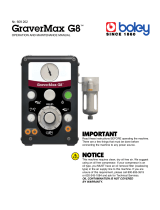
Waxlectric light I + II
Nr. 2150 / 2151
0510 21-6510 A
Ideas for dental technology

4FSJFOOVNNFS)FSTUFMMEBUVNVOE(FS¤UF7FSTJPOCFGJOEFOTJDIBVGEFN(FS¤UF5ZQFOTDIJME
4FSJBMOVNCFSBOEEBUFPGNBOVGBDUVSJOHBSFTIPXOPOUIFUZQFQMBUFPGUIFVOJU
-FOVN©SPEFT©SJFFUMBEBUFEFGBCSJDBUJPOTFUSPVWFOUTVSMBQMBRVFTJHOBM©UJRVFEFM࣌BQQBSFJM
*MOVNFSPEJTFSJFFMBEBUBDPTUSV[JPOFTJUSPWBOPTVMMBUBSHIFUUBEFMM࣌BQQBSFDDIJP
&MOºNFSPEFTFSJFZMBGFDIBEFGBCSJDBDJ³OFTU¡OJOEJDBEPTFOMBQMBDBJEFOUJGJDBEPSBEFMBQBSBUP
̳͔͖͖͎͎͎͎͍͉͔͔͈͓͎͙͍͓͓͚͎͖͓͓͔͒͋͗͋͊͆͆͑͋ͥ͐͆͆͆͒͋͘͘͡͏͇͎͕͖͎͇͔͖͆͑͐͋͆͘͝
ᄴᅧᄟᅨ历㈓Ⴅ朙渼䐁აᄎჹ曡嶊ჴᅍᅵᄵᅤᅰჵ曡嶊ჴ㖧历㈓ᅦᅖᅨჱ栴津მᄒწᄄჟႦ
饝逭鰽螙錅麝黱鷽鸑銐蒱蒱錅麅鷁蒱蒱鷙鄆ꦑ鱑ꫝ饝誙鰵鸉餶襉襥

1 2
43
5 6
7 8

9 10
11 12
13 14
15 16

1817
2019
2221
23 24

1. Introduction
We are pleased with your decision to purchase
the Waxlectric light I or
Waxlectric light II. This device sets a new stan-
dard with regard to functionality,
performance and safety.
Please read the following operating
instructions carefully and observe the
information they contain in order to
ensure a long and trouble-free service
life.
• An external transformer supplies the wax
knife with 12 V power. As a user, this
increases your safety during your daily work
with the Waxlectric light.
• The defining feature of the Waxlectric light is
its heater which is located directly in the mod-
elling tips. This allows the tips to react more
rapidly to temperature changes. The knife’s
thermal dynamics are markedly improved by
the highly heat conductive special alloy.
• The electric wax knife is extremely service
friendly. The modelling tip surfaces are not
finished and can therefore be easily reground
as required. Should the heater develop a
fault, only the tip need be replaced.
The wax knife no. 2155-0112, Large
Wax Knife (refer to “Accessories”)
may NOT be reground or
re-sharpened.
2. Application Area
The Waxlectric light is an electronically
controlled wax knife, suitable for practically all
modelling and waxing-up applications.
It is available in either a one- or a two-channel
version.
The operating temperature can be infinitely
adjusted in 1°-increments from 50°C to 200°C
[122°F to 392°F]. However, do not set the
temperature too high, as some waxes are very
sensitive to overheating.
2.1 Ambient Conditions
in Accordance with DIN EN 61010
The unit may only be operated:
• Indoors;
• Up to an altitude of 2,000 m above sea level;
• At an ambient temperature range between 5 -
40ºC [41 - 104ºF]
• At a maximum relative humidity of 80% at
31ºC [87.8ºF], dropping in a linear manner to
50% relative humidity at 40ºC [104ºF]*);
• With mains power where the voltage fluc-
tuations do not exceed 10% of the nominal
value;
• Under over-voltage category II conditions;
• Under contamination level 2 conditions.
*) Between 5 – 30°C [41 – 86°F], the unit can be operated at
a relative humidity of up to 80%. At temperatures between
31 – 40°C [87.8 – 104°F], the humidity must decrease
proportionally in order to ensure operational readiness (e.g.,
at 35°C [95°F] = 65% humidity; at 40°C [104°F] = 50% hu-
midity). The unit may not be operated at temperatures above
40°C [104°F].
3. Hazard Information
3.1 Symbology
Danger
This indicates a direct risk of injury.
Electrical current
This indicates a hazard due to
electrical current.
Attention
Hot surfaces.
Attention
Failure to observe the associated
information can result in damage to
the unit.
Note
This provides the operator with useful
information to make working with the
unit easier.
Only intended for indoor use.
Waxlectric light I + II
No. 2150 / 2151
ENGLISH
- 13 - EN

Observe the operating instructions.
3.2 Hazard Information
• The modelling tips can reach a
maximum operating temperature of 200°C
[392°F].
• While working the tip of the heating
handle becomes very hot.
• Incorrect handling presents the risk of
burns!
• When setting up and operating please pay
attention that the cables do not encounter
hot parts.
• NEVER place the handpiece on a flam-
mable surface or cover it! Fire hazard!
• Do not put any combustible or
flammable objects close to the unit.
• The wax knife is solely intended for work-
ing modelling waxes.
• NEVER hold the wax knife directly in an
open flame (e.g., a Bunsen burner)!
• Processing other materials may result in
hazards to the user!
• Only operate the equipment under super-
vision
• Only intended for indoor use. The unit is
only designed for dry applications and
may not be operated or stored outdoors
or under wet conditions.
• Units exhibiting damaged connecting
lines or other defects must be taken out of
service immediately.
• Do not cover the transformer during op-
eration.
• Protect the transformer against water and
moisture.
• Unroll the transformer’s connecting cord
during operation (a rolled cord represents
an overheating hazard in case of short
circuits).
• Use only the OEM mains power supply
unit!
3.3 Liability Exclusion
Renfert GmbH shall be absolved from all claims
for damages or warranty if:
• The product is employed for any purpos-
es other than those cited in the operating
instructions;
• The product is altered in any way other
than those alterations described in the
operating instructions;
• The product is repaired by other than an
authorized facility or if any but Renfert
OEM parts are employed;
• The product continues to be employed,
despite obvious safety faults or
damage;
• The product is subjected to mechanical
impacts or is dropped.
4. Installation / Startup
• If you have also ordered the quiver and tip
holder you must mount them on the control
unit:
- Quiver:
Position the quiver on the side
(Figure 1), then first move it up
(Figure 2) and then towards the front (Fig-
ure 3) to lock it in place.
- Tip holder:
Hook the retainer tabs of the tip holder into
the openings on the back of the control unit
(Figure 4), then tilt the holder down until it
locks in place (Figure 5).
• Screw the desired modelling tip into the
handpiece (Figure 6). Make sure the tip
IS NOT skewed or cross-threaded!
• Connect the handpieces to the control unit
(Figure 7). The connecting sockets are loca-
ted on the underside of the control unit.
On the 2-channel-models, make sure the
handpieces are connected to the correct
sockets. The handpieces are marked with
coloured rings (red / yellow). The ring colours
can also be found on the control unit’s opera-
ting side (Figure 8).
The pins must audibly snap into the
sockets.
- 14 -EN

5.4 Storing the Modelling Tips and
Handpieces
You can safely leave unused modelling tips in
the tip holder for storage (Figure 13).
During breaks, you can safely leave unused
handpieces in the quiver (Figure 14).
NEVER insert the handpieces into the
tip holder (Figure 15). This can dam-
age both the tip holder as well as the
control unit.
NEVER place the handpiece on a flam-
mable surface or cover it! Fire hazard!
Tip holders and quiver are available as sepa-
rate accessories (refer to “Accessories”).
Tips and Notes
• In order to reduce the risk of break-
ing the probes, dip them into the
hard wax block with the rounded
back section! The wax will melt more
quickly and this allows to pick up a
greater amount of wax (Figure 24).
• More rapid and efficient modellation
(time savings of up to 30%!) can be
achieved by pre-warming the wax in
a Renfert Vario E. Wax can be pro-
cessed more gently and cools more
rapidly. This reduces shrinkage to a
minimum.
• Because the tip insert surfaces are
not finished, they can – starting from
their basic shape – be ground, bent,
or polished to suit your particular
requirements.
• The handpiece cables can be guided
through an appropriate retainer (eye,
hook, etc.) to allow the handpieces
to hang down from above the work
area at the ideal height. This “cable
/ handpiece overhead suspension”
permits significantly faster handpiece
access / changeovers.
• By setting the temperature at ap-
prox. 50°C [122°F], you can use the
slightly warmed Waxlectric blade to
“shave” the wax crown edge onto the
die while the wax is warm.
• Feed the handpiece connecting cables
through the guide rings towards the front of
the unit (Figure 9).
• Connect the mains power supply unit to the
control unit. The connecting socket is located
on the underside of the control unit (Figure
10a). Feed the power cord out through the
opening on the back of the unit (Figure 10b).
• Using the power cord provided, connect the
transformer to the mains power supply (Fig-
ure 11).
Use only the OEM mains power supply
unit!
5. Operation
5.1 Operating Elements
(Figure 12)
A ON /OFF switch
B LED indicator
C Temperature adjustment, left channel
D Temperature adjustment, right channel
(Waxlectric light II only).
5.2 Switching the Unit ON / OFF
The unit is switched on and off at switch (A).
The LED (B) goes on once the unit is
switched on.
5.3 Temperature Adjustment
The modelling tip temperature is adjusted with
the aid of knobs C and D (Figure 12).
After a temperature adjustment, the modelling
tip requires several seconds to reach the new
temperature setting.
NEVER attempt to heat the tips more
rapidly by holding them in an open
flame. This will destroy the tips.
The employed heating elements have been
specially tailored to the individual modelling tips.
However, manufacturing tolerances
may result in minor differences
between the set temperature and the
actual temperature at the
modelling tip.
- 15 - EN

6. Cleaning / Maintenance
Never rinse the unit off with water!
Do not use steam to clean the unit!
Hot steam penetrating the unit can
damage it.
Use a soft, lint-free cloth to wipe the unit down
from time-to-time.
Never use cleansers containing
solvents!
Wipe the tips off after use; This will prevent wax
from burning onto the tip and maintain the tip’s
optimal heat conducting properties.
6.1 Changing Tips
Burn hazard!
The modelling tips may be hot. Always
allow the tips to cool before changing
them.
• Unscrew the tip (Figure 16).
• Make sure the O-ring is properly seated
(Figure 17).
• Insert the new tip, making sure it is straight,
and hand-tighten it. Make sure the tip IS NOT
skewed or cross-threaded (Figure 18).
Make sure the O-ring is properly
seated (Figure 17), the O-ring
provides a seal against the wax.
Modelling tips which are not being used can
be safely and handily stored in the tip holder
(Figure 13).
6.2 Cork Replacement
• Unscrew the tip (Figure 16).
• Pull the cork sleeve off towards the front
(Figure 19).
• Install a new cork sleeve, making sure it is
straight (Figure 20).
• Screw the tip back on (Figure 18).
6.3 Cleaning the Quiver and Tip
Holder
The tip holder and quiver can be easily re-
moved for cleaning.
• Tip holder:
Press gently from the side (Figure 21), then
flip upwards and pull off towards the rear
(Figure 22).
• Quiver:
Rotate the quiver downwards and towards
the rear to remove it (Figure 23).
Refer to Chapter 4 for the tip holder and quiver
installation instructions.
7. Spare Parts
Refer to the spares list at the end of this manual
for numbers of wearing and replacement parts.
8. Disposal instructions for
countries in the EU
To conserve and protect the environment,
prevent environmental pollution and improve
the recycling of raw materials, the European
Commission adopted a directive that requires
the manufacturer to accept the return of elec-
trical and electronic units for proper disposal or
recycling.
Within the European Union units with this
symbol should not therefore be disposed of in
unsorted domestic waste:
For more information regarding proper disposal
please apply at your local authorities.
9. Warranty
Provided the unit is properly used and with the
exception of components subject to normal
wear, Renfert warrants the all components of
the Waxlectric light for a period of 3 years.
Warranty claims may only be made upon
presentation of the original sales receipt from
the authorized dealer. Components subject to
natural wear (e.g., all tips, cork sleeves, etc.)
are excluded from this
- 16 -EN

warranty. The warranty is voided in case of
improper use; failure to observe the operating,
cleaning, maintenance, and connection instruc-
tions; in case of independent repairs or repairs
by unauthorized personnel; if spare parts from
other manufacturers are employed, or in case
of unusual influences or influences not in com-
pliance with the utilization instructions.
Warranty service shall not extend the
original warranty.
10. Technical
Specifications
Max. power consumption:
5 W (Waxlectric light I)
10 W (Waxlectric light II)
Min. operating temperature: 50°C [122°F]
Max. operating temperature: 200°C [392°F]
Supply voltage: 12 VDC
Transformer:
Input voltage: 100-240 VAC, 50/60 Hz
Output voltage: 12 VDC / 1A
11. Standard Delivery
1 Control unit
1 Handpiece (or 2 handpieces with the Wax-
lectric light II)
1 Modelling insert, No. 2155-0102
(for Waxlectric light I),
or 2 inserts, No. 2155-0101 + 2155-0103
(for Waxlectric light II)
1 Transformer
1 Operating instruction, with spare parts list
12. Delivery Versions
No. 2150-0000 Waxlectric light I, 230 V
No. 2150-1000 Waxlectric light I, 120 V
No. 2151-0000 Waxlectric light II, 230 V
No. 2151-1000 Waxlectric light II, 120 V
13. Accessories
No. 2151-1500 Kit of holders Waxlectric
No. 2155-0101 1 probe, small
No. 2155-0102 1 probe, medium
No. 2155-0103 1 probe, large
No. 2155-0104 1 blade, narrow
No. 2155-0105 1 blade, wide
No. 2155-0106 1 blade, chamfer
No. 2155-0107 1 Hollenback, horizontal
No. 2155-0108 1 Hollenback, vertical
No. 2155-0109 1 probe, mini, angled
No. 2155-0110 1 lance blade
No. 2155-0111 1 blade, beaver-tail
No. 2155-0112 1 large wax knife
2155
-0101 -0102 -0103 -0104 -0105 -0106 -0107 -0108 -0109 -0110 -0111 -0112
- 17 - EN

We reserve the right to make technical changes.
14. Troubleshooting
Error Possible cause Corrective action
LED B (Figure 12)
fails to go on.
• Control unit not
switched on.
• Power supply
interrupted.
• Plug not fully inserted
in the control unit.
• Faulty control unit.
• Faulty transformer.
• Short circuit in the tip.
• Switch the control unit on at switch “A”.
• Check the power supply and reconnect, as
required.
• Push the plug in until it unmistakably locks
in place.
• Have unit replaced by Service Department.
• Replace with spare (refer to the spare parts
list).
• Clean the tip and handpiece
(use compressed air).
• Replace the tip.
• Faulty heater handle
--> Replace with spare
(refer to the spare parts list).
Unit operating, but
no temperature at
the tip.
• Tip not properly
screwed in.
• Tip / handpiece contact
contaminated.
• Faulty tip.
• Handpiece cable not
properly plugged into
the control unit.
• Plug on handpiece
cable shows signs of
corrosion.
• Hand tighten tip.
• Clean the contact
(use compressed air).
• Replace the O-ring
(refer to the spare parts list).
• Replace with a new tip
(refer to Sec. 13 / “Accessories”).
• Fully insert the handpiece cable into the
socket until the cable locks in place.
• Reinsert the plug, clean the contacts, if
required.
The tip fails to
reach the desired
temperature.
• Incorrect power supply
to the tip because the
OEM mains power
supply unit is not being
used.
• Use the OEM mains power supply unit.
- 18 -EN
/