Page is loading ...

Important: Read this manual before installation or use of this
product. Failure to do so can result in serious personal injury or
damage to the product. RETAIN THIS MANUAL!!
Notice to all installers and users
The following instruction manual is provided as a guide to installers and
users. The situations and conditions described in this manual cannot
represent all situations that may be encountered during the installation or
dismantling process. The use of common sense, good judgment, and safe
practices must be followed to prevent injury and damage to the product.
Equipment/manpower for installation
*Ground cloth, sledge hammer or breaker hammer fitted with stake driver
bit and stake puller.
*A minimum of (3) adults are required for installation
20’ x 50’ Titan Series pole tent single piece top
instruction and owner’s manual
Note: 20 x 40 shown
20 x 40 shown
Tent occupancy guidelines
*Sit down (round tables) = 100 persons
*Cathedral (row) seating = 160 persons
*Stand up / cocktail = 200 persons

Personal safety
Personal safety must be practiced during the installation process to avoid
injury to yourself and others. The following practices must be adhered to
during installation and dismantling.
*Stay alert: Be aware of surroundings at all times; never use drugs,
alcohol or other foreign substances during installation or dismantling.
*Wear the proper safety attire: hard hat, gloves, steel toed shoes,
safety glasses, and hearing protection are required.
*Dress appropriately: remove jewelry; do not wear loose clothing;
keep long hair away from power equipment and other dangerous areas.
*Use proper lifting procedures: use legs for lifting, do not lift heavy
items alone
*Maintain balance: do not over reach, maintain footing at all times
Personal safety
Product specifications
Hardware (what’s included)
Weather conditions
Installation site
20’ wide (1) pc top pole tent anchoring and staking
Installation procedure
Tent dismantling
Maintenance and Care
Warranty Information
Contents of this manual

20’ x 50’ Titan Series pole tent specification sheet
Feature Specification Note
Style / Series Traditional / Titan Series Pole supported tension tent
Width 20 ft / 6.1 m
Length 50 ft / 15.2 m
Total height 14 ft / 4.27 m If using standard 7 ft side poles
Eave height 7 ft / 2.13 m See diagram
Pitch 7 ft / 2.13m See diagram
Area 1000 sq ft / 93 sq meters
Expandable No Tent top is 1 piece
Side pole spacing 10 ft / 3 m
Number of side poles / legs 14 Single piece poles
Side pole diameter / (thickness) Aluminum = 2 3/8” / (5/32” =
0.156”)
Galvanized steel = 2 3/8” / (1/16” =
0.062”)
Side pole material Round anodized aluminum Galvanized steel available
Number of center poles 4 Center poles are sectional
Center pole material Galvanized structural steel Galvanize regardless of side poles
Fabric weight 16 ounces/yd2 / 540 gsm gsm = grams per square meter
Fabric type PVC coated polyester Blockout (non translucent)
Sidewall rope installed yes Can be replaced
Flame & UV resistant yes Meets NFPA 701 flame retardant
requirements
Mold & mildew resistant yes
Water repellent / resistant yes Seams are heat sealed
Longest component 7’10” (2.4m) or 8’10” (2.7m) Depends on side pole length
Total weight with aluminum side
poles
592 lbs / 268 kgs Weight is with 7’ side poles (weight
slightly higher with 8’ poles)
Total weight with galvanized steel
side poles
620 lbs / 281 kgs Weight is with 7’ side poles (weight
slightly higher with 8’ poles)
• 8’ long side poles available
• All center poles are galvanized steel
regardless of side pole selection
material
• Weights do not include side walls
Pitch
Eave
height
Total
height
Side pole
spacing
Diagram is representation only and is not to scale

Diagram represents view from top of tent
20’ x 50’ Titan Series pole tent hardware package (what’s included)
Sidewalls not included and
must be purchased separately
Symbol
Item Size/length Quantity
Diagram/description
Side and corner
poles (bottom is
capped)
7’ or 8’ long (not
including 10” pin
length)
14 Poles may be aluminum or galvanized depending
on customer order
Sectional center
pole (top pole
has open
bottom)
14’ or 15’ (not
including 10” pin
height or 6”
swage
4 Galvanized structural steel (round)
O
Stakes 40”double
headed stake
18
Ratchet / strap
assembly
2” ratchet & 5’
strap with loop
& 8’ strap with
loop
18
NA Wire lock pin NA 4 (8 with 8’
side poles)
For securing the sectional center pole(s)
NA Tent top (single
piece)
20’ x 50’ 1
NA Tent top storage
bag
NA 1
10” pin
10” pin
6” swage
Ratchet buckle
Side poles have welded cap on bottom
1’ extension included with 8’ side poles

Weather conditions
Weather conditions cannot be predicted and can change rapidly. The installer must use good
judgment, common sense and have knowledge of the current and future weather conditions.
Be aware of the following weather conditions:
*Rain – Rain can cause water to collect in areas on the tent top. This added weight can
cause damage to the fabric. Ground moisture can also cause the frame to sink in addition to
the stakes loosing holding force.
*Wind – Do not install the tent in heavy wind conditions as it may cause damage to the top
and frame. Wind can also cause an existing installed tent to loose tension in all areas.
*Lighting – Do not install a tent in conditions where lightning can occur; All tent installers
and occupants must evacuate until lightning has ceased.
*Snow/hail/ice – Tents and shelters are not designed as permanent structures and cannot
withstand the weight of snow/hail/ice loading. These products must NOT be installed in these
conditions.
Installation site
The installation site is of the utmost importance. The installer must be aware of local building
codes and fire regulations. The installer must also examine the installation site for the proper
anchoring methods. The following must be verified to assure proper installation and prevent
damage to the product.
*Underground utilities – Always contact local utility companies prior to installation. Gas,
electrical, cable, sewer, water, oil, and septic line presence must be verified.
*Overhead utilities/obstructions – Always confirm if overhead utilities or obstructions can
cause personal injury or damage to the product during installation.
*Soil conditions – The soil conditions must be adequate to allow for secure anchoring
*General site condition – the site must be relatively flat, elevated and free of clutter and
debris.
*Area / space – the site must have sufficient space to allow for anchoring
*Accessibility – the site must be accessible for event deliveries such as trucks, vehicles as
applicable
*Evacuation / exit – the site must have adequate evacuation routes in the event of
emergency
Installer responsibilities prior to staking and anchoring:
*Assure that the canopy, tent, shelter, or structure is properly secured.
*Contact all related underground utility “call before you dig” authorities prior to staking.
*Note: Dremcor LLC assumes no responsibility for the method of installation that the installer
chooses or the failure to contact the proper authorities as noted above. Each state, county,
township or city may have unique temporary structure installation codes and requirements so
it is important that the proper codes & requirements are followed. This manual may not
recommend the correct quantity of stakes based on soil conditions at the installation site. It is
the installer’s responsibility to install additional staking or tiebacks as needed.

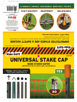
20’ wide pole tent anchoring & staking guide
soil
6”
soil
soil
YES
NO!!
NO!!
Tent top
*Stakes must be vertical with no more than 6”
above soil
*Stakes cannot be more than 10 degrees “off
center angle”
Ratchet
buckle
5’
Tent size
(W x L)
Minimum
stake length
(inches)
Number
of
stakes
Number of
ratchet/ strap
assemblies
20’ x 20’ 36” 12 12
20’ x 30’ 36” 14 14
20’ x 40’ 36” 16 16
20’ x 50’ 36” 18 18
20’ x 60’ 36” 20 20
Diagram represents overhead view
O = stake
= ratchet / strap assembly
soil
*Stakes should be spaced approximately 5’ from legs
Above left diagram represents a 20’ x 20’ pole tent. Same
condition applies to pole tents longer than 20’.
Securing strap to tent top
(see below)
Option #1: Noose loop pulled tight thru plate (good)
Option #2: S hook attached to plate (best); up to (3)
S hooks can be installed to the white plate
Dremcor has both strap options available for purchase
#1
#2
Staking guide
Ratchet/strap attachment guide
Securing strap with ratchet to the stake
(see below)
Option #1: Noose loop around stake
Option #2: Stake inserted to double D ring
Dremcor has both strap options available for purchase.
Double D ring option eliminates noose forming and
chance of strap pulling over top of stake
#1
#2

Installation procedure
Ground cloth and tent top preparation
*Layout a ground cloth or protective tarp in the location where the tent will
be installed. The ground cloth should be larger in area than the tent top to
offer complete protection for the tent top (see diagram below)
*Remove the tent top from the storage bag and unroll onto the ground
cloth. The brass grommets must be facing upward when unrolling the tent
top (see diagram below)
*Pull the tent top tight around the perimeter while keeping a “square”
condition. The tent top will not be flat due to the slope & design of the tent.
DO NOT WALK ON THE TENT TOP AS IT CAN CAUSE DAMAGE.
Ground cloth
Tent top
Brass grommets
facing up
View from top of installation site
Pull tent top tight at
corner locations to
produce a “square
up” condition
Note: The above diagram represents a 20 x 20 pole tent. The
same concept applies to pole tents regardless of size.

Stake and ratchet preparation
*Attach the S hook strap or 8’ loop strap (strap without the ratchet buckle) to the white
aluminum plates at each corner and side location. Note that (2) loop straps will be
installed on each corner. Turn the loop strap inside out and pull the strap thru the loop
to create a noose and pull tight (see anchoring and staking page for additional options
and photos).
*Layout the stakes and ratchet hardware around the perimeter of the tent top. Place
(2) stakes and ratchet/strap assembles at each corner 90 degrees apart.
*Drive the stakes into the ground vertically approximately 5’ from the grommet
locations. The top of the stakes should have no more than 6” exposed above the
ground (refer to anchoring and staking section for additional details).
*Attach the ratchet with loop strap to the stake by turning the loop inside out and
pulling the ratchet thru the loop over the stake head to create a noose and pull tight.
The noose must not come off the head of the stake when pulling tight (see anchoring
and staking page for additional options and photos). Double D rings are available for
purchase for stake attachment (see photo below)
*For each of the ratchet assemblies, insert the loop strap into the reel bar slot of the
ratchet with loop assembly and tighten the ratchet slightly. Note the ratchet handle
should be facing upward.
Installation procedure (continued)
Option #1 (loop
strap)
Option #2 (Double D
ring attachment –
optional purchase)

Pole installation
*Layout the corner and side poles around the perimeter of the tent top in the brass
grommet locations. DO NOT PLACE THE POLES ON THE TENT TOP.
*Insert the corner pole pin thru the white aluminum plate on the underside of the
tent top and thru the brass grommet at each corner location. CARE MUST BE TAKEN
NOT TO DAMAGE THE TENT TOP IN THIS PROCESS. USE ONE HAND TO PLACE ON
TENT TOP AND OTHER HAND TO POSITION THE PIN THRU THE HOLES (SEE DIAGRAM
BELOW)
Installation procedure (continued)
*Tie off the jump ropes attached to the aluminum plates at each corner pole
location. The jump ropes secure the tent top to the poles in the event of wind.
*Assemble the center pole by sliding the pole with 10” pin over the swaged end
bottom center pole (see diagram below). Align the holes and insert the wire lock
pin and latch the wire properly to the pin. THE WIRE LOCK PIN MUST BE
INSTALLED AND SECURED PROPERLY TO PREVENT PERSONAL INJURY AND
PRODUCT DAMAGE. (See wire lock pin correct assembly photo below).
Bottom center pole with 6” long swage
Top center pole with 10” long pin
Important note: The top center pole does not have a weld on bottom cap. The side
and corner poles have the weld-on bottom caps.
1’ long center extension for use with 8’ long side poles
(installs in center of poles noted above)
View from underside of tent top
View from topside of tent top

*Insert the center pole pin thru the top of the center white aluminum plate and the
brass grommet. CARE MUST BE TAKEN IN THIS STEP SO THE PIN DOES NOT DAMAGE
THE TENT TOP.
*Lift the center pole and move the bottom toward the center of the tent while leaving
at an angled position (see diagram below)
*Tie off the center pole jump rope that is attached to the center aluminum plate. The
rope should attach around eye level when standing on the ground.
*Remove the drop cloth and lift the center pole into an upright vertical position.
*Install the side poles and tighten the ratchets until all poles are vertically straight.
This step may require some ratchet and strap adjustments.
*The center pole must be vertically straight at the end of this process.
*Fold the excess ratchet straps into the ratchet buckle
Installation procedure (continued)
Corner
pole
Assembled
center pole
Tent top
Tent top
Tent dismantling
*Loosen the ratchet assemblies and remove the side poles only.
*Lift and angle the center pole slight to reduce tension on top.
*Place ground cloth or tarp under the tent
*Loosen the center pole jump rope and remove the center pole.
*Loosen the corner ratchets and remove the corner poles.
*Disassemble all ratchet assemblies and remove the stakes
*Fold and roll the tent top as tightly as possible to fit into the storage bag. DO NOT
WALK ON THE TENT TOP.
*Place the tent top into the storage. DO NOT STORE THE TENT TOP IN THE BAG WHEN
WET.

Maintenance and care
Dremcor provides high quality products that can last for many years of use. Failure to maintain and care
for the tent top can result in premature wear and degradation. The following procedures are strongly
recommended to maintain your product.
*Never place the tent top on rough surfaces such as gravel, asphalt, tree limbs, rocky soil, and concrete.
These surfaces can cause pinholes. Always use a ground cloth during installation and disassembly.
*Clean your tent top regularly with a soft brush and neutral cleaners
*Never walk on the tent top as this can cause pinholes and damage.
*Never store tent tops when wet. This will promote mold and result in premature degradation of the
fabric.
*Do not use harsh cleaners with contain bleach or solvents.
*Do not use excessively abrasive and intense cleaning methods such as power washers and wire brushes.
Warranty information
Dremcor LLC warrants this product to be free from material and workmanship defects for a period of
(1) year from the date of purchase. Warranty applies to the original purchaser only and is non
transferable. All products are thoroughly inspected during the manufacturing process and prior to
shipment. The following defects/conditions are NOT covered under warranty:
*Damage caused by failure to follow proper installation procedures
*Damage caused by improper anchoring procedures and/or insufficient anchoring
*Damage caused by failing to use ground cloths or tarps
*Damaged caused by Acts of God including (not limited to); tornadoes, hurricanes, floods, excessive
wind, hail, lightning, etc
*Damage caused by insects, rodents, and animals
*Damage/deterioration caused by improper storage
*Pin holes, tears caused by walking on the fabric
*Repairs or modifications to the frame and/or fabric
*Damage caused by falling objects such as tree limbs
*Damage caused by use of harsh chemicals, fireworks, flames, sharp objects
In the event of a defect in material or workmanship, Dremcor LLC will replace or repair the product.
Photos and an explanation of the defect may be requested of the purchaser. Dremcor LLC reserves the
right to refuse warranty if the above exclusions are confirmed.
In the event of a warranty claim, Dremcor LLC will not compensate the purchaser for loss of income,
wages, travel expenses, equipment rental and third party fees. Product purchase constitutes
acceptance of these terms.
/