Page is loading ...

1 - ENG
DWFP12658
ROOFING COIL NAILER
CLOUEUSE POUR TOITURE À CLOUS EN BOBINE
CLAVADORA PARA TECHADO A RESORTE
INSTRUCTION MANUAL
GUIDE D’UTILISATION
MANUAL DE INSTRUCCIONES
If you have questions or comments, contact us.
Pour toute question ou tout commentaire, nous contacter.
Si tiene dudas o comentarios, contáctenos.
1-800-4-
DeWALT
• www.dewalt.com
9R199590RA
INSTRUCTIVO DE OPERACIÓN, CENTROS
DE SERVICIO Y PÓLIZA DE GARANTÍA.
ADVERTENCIA: LÉASE ESTE INSTRUCTIVO
ANTES DE USAR EL PRODUCTO.
INSTRUCTIONS DE FONCTIONNEMENT,
CENTRES DE SERVICE, POLITIQUE DE
GARANTIE. AVERTISSEMENT : LISEZ CES
INSTRUCTIONS AVANT D'UTILISER L'APPAREIL.

2 - ENG
• Actuating tool may result in flying debris, collation
material, or dust which could harm operator’s eyes.
Operator and others in work area MUST wear safety
glasses with side shields. These safety glasses must
conform to ANSI Z87.1 requirements (approved glasses
have “Z87” printed or stamped on them). It is the
employer’s responsibility to enforce the use of eye
protection equipment by the tool operator and other
people in the work area. (Fig. A)
• Alwayswearappropriatepersonalhearingandother
protection during use. Under some conditions and
duration of use, noise from this product may contribute
to hearing loss. (Fig. A)
• Useonlyclean,dry,regulatedair.Condensationfrom
an air compressor can rust and damage the internal
workings of the tool. (Fig. B)
• Regulate air pressure. Use air pressure compatible
with ratings on the nameplate of the tool. [Not to
exceed 120 psi (8.3 bar).] Do not connect the tool to a
compressor rated at over 200 psi. The tool operating
pressure must never exceed 200 psi even in the event of
regulator failure. (Fig. C)
• Only use an air hose that is rated for a maximum
working pressure of at least 150 psi (10.3 bar) or
150% of the maximum system pressure, whichever is
greater. (Fig. D)
• Do not use bottled gases to power this tool. Bottled
compressed gases such as oxygen, carbon dioxide,
nitrogen, hydrogen, propane, acetylene or air are not
70 psi
4.9 bar
Fig. C
Fig.B
Fig. A
Fig. D
IMPORTANT SAFETY INSTRUCTIONS
FOR PNEUMATIC TOOLS
SAVE THESE INSTRUCTIONS
WARNING: When using any pneumatic tool, all safety precautions, as outlined below,
should be followed to avoid the risk of death or serious injury. Read and understand all
instructions before operating the tool.
DEFINITIONS - SAFETY GUIDELINES
The definitions below describe the level of severity for each signal word. Please read the
manual and pay attention to these symbols.
DANGER: Indicates an imminently hazardous situation which, if not avoided, will
result in death or serious injury.
WARNING: Indicates a potentially hazardous situation which, if not avoided, could
result in death or serious injury.
CAUTION: Indicates a potentially haz ard ous situation which, if not avoided, may
result in minor or mod er ate injury.
NOTICE: Used without the safety alert symbol indicates a situation which, if not
avoided, may result in property damage.

3 - ENG
for use with pneumatic tools. Never use combustible
gases or any other reactive gas as a power source for this
tool. Danger of explosion and/or serious personal injury
may result. (Fig. E)
• Usecouplingsthatrelieveallpressurefromthetool
when it is disconnected from the power supply.
Use hose connectors that shut off air supply from
compressor when the tool is disconnected. (Fig. F)
• Disconnect tool from air supply when not in use.
Always disconnect tool from air supply and remove
fasteners from magazine before leaving the area or
passing the tool to another operator. Do not carry
tool to another work area in which changing location
involves the use of scaffoldings, stairs, ladders, and
the like, with air supply connected. Do not make
adjustments, remove magazine, perform maintenance
or clear jammed fasteners while connected to the
air supply. If the contact trip is adjusted when the tool
is connected to the air supply and nails are loaded,
accidental discharge may occur. (Fig. G)
• Connect tool to air supply before loading fasteners
to prevent an unintentional fastener discharge during
connection. The tool driving mechanism may cycle
when the tool is connected to the air supply. Do
not load fasteners with the trigger or the contact trip
depressed to prevent unintentional driving.
• Donotremove,tamperwith,orotherwisecausethe
tool, trigger, or contact trip to become inoperable.
Do not tape or tie trigger or contact trip in the on
position. Do not remove spring from contact trip. Make
daily inspections for free movement of trigger and contact
trip. Uncontrolled discharge could result.
• Inspect tool before use. Do not operate a tool if
any portion of the tool, trigger, or contact trip is
inoperable, disconnected, altered, or not working
properly. Leaking air, damaged parts or missing parts
should be repaired or replaced before use. Refer to
Repairs. (Fig. H)
• Donotalterormodifythetoolinanyway.(Fig. I)
• Alwaysassumethatthetoolcontainsfasteners.
• Donotpointthetoolatco-workersoryourselfatany
time. No horseplay! Work safe! Respect the tool as a
working implement. (Fig. J)
• Keep bystanders, children, and visitors away while
operating a power tool. Distractions can cause you to
lose control. When tool is not in use, it should be locked
in a safe place, out of the reach of children.
• Removefingerfromtriggerwhennotdrivingfasteners.
• Never carry tool with finger on trigger. Accidental
discharge could result. Using the trigger lock-off will
prevent accidental discharge.
Fig. E
Fig. F
Fig. I
Fig. J
Fig. G
Fig. H

4 - ENG
• Donotoverreach.Maintain proper footing and balance
at all times. Loss of balance may cause personal injury.
(Fig. K)
• Make sure hose is free of obstructions or snags.
Entangled or snarled hoses can cause loss of balance
or footing.
• Usethetoolonlyforitsintendeduse. Do not discharge
fasteners into open air, concrete, stone, extremely hard
woods, knots or any material too hard for the fastener
to penetrate. Do not use the body of the tool or top cap
as a hammer. Discharged fasteners may follow unex-
pected path and cause injury. (Fig. L)
• Always keep fingers clear of contact trip to prevent
injury from inadvertent release of nails. (Fig. M)
• Refer to the Maintenance and Repairs sections for
detailed information on the proper maintenance of the
tool.
• Always operate the tool in a clean, lighted area. Be
sure the work surface is clear of any debris and be
careful not to lose footing when working in elevated
environments such as rooftops.
• Do not drive fasteners near edge of material. The
workpiece may split causing the fastener to ricochet,
injuring you or a co-worker. Be aware that the nail may
follow the grain of the wood (shiner), causing it to protrude
unexpectedly from the side of the work material. Drive the
nail perpendicular to the grain to reduce risk of injury. (Fig. N)
• Donotdrive nailsontotheheads ofotherfasteners
or with the tool at too steep an angle. Personal injury
from strong recoil, jammed fasteners, or ricocheted
nails may result. (Fig. O)
• Beawareofmaterialthicknesswhenusingthenailer.
A protruding nail may cause injury.
• Be aware that when the tool is being utilized at
pressures on the high end of its operating range,
nails can be driven completely through thin or very
soft work material. Make sure the pressure in the
compressor is set so that nails are set into the
material and not pushed completely through. (Fig. P)
• Keephandsandbodypartsclearofimmediatework
area. Hold workpiece with clamps when necessary to
keep hands and body out of potential harm. Be sure
the workpiece is properly secured before pressing the
nailer against the material. The contact trip may cause the
work material to shift unexpectedly. (Fig. Q)
• Do not use tool in the presence of flammable dust,
gases or fumes. The tool may produce a spark that
could ignite gases causing a fire. Driving a nail into
another nail may also cause a spark. (Fig. R)
• Keepfaceandbodypartsawayfrombackofthetool
Fig. K
Fig. L
Fig. M
Fig. N
Fig. O

5 - ENG
cap when working in restricted areas. Sudden recoil
can result in impact to the body, especially when
nailing into hard or dense material. (Fig. S)
• Grip tool firmly to maintain control while allowing
tool to recoil away from work surface as fastener is
driven. In bump action mode (contact actuation mode)
If contact trip is allowed to recontact work surface
before trigger is released an unwanted fastener will
be driven.
• Choiceoftriggeringmethodisimportant.Checkthe
manual for triggering options.
BUMP OR CONTACT ACTUATION TRIGGER MODE
• When using the bump action trigger mode, be
careful of unin tentional double fires resulting from
tool recoil. Unwanted fasteners may be driven if the
contact trip is allowed to accidentally re-contact
the work surface. (Fig. T)
TOAVOIDDOUBLEFIRES:
• Do not engage the tool against the work surface
with a strong force.
• Allowthetooltorecoilfullyaftereachactuation.
• Usesequentialactiontriggermode.
• Whenbumpactuatingthenailer,alwayskeeptoolin
control.
Inaccurate placement of tool can result in
misdirected discharge of a fastener.
SEQUENTIAL ACTION TRIGGER MODE
• Whenusingthesequentialactiontriggermode,do
not actuate the tool unless the tool is placed firmly
against the workpiece.
• DEPTH ADJUSTMENT: To reduce risk of serious injury
from accidental actuation when attempting to adjust
depth, ALWAYS:
• Disconnectairsupply.
• Engagetriggerlock
• Avoidcontactwithtriggerduringadjustments.
• Do not drive nails blindly into walls, floors or other
work areas. Fasteners driven into live electrical wires,
plumbing, or other types of obstructions can result in
injury. (Fig. U)
• Stayalert,watchwhatyouaredoingandusecommon
sense when operating a power tool. Do not use tool
while tired or under the influence of drugs or alcohol.
A moment of inattention while operating power tools may
result in serious personal injury.
WARNING: Some dust created by power sanding, sawing,
grinding, drilling, and other construction activities contains
chemicals known to the Sate of Califomia to cause cancer,
birth defects or other reproductive harm. Some examples of
these chemicals are:
Fig. Q
Fig. R
Fig. S
Fig. P
Fig. T
FIG. U

6 - ENG
• Lead from lead-based paints
• Crystallinesilicafrombricksandcementandothermasonryproducts
• Arsenic and chromium from chemically-treated lumber.
Your risk from these exposures varies, depending on how often you do this type of
work. To reduce your exposure to these chemicals: work in a well ventilated area, and
work with approved safety equipment, such as those dust masks that are specially
designed to filter out microscopic particles.
WARNING: Use of this tool can generate and/or disburse dust, which may cause
serious and permanent respiratory or other injury. Always use NIOSH/OSHA approved
respiratory protection appropriate for the dust exposure. Direct particles away from
face and body. Always operate tool in well-ventilated area and provide for proper dust
removal. Use dust collection system wherever possible.
WARNING: ALWAYS USE SAFETY GLASSES. Everyday eyeglasses are NOT safety
glasses. Also use face or dust mask if operation is dusty. ALWAYS WEAR CERTIFIED
SAFETY EQUIPMENT:
• ANSIZ87.1eyeprotection(CAN/CSAZ94.3),
• ANSIS12.6(S3.19)hearingprotection,
• NIOSH/OSHArespiratoryprotection.
Before operating this tool, carefully read and understand all instructions in
Important Safety Instructions.
NAIL SPECIFICATIONS
DWFP12658
Nails 0.120" (3 mm) diameter, 15º wire collated roofing nails
Lengths 3/4" (19 mm) - 1-3/4" (44.5 mm)
Air Inlet 1/4" NPT (6.4 mm)
NOTE: Use only D
e
WALT approved fasteners
TOOL PARTS
Fig. 1
A. Exhaust deflector
B. Selectable trigger
C. Air Inlet with quick
connect coupler
D. Canister
E. Door latch
F. Contact tip
G. Depth adjustment wheel
H. Door
I. Tool-Free Shingle Guide
J. Trigger lock button
k. Mode selector button
A
F
J
K
G
C
B
D
I
E
H

7 - ENG
ASSEMBLY
WARNING: Disconnect air line from tool, engage trigger lock and remove
fasteners from magazine before making adjustments or personal injury may
result.
TRIGGER
WARNING: Keep fingers AWAY from the trigger when not driving fasteners to avoid
accidental actuation. Never carry a tool with finger on the trigger. In bump action mode
(contact actuation mode), the tool will drive a fastener if the contact trip is bumped
while the trigger is depressed.
The DWFP12658 is equipped with a selectable trigger. This trigger allows the
operator to select either single sequential action trigger mode or bump action trigger
mode. In accordance with the ANSI Standard SNT-101-2002, the trigger is assembled
in the single sequential action trigger mode. To change the trigger mode, see Actuating
Tool instructions in the Operation section of the manual. The selectable trigger also has
a trigger lock button to keep the trigger locked at all times when the tool is not in use.
AIR FITTING
The tool is equipped with a 1/4" (6.4 mm) male quick connector coupling. A 3/8"
(9.5 mm) male quick connector coupling is available from D
e
WALT and may be used
when a 1/4" (6.4 mm) supply line is not available.
NOTE: A 3/8" (9.5 mm) supply line (and fittings) are required for maximum tool
performance.
WARNING: Always use couplings that relieve all pressure from the tool when it is
disconnected from the power supply. Always use hose connectors that shut off air
supply from compressor when the tool is disconnected.
To install an air fitting
1. Wrap the male end of the fitting with thread seal tape prior to assembly to eliminate
air leaks.
2. To install a 1/4" (6.4 mm) fitting: screw it directly into the air inlet and tighten firmly.
NOTE: If an adapter is in the air inlet, remove it prior to inserting the fitting.
3. To install a 3/8" (9.5 mm) fitting: screw the fitting into the 3/8" (9.5 mm) adapter and
then into the air inlet of the tool and tighten firmly.
OPERATION
PREPARING THE TOOL
WARNING: Read the section titled Important Safety Instructions for Pneumatic
Tools at the beginning of this manual. Always wear eye and ear protection when
operating this tool. Keep the nailer pointed away from yourself and others. For safe
operation, complete the following procedures and checks before each use of the nailer.
NOTICE: To reduce the risk of damage to the tool, only use D
e
WALT pneumatic tool
oil or a non-detergent SAE 20 weight oil. Oil with additives or detergent will damage
tool parts.
1. Before you use the nailer, be sure that the compressor tanks have been properly
drained.
2. Lubricate tool:

8 - ENG
a. Use D
e
WALT pneumatic tool oil or a non-detergent S.A.E. 20 weight oil.
DO NOT use detergent oil or additives as they will damage O-rings and rubber
parts.
b. Use a filter when possible.
c. Add 5 to 7 drops of oil in the air fitting a least twice a day.
3. Wear eye and ear protection.
4. Ensure canister is empty of all fasteners.
5. Check for smooth and proper operation of contact trip. Do not use tool if assembly
is not functioning properly. NEVER tamper with the contact trip. NEVER use a tool
that has the contact trip restrained in the actuated position.
6. Adjust air supply: Ensure air pressure does not exceed recommended operating
limits; 70 to 120 psi, (4.9 to 8.3 bar, 5 to 8.5 kg/cm
2
).
7. Keep tool pointed away from yourself and others.
8. Connect air hose.
9. Check for audible leaks around valves and gaskets. Never use a tool that leaks or
has damaged parts.
WARNING: To reduce the risk of personal injury, disconnect tool from air supply
and engage trigger lock before performing maintenance, clearing a jammed
fastener, leaving work area, moving tool to another location or handing the tool to
another person.
LOADING THE TOOL (FIG. 1–6)
WARNING: Keep the tool pointed away from yourself and others. Serious personal
injury may result.
WARNING: Never load nails with the contact trip or trigger activated. Personal injury
may result.
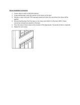
1. Read all Safety Warnings before
using tool.
2. Connect the air supply to the tool.
3. Lift the canister door latch (e) to open
the nail guide door (H).
4. Rotate the canister door (I) open.
5. Adjust the nail platform (J) to properly
accommodate the nail length being
used. Pull the nail platform (J) up or
down for desired nail.
Platform Position Nail Length
lowest position 1-1/2" (38 mm) - 1 3/4" (44.5mm)
center position 1-1/4" (32 mm)
upper position 3/4" (19 mm) - 1" (25 mm)
NOTE: 3/4" (19 mm) nails are not available for this tool.
6. Place the coil on the nail platform (J). NOTE: Observe fastener icon (K) Fig. 4. Insert
fasteners (L) with points down. IMPORTANT: Fasteners must point in the same
direction as they will be driven.
7. Uncoil enough nails [approximately 3" (76 mm)] to reach the nose of the tool.
8. Insert the first nail into the nose and the second nail (M) between the two rails of
the feed pawl as shown in Fig. 5.
Fig. 2
E
H
I

9 - ENG
NOTE: Be careful not to deform the coil of nails during the loading process. Otherwise,
the nail guide door will not close and the nails might not feed consistently.
9. Close the canister door (I) completely.
10. Close the nail guide door (H) making sure the door latch (e) is completely engaged
as shown in Fig. 6.
ACTUATING TOOL
WARNING: To reduce the risk of injury, ALWAYS wear proper eye ANSI Z87.1 (CAN/
CSA Z94.3) and hearing protection ANSI S12.6 (S3.19) when operating this tool. The
tool can be actuated using one of two modes: single sequential actuation trigger mode
and contact actuation trigger mode.
SingleSequentialactuationtriggermode- (Fig. 7)
WARNING: Allow the tool to recoil off the work
surface after actuation. If the contact trip remains
depressed a nail will be driven each time the trigger is
released and pulled, which could result in accidental
actuation, possibly causing injury.
The sequential actuation trigger’s intended use is
for intermittent fastening where accurate fastener
placement is desired.
TooperatethetoolinSinglesequentialactuation
mode:
1. Depress the contact trip firmly against the work
surface.
2. Pull the trigger.
3. Allow the tool to recoil from the work surface.
Fig. 4
K
L
Fig. 3
J
Fig. 5
M
Fig. 6
E
H
Fig. 7
S
Trigger lock button
Trigger mode selector button

10 - ENG
Contact actuation trigger mode - (Fig. 8)
The contact actuation trigger is intended for rapid
fastening on flat, stationary surfaces.
Using the contact actuation trigger mode, two
methods are available: place actuation and contact
actuation.
To operate the tool using the PLACE ACTUATION
method:
1. Depress the contact trip against the work surface.
2. Pull the trigger to drive the fastener.
3. Allow the tool to recoil off the work surface
To operate the tool using the CONTACT
ACTUATION method:
1. Pull the trigger.
2. Depress the contact trip against the work surface. As long as the trigger is pulled,
the tool will drive a fastener every time the contact trip is depressed. This allows
the user to rapidly drive multiple fastener in sequence.
Changing the Actuation Mode -
WARNING: To reduce risk of serious injury, disconnect tool from air supply before
changing actuation mode.
1. Push the (black) trigger lock button down
2. Rotate the (black) selectable trigger button counterclockwise
3. Align the triangular indicator to the desired mode
• ForSequentialMode
• ForContactMode
4. Then push the trigger lock button back up to the un-locked position.
ADJUSTING DEPTH (FIG. 9)
WARNING: To reduce risk of serious injury from
accidental actuation when attempting to adjust depth,
ALWAYS:
• Disconnect air supply and engage trigger
lock.
• Avoidcontactwithtriggerduringadjustments.
The depth that the fastener is driven can be adjusted
using the depth adjustment next to the trigger of
the tool. The depth of drive is factory adjusted to
a nominal setting. Test fire a fastener and check
depth. If a change is desired:
1. To drive the nail shallower, rotate the depth setting wheel (G) to the right.
2. To drive a nail deeper, rotate the depth setting wheel (G) to the left.
The adjustment knob has detents every 1/4 turn. Test drive another fastener and check
depth. Repeat as necessary to achieve desired results. The amount of air pressure
required will vary depending on the size of the fastener and the material being
fastened. Experiment with the air pressure setting to determine the lowest setting that
will consistently perform the job at hand. Air pressure in excess of that required can
cause premature wear and/or damage to the tool.
Fig. 9
G
Fig. 8
C
Trigger lock button
Trigger mode selector button

11 - ENG
SHINGLE GUIDE (FIG. 11, 12)
Adjust shingle guide (O):
1. Loosen the adjusting lever (P) and slide the locking plate to desired position.
2. Tighten adjusting lever firmly.
The locking plate (O) can be used as an aid to position the shingle being nailed a
specific distance (Q) from the front edge of the previous row of shingles (R) as shown.
CLEARING A JAMMED NAIL (FIG. 1, 13)
WARNING: Disconnect air line from tool, engage trigger lock and remove
fasteners from magazine before making adjustments or personal injury may
result.
If a nail becomes jammed in the nosepiece, keep
the tool pointed away from you and follow these
instructions to clear:
1. Disconnect the air supply from the tool.
2. Lift the canister door latch (e) to open the nail
guide door (H).
3. Open the canister door.
4. Remove the jammed nail.
5. Correct any deformation that may have occurred
to the nail coil.
NOTE: Should nails continue to jam frequently in nosepiece, have tool serviced by an
authorized D
e
WALT service center.
COLD WEATHER OPERATION
When operating tools at temperatures below freezing:
1. Make sure compressor tanks have been properly drained prior to use.
2. Keep tool as warm as possible prior to use.
3. Make certain all fasteners have been removed from canister.
4. Put 5 to 7 drops of D
e
WALT pneumatic tool oil in the air inlet.
5. Lower air pressure to 80 psi (5.5 bar) or less.
6. Reconnect air and load nails into canister.
7. Actuate the tool 5 or 6 times into scrap lumber to lubricate O-rings.
8. Turn pressure up to operating level (not to exceed 120 psi) and use tool as normal.
9. Re-lubricate at least once daily.
10. Always drain the compressor tanks at least once a day.
Fig. 11
O
P
Fig. 13
Fig. 12
R
O
Q

12 - ENG
HOT WEATHER OPERATION
Tool should operate normally. However, keep tool out of direct sunlight as excessive
heat can deteriorate bumpers, O-rings and other rubber parts resulting in increased
maintenance.
MAINTENANCE
WARNING: Disconnect air line from tool, engage trigger lock and remove
fasteners from magazine before making adjustments or personal injury may
result.
DAILY MAINTENANCE CHART
ACTION WHY HOW
Lubricate tool with
5-7 drops of D
e
WALT
Pneumatic Tool Oil
Prevents failure
of o-rings
Insert drops into air fitting
on end cap of tool
Drain compressor tanks
and hoses daily
Prevents accumulation
of moisture in
compressor and nailer
Open petcocks or other
drain valves on compressor
tanks. Allow any accumulated
water to drain from hoses
Clean canister, feed
piston area and contact
trip mechanism.
Permits smooth
operation of magazine,
reduces wear and
prevents jams.
Blow clean with compressor
air. The use of oils, lubricants
periodically or solvents is
not recommended as they
tend to attract debris.
Before each use, check
to insure all screws,
nuts and fasteners are
tight and undamaged.
Prevents jams, leaks
and premature failure
of tool parts.
Tighten loose screws or other
fasteners using the appropriate
hex wrench or screwdriver.
CLEANING
WARNING: Never use solvents or other harsh chemicals for cleaning the non-metallic
parts of the tool. These chemicals may weaken the materials used in these parts. Use a
cloth dampened only with water and mild soap. Never let any liquid get inside the tool;
never immerse any part of the tool into a liquid.
REPAIRS
To assure product SAFETY and RELIABILITY, repairs, maintenance and adjustment
should be performed by a D
e
WALT factory service center, a D
e
WALT authorized service
center or other qualified service personnel. Always use identical replacement parts.
Refer to the Troubleshooting Guide at the end of this section.
ACCESSORIES
WARNING: Since accessories, other than those offered by D
e
WALT, have not been
tested with this product, use of such accessories with this tool could be hazardous. To
reduce the risk of injury, only D
e
WALT recommended accessories should be used with this
product.

13 - ENG
Recommended accessories for use with your tool are available at extra cost from your
local dealer or authorized service center. If you need assistance in locating any accessory,
please contact D
e
WALT Industrial Tool Co., 701 East Joppa Road, Baltimore, MD 21286,
call 1-800-4-D
e
WALT (1-800-433-9258) or visit our website www.dewalt.com.
THREE YEAR LIMITED WARRANTY
D
e
WALT will repair, without charge, any defects due to faulty materials or workmanship
for three years from the date of purchase. This warranty does not cover part failure due
to normal wear or tool abuse. For further detail of warranty coverage and warranty repair
information, visit www.dewalt.com or call 1-800-4-D
e
WALT (1-800-433-9258). This
warranty does not apply to accessories or damage caused where repairs have been
made or attempted by others. This warranty gives you specific legal rights and you may
have other rights which vary in certain states or provinces.
In addition to the warranty, D
e
WALT tools are covered by our:
1 YEAR FREE SERVICE: D
e
WALT will maintain the tool and replace worn parts caused
by normal use, for free, any time during the first year after purchase. Nailer wear items,
such as o-rings and driver blades, are not covered.
90 DAY MONEY BACK GUARANTEE: If you are not completely satisfied with the
performance of your D
e
WALT Power Tool, Laser, or Nailer for any reason, you can return
it within 90 days from the date of purchase with a receipt for a full refund – no questions
asked.
LATIN AMERICA: This warranty does not apply to products sold in Latin America. For
products sold in Latin America, see country specific warranty information contained in
the packaging, call the local company or see website for warranty information.
WARNINGLABELREPLACEMENT
If your warning labels become illegible or are missing, call 1-800-4-D
e
WALT for a free
replacement.

14 - ENG
TROUBLESHOOTINGGUIDE
MANY COMMON PROBLEMS CAN BE SOLVED EASILY BY UTILIZING THE
CHART BELOW. FOR MORE SERIOUS OR PERSISTENT PROBLEMS, CONTACT
A D
e
WALT SERVICE CENTER OR CALL 1-(800)-4-D
e
WALT (1-800-433-9258).
WARNING: To reduce the risk of serious personal injury, ALWAYS disconnect air
from tool and engage trigger lock, before all repairs.
SYMPTOM PROBLEMS SOLUTIONS
Air leak near top of
tool or in trigger area
Loose screws. Tighten screws.
Worn or damaged
o-rings or seals.
Install Overhaul Kit.
Tool does nothing or
operates sluggishly
Inadequate air supply. Verify adequate air supply.
Inadequate lubrication. Put 5 or 7 drops of
oil into air inlet.
Worn or damaged
o-rings or seals.
Install Overhaul Kit.
Air leak near
bottom of tool
Loose screws. Tighten screws.
Worn or damaged
o-rings or bumper.
Install Overhaul Kit.
Tool jams frequently Incorrect fasteners. Verify approved fasteners
of correct size and 15°
collation angle.
Damaged fasteners.
Bent collation wire.
Replace with undamaged
fasteners.
Canister or nose screws loose Tighten screws.
Canister is dirty. Clean magazine.
Driver tip is worn or damaged. Install Driver Maintenance Kit.
Other Contact a D
e
WALT Authorized
Warranty Service Center
TOOL SPECIFICATIONS
DWFP12658
Height (inch/mm) 10.5/ 266
Width (inch/mm) 4.3/ 110
Length (inch/mm) 10.3/ 262
Weight (lbs/kg) 4.91/ 2.23
Recommended Operating Pressure 70-120 psi (4.8 to 8.3 bar)
Air Consumption per 100 cycles
4.13 CFM
Loading capacity 120 nails

15 - ENG
Compressor will be sufficient for tools at all production rates.
Compressor will be sufficient at slow or moderate production rates, but
may have difficulty at very rapid rates.
Compressor will be adequate only when tools are utilized at slow
production rates (punch-out or occasional use).
NR
Not Recommended
Portable
Handcarry
3.2 – 4 CFM
5.5 HP Gas
2 HP Elec.
8 – 9 CFM
8 HP Gas
14 – 16 CFM
Industrial
23+ CFM
NUMBEROFTOOLSCONNECTEDTOCOMPRESSOR
1
2
3
4
NR
5
NR
6
NR NR
7
NR NR
8+
NR NR

16 - FR
CONSIGNES DE SÉCURITÉ IMPORTANTES A
POUR LES OUTILS PNEUMATIQUES
CONSERVEZ CES DIRECTIVES
AVERTISSEMENT : lorsqu’on utilise un outil pneumatique quelconque, respecter toutes les
mesures de sécurité, décrites ci-après, pour éviter un risque de décès ou de blessures graves.
Lire et assimiler toutes les directives avant d’utiliser l’outil.
MESURES DE SÉCURITÉ - DÉFINITIONS
Les définitions ci-dessous décrivent le niveau de gravité pour chaque symbole. Veuillez lire le
mode d’emploi et porter une attention particulière à ces symboles.
DANGER :
indique une situation dangereuse imminente qui, si elle n’est pas évitée,
causera la mort ou des blessures graves.
AVERTISSEMENT :
indique une situation potentiellement dangereuse qui, si elle n’est pas
évitée,
pourrait
se solder par un
décès ou des blessures graves
.
ATTENTION :
indique une situation potentiellement dangereuse qui, si elle n’est pas
évitée
pourrait
se solder par
des blessures mineures ou modérées
.
AVIS : Si l'outil est utilisé sans respecter le symbole d'avertissement, cela risque de causer des
dommages matériels.
• L’outil actionné pourrait projeter des débris, de la
colle d’assemblage ou de la poussière, qui peuvent
tous provoquer des lésions oculaires à l’opérateur.
L’opérateur et les autres personnes œuvrant dans
la zone de travail DOIVENT porter des lunettes de
sécurité munies de protecteurs latéraux. Ces lunettes
de sécurité doivent être conformes à la norme ANSI Z87.1
(les lunettes approuvées portent l’inscription imprimée
ou estampillée « Z87 »). L’employeur a la responsabilité
d’imposer le port d’un équipement de protection oculaire
par l’opérateur de l’outil et toute personne se trouvant
dans la zone immédiate de travail. (fig. A)
• Toujours porter une protection auditive et toute
autre protection convenable lors de l’utilisation de
l’outil. Dans certaines conditions et selon la durée
d’utilisation, le bruit émis par ce produit pourrait
contribueràuneperteauditive.(fig. A)
• Utiliserexclusivementdel’airpropre,secetrégulé.La
condensationissued’uncompresseurd’airrisquede
faire rouiller et d’abîmer les composants internes de
l’outil. (fig. B)
• Régulerlapressiond’air.Utiliserunepressioncompatibleàcellesinscrites
surlaplaquesignalétiquedel’outil [ne pas excéder les 8,3 bars (120 psi)].
Ne pas raccorder l’outil à un compresseur d’une puissance nominale supérieure
à 12,6 bars (200 psi). La pression de fonctionnement de l’outil ne doit jamais
excéder 12,6 bars (200 psi) même dans l’éventualité d’une défaillance du
régulateur. (fig. C)
• Utiliser uniquement un tuyau d'air avec une pression de fonctionnement
nominale de 10,3 bars (150 lb/po²) ou 150 pour cent de la pression maximale
du système, le plus élevé des deux. (fig. D)
Fig.B
70 psi
4.9 bar
Fig. C
Fig. A

17 - FR
• Nepasutiliserdegazenbouteillepourfairefonctionner
cet outil. Les gaz comprimés en bouteille comme
l’oxygène, le dioxyde de carbone, l’azote, l’hydrogène,
le propane, l’acétylène ou l’air ne doivent pas être
utilisésaveclesoutilspneumatiques.Ne jamais utiliser
de gaz combustibles ou tout autre type de gaz réactif
comme source d’énergie pour cet outil. Leur utilisation
représente un danger d’explosion et peut se solder par
des blessures corporelles graves. (fig. E)
• Utiliserdesraccordsquilibèrenttoutelapressionde
l’outillorsqu’ilestdébranchédel’alimentation.Utiliser
desconnecteursdetuyauquicoupentl’alimentation
enairdèsquel’outilestdébranché.(fig. F)
• Débrancherl’outilde la sourced’alimentation en air
lorsqu’iln’estpasutiliséetretirerlesattachesquise
trouventdanslechargeuravantdequitterlazonede
travailouderemettrel’outilàunautreopérateur.Ne
pas transporter l’outil vers une autre zone de travail
qui comprend des échafaudages, des marches, des
échelles, etc., avec la source d’alimentation en air
raccordée. Ne pas effectuer de réglages, retirer le
chargeur, effectuer un entretien ou débloquer des
attaches coincées alors que l’outil est raccordé à
la source d’alimentation en air. Un déclenchement
intempestif pourrait se produire lors du réglage du
déclencheur si l’outil est raccordé à la source d’alimentation
en air en présence de clous dans le chargeur. (fig. G)
• Raccorderletuyaud'approvisionnementd'airàl'outil
avant de charger les attaches pour éviter un tir
d'attache accidentel pendant le raccordement. Le
mécanismed'enfoncementdel'outilpeutmanoeuvrer
lorsque l'outil est raccordé à l'approvisionnement
d'air. Ne pas charger les attaches alors que la gâchette
est enfoncée ou que le déclencheur de contact est activé
pour éviter un enfoncement accidentel.
• Nepasretirer, modifier ou rendre inutilisable,l’outil,
la détente ou le déclencheur de quelque façon que
ce soit. Ne pas appliquer de ruban ou d’attaches
sur la détente ou le déclencheur pour l’un ou l’autre
maintenir en position de marche. Ne pas retirer le
ressort du déclencheur. Inspecter quotidiennement le bon
fonctionnement de la détente et du déclencheur. Une
décharge non contrôlée pourrait survenir.
• Inspecter l’outil avant de l’utiliser. Ne pas utiliser un outil
siunepartiequelconquedel’outil,deladétenteoudu
déclencheur n’est pas fonctionnelle, est débranchée,
modifiée ou ne fonctionne pas correctement. Les
fuites d’air ainsi que les pièces endommagées ou
manquantes devraient être réparées ou remplacées avant
utilisation. Se reporter à la rubrique Réparations. (fig. H)
• Nejamaismodifiernialtérerl’outil.(fig.I)
Fig. D
Fig. E
Fig. F
Fig. I
Fig. G
Fig. H

18 - FR
• Toujoursprésumerquel’outilcontientdesattaches.
• Ne jamais pointer l’outil sur des collègues ou sur
soi-même. Pas de bousculades! Travailler en toute
sécurité! Traiter l’outil comme un instrument essentiel de
travail. (fig. J)
• Éloigner les curieux, lesenfantsetlesvisiteurslors
de l’utilisation d’un outil électrique. Une distraction
pourrait vous en faire perdre la maîtrise. Verrouiller
l’outil dans un endroit sûr, hors de la portée des enfants
lorsqu’il n’est pas utilisé.
• Enleverledoigtdeladétentelorsquevousn’enfoncez
pas d’agrafes.
• Nejamaistransporterl'outilalorsqueledoigtrepose
sur la gâchette. Un tir accidentel peut se produire.
L'utilisation du verrou de gâchette évitera un tir
accidentel.
• Nepastroptendrelesbras.Conserversonéquilibre
en tout temps. Une perte d’équilibre risque d’entraîner
une blessure corporelle. (fig. K)
• S’assurer que le tuyau est exempt d’obstruction ou
d’anomalies. Des tuyaux enchevêtrés ou bouclés
peuventvousfaireperdrel’équilibre.
• Utiliser l’outil uniquement pour les travaux pour
lesquelsilaétéconçu. Ne pas décharger les attaches
àl’airlibreoudansdesmatériauxtropdurscomme
le béton, la pierre, le bois très dur, les nœuds ou toute
autrematièretrop difficile à pénétrer. Ne pas utiliser
le corps de l’outil ou son couvercle supérieur comme
marteau. Les attaches éjectées peuvent suivre une
trajectoire inattendue et provoquer des blessures. (fig. L)
• Toujours prendre soin d’éloigner les doigts du
déclencheur par contact pour prévenir une blessure
en cas d’éjection intempestive de clous. (fig. M)
• Se reporter à la rubrique Entretien et Réparations
pour obtenir de plus amples renseignements sur
l’entretien approprié de l’outil.
• Toujours utiliser l’outil dans un endroit propre et
éclairé.S’assurerquelasurfacedetravailestexempte
dedébrisetprendresoindenepasperdrel’équilibre
lors de travaux en hauteur, comme sur un toit.
• Nepasenfoncerd’attachesprèsduborddelapièce.
Lapiècerisquedesefendre,fairericocherl’attacheet
blesser l’opérateur ou un collègue de travail. Il est possible
que le clou suive le fil du bois et sorte inopinément sur
le côté de la pièce. Enfoncer le clou perpendiculairement
au fil du bois pour réduire le risque de blessures. (fig. N)
• Ne pas enfoncer de clous sur les têtes d’autres
attaches ou avec l’outil à un angle trop aigu. Ceci
pourrait causer une blessure corporelle provoquée
Fig. J
Fig. K
Fig. L
Fig. M
Fig. N

19 - FR
par un recul, un coincement d’attache ou un ricochet
de clou. (fig. O)
• S’informer de l’épaisseur du matériau lorsque vous
utilisez la cloueuse. Un clou en saillie peut causer des
blessures.
• Être conscient que lorsque l’outil est utilisé à des
pressions du côté élevé de sa plage de fonctionnement,
lesclouspeuventpassercomplètementàtraversun
matériau mince ou très souple. S’assurer que la
pressiondanslecompresseurestréglée defaçon à
cequelescloussoientfixésdanslematériauetnon
poussés entièrement dans celui-ci. (fig. P)
• Garderlesmainsetlespartiesducorpséloignéesde
la zone immédiate de travail. Le cas échéant, tenir la
pièce à l’aide de serres pour protéger les mains et
le corps de dangers potentiels. S’assurer que la pièce
est bien fixe avant d’appuyer la cloueuse contre celle-ci.
La force du déclencheur peut entraîner le déplacement
inopiné de la pièce. (fig. Q)
• Ne pas utiliser d’outil en présence de poussières,
de gaz ou d’émanations inflammables. L’outil peut
généreruneétincellequirisqued’enflammerlesgaz,
provoquant ainsi un incendie. Une étincelle pourrait
également être produite si un clou est enfoncé sur un
autre clou. (fig. R)
• Tenir le visage et le corps à l’écart de l’arrière du
couvercle de l’outil lors de travaux dans des endroits
d’accès limité. En effet, un recul inopiné peut entraîner
un impact sur le corps, particulièrement lors d’un
clouage dans une matière dure ou dense. (fig. S)
• Tenir fermement l'outil pour garder le contrôle tout
en permettant l'éloignement de l'outil de la surface
de travail pendant l'enfoncement de l'attache. En
mode de déclenchement par rebond (mode de
déclenchement sur contact) Si le déclencheur de
contactdel'outilsurvientànouveauaveclasurface
detravail,unenfoncementd'attachenondésirépeut
se produire.
• Le choix de la méthode de déclenchement est
important. Consulter le manuel pour connaître les
options de déclenchement.
MODE DE DÉTENTE ACTIONNÉE PAR COUP OU PAR
CONTACT
• Lorsdel’utilisationdeladétenteparcoup,prendre
garde aux doubles déclenchements intempestifs
provoquésparlereculdel’outil.Onpeutenfoncer
involontairement des clous si le déclencheur
touche de nouveau la pièce inopinément. (fig. T)
Fig. O
Fig. Q
Fig. R
Fig. S
Fig. P

20 - FR
POURÉVITERLESDOUBLESDÉCLENCHEMENTS:
• Nepaspresserl’outilcontrelapièceavectropde
force.
• Permettre à l’outil d’effectuer complètement son
mouvement de recul après chaque actionnement.
• Utiliser la détente pour l’actionnement en mode
séquentiel.
• Lorsqu’on utilise l’actionnement par coup de la
cloueuse, il faut toujours bien maîtriser l’outil. Un
positionnement imprécis de l’outil peut entraîner
une décharge mal dirigée d’une attache.
MODE DE DÉTENTE À ACTION SÉQUENTIELLE
• Lorsqu’on utilise la mode de détente par action
séquentielle,nepasactionnerl’outilàmoins qu’il
ne soit fermement appuyé contre la pièce.
• RÉGLAGE DE LA PROFONDEUR : pour réduire les
risques de blessures graves lors de l’actionnement
intempestif de l’outil lorsqu’on tente de régler la
profondeur, TOUJOURS :
• débrancherlasourced’alimentationenair;
• activerleboutond'enclenchement
• évitertoutcontactavecladétentelorsdesréglages.
• Ne pas enfoncer des clous à l’aveuglette dans les murs, les planchers et
autres zones de travail. Desattachesenfoncéesdansdesfilsélectriquessous
tension, de la plomberie ou d’autres types d’obstacles peuvent entraîner des
blessures. (fig. U)
• Restervigilant,faireattentionautravailencoursetfairepreuvedejugement
dans l’utilisation de tout outil électrique. Ne pas utiliser d’outil en cas de
fatigue ou sous l’emprise de drogues, d’alcool ou de médicaments. Un simple
moment d’inattention en utilisant un outil électrique peut entraîner des blessures
corporelles graves.
AVERTISSEMENT : La poussière produite par le sablage, le sciage, le meulage et le
vissage avec des outils électriques et d'autres activités de construction renferme des
produits chimiques reconnus par l'État de la Californie comme pouvant causer le
cancer, des anomalies congénitales ou d'autres dommages aux fonctions reproductrices.
Voici quelques exemples de ces produits chimiques :
• Le plomb contenu dans les peintures à base de plomb
• La silice cristallisée contenue dans les briques, le ciment et d'autres
produits de maçonnerie
• L'arsenic et le chrome contenu dans le bois traité chimiquement.
Les risques d'exposition varient selon la fréquence de ce genre de travaux. Pour réduire
le risque d'exposition à ces produits chimiques : Travailler dans un endroit bien aéré
et porter un équipement de protection adéquat comme des masques antipoussières
conçus spécifiquement pour filtrer les particules microscopiques.
AVERTISSEMENT : l’utilisation de cet outil peut produire et/ou dégager des
poussières qui risqueraient de causer des problèmes respiratoires graves et permanents
ou d’autres problèmes médicaux. Toujours porter un appareil respiratoire approuvé par
la NIOSH/OSHA pour se protéger de la poussière. Diriger les particules loin du visage et
du corps. Toujours utiliser l’outil dans des endroits bien aérés et veiller à dépoussiérer
Fig. T
FIG. U
/