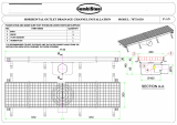
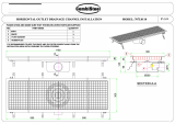
Watts Dead Level SP Installation guide

Type
Installation guide
Installation Instructions
Dead Level
®
Trench Drain
Systems
Pre-Sloped Systems - Dead Level
®
D, Dead
Level
®
DX, Dead Level
®
P
Non-Sloped Systems - Dead Level
®
S,
Dead Level
®
SP, Dead Level
®
Z
Frame & Grate Systems - Dead Level
®
DL-
GF, Dead Level
®
DLP-GF, Dead Level
®
DX-GF
Read this Manual BEFORE using this equipment.
Failure to read and follow all safety and use information can result in death,
serious personal injury, property damage, or damage to the equipment.
Keep this Manual for future reference.
WARNING
!
Local building or plumbing codes
may require modications to
the information provided. You
are required to consult the local
building and plumbing codes prior
to installation. If the information
provided here is not consistent
with local building or plumbing
codes, the local codes should be
followed. This product must be
installed by a licensed contractor
in accordance with local codes
and ordinances.
WARNING
!
NOTICE
Follow the guidelines listed here for
proper installation, operation, and
maintenance.
2
Frame
1/4-20x3/8" Hex Bolt
1"
Max.
1/2" #4 Rebar
FIG. A
1/4-20x3/8" Hex Bolt
1/2" #4 Rebar
1"
Max
Frame
General
The Dead Level
®
Trench Drain System is designed to be installed without cutting to
length in the eld. Runs can be congured and supplied in any even 12" increment.
Standard channel sections for extended runs are 48" long.
Dead Level
®
systems are generally installed on grade, poured in a concrete slab.
The anged joints connecting channel sections are not watertight, and are typically
left unsealed by the installing contractor. Please contact your Watts representative
for above grade installation options, or if sealed joints are required by specication
or local code.
Pre-Sloped Dead Level
®
D, Dead Level
®
DX, Dead Level
®
P System
Installation
1.) Dead Level
®
pre-sloped systems are packaged to arrive at the jobsite with
the channel sections attached to the frame sections. The system is designed
to be installed with the frames attached to the channels, do not separate the
channels from the frames. If the channels and frames accidentally become
separated, please contact your Watts representative for assistance.
2.) An installation diagram is supplied matching each congured run to the
corresponding assembled sections, which are sequentially labeled. The
installation diagram is normally packaged with the system hardware. If you
cannot locate the diagram, please contact your Watts representative for a
copy.
3.) Excavate a trench to allow a minimum 4" concrete pour below and on both
sides of the trench drain, and below a catch basin (if used).
4.) Work from the deepest outlet connection or catch basin back upstream.
Referring to the installation diagram, lay the trench drain sections alongside
the open trench. Each channel and frame is marked with arrows indicating
the direction of ow; conrm all arrows are pointing downstream.
5.) Establish an accurate line and grade reference using a string line or laser
level.
6.) Dead Level
®
systems can be anchored with either 1/2" #4 rebar, or
equivalent all-thread rod. Starting from the outlet or catch basin (see Catch
Basin Cutouts), set the rst section in place. Drive a minimum of 4 anchor
rods through the frame ears for each section. The required depth of anchor
rods varies with soil conditions; rods must be solidly anchored to provide
stability for the system, and prevent shifting or oating during the concrete
pour.
7.) Level each section by sliding the frame ears along the anchor rods, and
secure the frame in place with 3/8" hex bolts.
3
8.) Set the next section in place and repeat steps 6 and 7. Connect the
sections with 4 self-tapping hex bolts per section through the top and
bottom holes on the anges.
9.) Repeat steps 6 through 8 for all remaining sections until the run is
complete. For male-male channel connections, see Channel Adaptors.
Note: On extended runs you may encounter frame sections overhanging
channel sections. If this occurs, see Channel Spacers to re-align the
channels and frames.
10.) Using a 3/8"hex bolt and at washer, install the frame connectors to secure
each joint. With the ange pointing down, pull the connector tight against
the frame crossbar, and bolt the connector to the frame on the opposite
side.
11.) Attach end caps at all exposed channel ends with 4 self-tapping hex bolts.
Trim the top of each end cap along the horizontal scores ush with the top
edge of the frame (at grade).
12.) Open the desired outlet(s) with a hole or reciprocating saw, taking care not
to rake the inside wall of the hub. After removing any burrs, make a No
Hub pipe connection with a suitable coupling (by others).
13.) Install the system grates and secure each grate to the frame crossbars with
grate lockdown bolts. Hex bolt lockdowns should be installed with a at
washer.
1/4 x 1" Self-Tapping Hex Bolts
1/4" x 1" Self-Tapping Hex
Bolts
FIG. B
FIG. C
F-L
3/8" Hex Bolt
4
Ensure the grates are aligned with an equal distance to each sidewall
before tightening the bolts.
Note: Frame Guards if specified must be installed before the grates, and
prior to the concrete pour.
14.) Install the construction covers to protect the grating and prevent
construction debris from entering the channels.
Concrete Pour
1.) Check the excavation to be sure a minimum of 4" of concrete can be
poured under, and on all sides of the channels.
2.) Check the entire system for proper anchoring, alignment, leveling, and
connections. While the Dead Level
®
design dramatically reduces the risk of
oating, a poorly anchored system is likely to shift during the pour.
3.) The edge of the trench frame should be set approx. 1/16" below the
surface after the nish troweling. This will ensure the frame remains at or
below grade after the concrete is fully cured.
4.) Concrete must be adequately vibrated as it is placed, to completely ll
all potential voids around the trench system.
Catch Basin Cutouts
1.) Catch basins may ship in two pieces - attach the frame to the basin prior to
making cutouts.
2.) Invert the basin on a at surface and butt the trench section(s) shown on
the installation diagram against the pattern on the basin.
Note: Catch basins will only mate properly with the downstream end of a #5
channel section, or a neutral channel section.
FIG. D
Channel &
Frame
Frame Guards
(Optional)
Lock Down
Grates
Lockdown
Grates
Construction
Cover
Construction Cover
FIG. E
Frame Guards
(Optional)
Channel &
Frame
5
3.) After identifying the correct scored cutout line, use a reciprocating saw to
create a U-shaped opening in the basin that matches the connecting
channel. When the cutout is correctly removed, the channel tongue should
slide inside the hole in the basin, with the channel ange ush against the
basin’s exterior wall.
Corner/Tee Section Installation
1.) Note whether the connecting channel has a tongue or groove connection.
Identify the correct cutout pattern on the adjoining corner/tee section.
2.) Use a reciprocating saw to remove the cutout on the corner/tee. When
correctly removed, the channel tongue should slide inside the mating
groove on the corner/tee so the anges are ush.
3.) For corner connections, install a male end cap on the unused opening of
the corner/tee section.
Note: Corner/Tee sections will only mate properly with the downstream
end of a #5 channel section, or a neutral channel section.
Piped Corners
1.) Install the appropriate male or female end cap on each of the adjoining
sections.
2.) The end cap connections are No Hub. Install a suitable 90 degree coupling
or ttings (by others) to make a subsurface connection between the two
end caps.
3.) Open the end caps with a hole or reciprocating saw and make the connections.
FIG. F
Corner/Tee Section
Standard Section
End Cap
Standard Section
Flow
Flow
FIG. G
Corner/Tee Section
Standard Section
End Cap
Standard Section
Flow
Flow
6
Retro-Fit Installations
1.) Cut the existing concrete slab and form a cavity which will enable a 4"
concrete pour below and around the Dead Level
®
system.
2.) Cut 2x4’s at least 30" in length to span the cavity. Align the 2x4’s with the
frame cross bars, and drill 1/2" holes corresponding to the tapped holes in
the cross bars.
3.) Insert an approx. 1/16" thick shim between the frame and the 2x4’s to
ensure the trench drain will sit below the nished grade. Attach the 2x4’s
to the cross bars with 3/8" x 4 1/2" (minimum) bolts and washers.
4.) Securely anchor the 2x4’s to the surrounding slab to prevent shifting or
oating during the pour.
5.) Once the concrete is set, remove the 2x4’s and complete any unnished
areas with concrete.
6.) Install the grates, lockdowns, and construction covers.
Non-Sloped Dead Level
®
S, Dead Level
®
SP, Dead Level
®
Z System Installation
Note: Systems installed above grade must be fully encased in a concrete
slab, and waterproofed to prevent leak-through. Please contact your
Watts representative for above grade installations.
1.) Dead Level
®
non-sloped systems are designed to be installed with the
frames attached to the channels; do not separate the channels from the
frames. All sections are the same depth, and can be installed in any
sequence without regard to the direction of ow.
End Cap
Standard Section
End Cap
Standard Section
Flow
Flow
FIG. H
Standard Section
Standard Section
End Cap
End Cap
Flow
Flow
FIG. I
7
2.) For on-grade installations, follow the installation sequence for Dead Level
®
Pre-Sloped Systems.
3.) Each channel section has a 4" female IPS outlet connection. Open the
desired outlet(s) with a hole or reciprocating saw, taking care not to
damage the outlet threads. After removing any burrs, make a pipe
connection with a suitable 4" IPS nipple or tting (by others).
4.) Dead Level
®
Z systems are designed for two-stage concrete pours.
Following the initial pour, use suitable concrete fastners (by others) to
secure the anged frame to the slab through the countersunk holes. Finish
the installation with a topping pour or grout to grade.
Frame & Grate Dead Level
®
DL-GF, Dead Level
®
DLP-GF,
Dead Level
®
DX-GF System Installation
Note: Dead Level
®
Frame & Grate systems are designed for installation
on grade with cast-in-place concrete channels. Installation requirements
will vary with concrete framing preferences and jobsite conditions.
1.) Establish an accurate line and grade reference using a string line or laser
level.
2.) Dead Level
®
frames can be anchored with either 1/2" #4 rebar, or
equivalent all-thread rod. Drive a minimum of 4 anchor rods through the
frame ears of each section, and secure the rods after leveling. For ground
anchoring, the required depth of anchor rods varies with soil conditions.
Alternatively, the frames may be attached to concrete forms by other
appropriate means.
3.) Using a 3/8" hex bolt and at washer, install the frame connectors to secure
each joint. With the ange pointing down, pull the connector tight against
the frame crossbar, and bolt the connector to the frame on the opposite
side.
Tooled Joint w/Sealant
(by others)
Cast in Place
Concrete
Heavy Duty Trench
Support Flange
6"(152)
2"
(51)
1 1/2"(38)
6"
(152)
FIG. J
F-L
3/8" Hex Bolt
FIG. K
Tooled Joint w/Sealant
(by others)
Cast in Place
Concrete
Heavy Duty Trench
Support Flange
6"(152)
2"
(51)
6"
(152)
1 1/2"(38)
4.) Install the system grates and secure each grate to the frame crossbars with
grate lockdown bolts. Hex bolt lockdowns should be installed with a at
washer. Ensure the grates are aligned with an equal distance to each
sidewall before tightening the bolts.
Note: Frame Guards if specified they must be installled before the grates
and prior to the concrete pour.
5.) Install the construction covers to protect the grating and prevent
construction debris from entering the channels.
Channel Adaptors
A Channel Adaptor is required to make male-male connections (channels sloping
towards each other). Install the U-shaped adaptor between the two male ends and
cut along the scored lines to match the height of the connecting channels. Secure
the adaptor with 4 sets of 10-24 bolts and nuts provided. A matching block is
provided with each adaptor to ll the gap created between the installed grates.
Trim the block along the scored lines to match the nished grade, and secure the
block to the frame crossbar with 3/8" hex bolts and flat washers.
Note: Female-female connections (channels sloping away from each other)
attach directly and do not require an adaptor. If desired the installer can fill the
slight recess created on the inside of the connection with a bead of silicone
caulk.
Channel Spacers
Under certain conditions the cumulative frame length may exceed the cumulative
channel length, resulting in the frame overhanging the channel. If this occurs, insert
3/4” wide U-Shaped male-female Channel Spacers to extend the channel length to
match the frame length. Channel spacers can be added as needed at any point in
a run.
8
Channel Adaptor
Block
FIG. L
Channel Spacer
Overhanging Frame
Channel Retention Clips
Under certain conditions or due to handling, Dead Level
®
channel sections may
ex-out, causing the channels to disengage from the frames. If this occurs, Channel
Retention Clips can be installed on the anchor rods to hold the channels in place.
Please contact your Watts representative if additional retention clips are required.
Channel Retention Clip
The Clip On 12" DI Frame
Engages The Channel Against
The Top Lip
The Clip on 6" Poly Frame Engages
The Channel Against the Side
Underneath the Lip
The Clip on 6" DI Frame Engages
The Channel Against the Side
Underneath The Lip
Dead Level
®
D Dead Level
®
P Dead Level
®
DX
Limited Warranty: Watts (the “Company”) warrants each product to be free from defects in material and workmanship
under normal usage for a period of one year from the date of original shipment. In the event of such defects within the
warranty period, the Company will, at its option, replace or recondition the product without charge.
THE WARRANTY SET FORTH HEREIN IS GIVEN EXPRESSLY AND IS THE ONLY WARRANTY GIVEN BY THE COMPANY
WITH RESPECT TO THE PRODUCT. THE COMPANY MAKES NO OTHER WARRANTIES, EXPRESS OR IMPLIED. THE
COMPANY HEREBY SPECIFICALLY DISCLAIMS ALL OTHER WARRANTIES, EXPRESS OR IMPLIED, INCLUDING BUT NOT
LIMITED TO THE IMPLIED WARRANTIES OF MERCHANTABILITY AND FITNESS FOR A PARTICULAR PURPOSE.
The remedy described in the first paragraph of this warranty shall constitute the sole and exclusive remedy for breach
of warranty, and the Company shall not be responsible for any incidental, special or consequential damages, including
without limitation, lost profits or the cost of repairing or replacing other property which is damaged if this product does not
work properly, other costs resulting from labor charges, delays, vandalism, negligence, fouling caused by foreign material,
damage from adverse water conditions, chemical, or any other circumstances over which the Company has no control.
This warranty shall be invalidated by any abuse, misuse, misapplication, improper installation or improper maintenance or
alteration of the product.
Some States do not allow limitations on how long an implied warranty lasts, and some States do not allow the exclusion
or limitation of incidental or consequential damages. Therefore the above limitations may not apply to you. This Limited
Warranty gives you specific legal rights, and you may have other rights that vary from State to State. You should consult
applicable state laws to determine your rights. SO FAR AS IS CONSISTENT WITH APPLICABLE STATE LAW, ANY IMPLIED
WARRANTIES THAT MAY NOT BE DISCLAIMED, INCLUDING THE IMPLIED WARRANTIES OF MERCHANTABILITY AND
FITNESS FOR A PARTICULAR PURPOSE, ARE LIMITED IN DURATION TO ONE YEAR FROM THE DATE OF ORIGINAL
SHIPMENT.
IS-WD-DL-Installation 2032 EDP# 2915867 © 2020 Watts
USA: T: (800) 338-2581 • F: (828) 248-3929 • Watts.com
Canada: T: (888) 208-8927 • F: (888) 479-2887 • Watts.ca
Latin America: T: (52) 55-4122-0138 • Watts.com
NOTICE
Inquire with governing authorities for local installation
requirements
  • Page 1 1
  • Page 2 2
  • Page 3 3
  • Page 4 4
  • Page 5 5
  • Page 6 6
  • Page 7 7
  • Page 8 8
  • Page 9 9
  • Page 10 10
  • Page 11 11
  • Page 12 12
  • Page 13 13
  • Page 14 14
  • Page 15 15
  • Page 16 16
  • Page 17 17
  • Page 18 18
  • Page 19 19
  • Page 20 20
  • Page 21 21
  • Page 22 22
  • Page 23 23
  • Page 24 24
  • Page 25 25
  • Page 26 26
  • Page 27 27

Watts Dead Level SP Installation guide

Type
Installation guide

Ask a question and I''ll find the answer in the document

Finding information in a document is now easier with AI