Page is loading ...

INSTRUCTIONS
STRP-LED™ INSTALLATION
RAB Lighting is committed to creating high-quality, a ordable, well-designed and energy-e cient LED lighting and controls that make it easy for electricians to install
and end users to save energy. We’d love to hear your comments. Please call the Marketing Department at 888-RAB-1000 or email: [email protected]
Fig: 1
Fig: 2
IMPORTANT
READ CAREFULLY BEFORE INSTALLING FIXTURE. RETAIN THESE INSTRUCTIONS FOR FUTURE REFERENCE.
RAB xtures must be wired in accordance with the National Electrical Code and all applicable local codes. Proper grounding is
required for safety. THIS PRODUCT MUST BE INSTALLED IN ACCORDANCE WITH THE APPLICABLE INSTALLATION CODE BY A PERSON
FAMILIAR WITH THE CONSTRUCTION AND OPERATION OF THE PRODUCT AND THE HAZARDS INVOLVED.
WARNING: Disconnect or turn OFF power at the electrical panel before installing or maintaining xture. No User serviceable
parts inside xture.
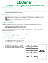
SURFACE MOUNTING
The xture is suitable for indoor applications for ceiling mounting,
as follows:
1. Remove LED Cover by pushing in/squeezing the xture’s sides
and lifting the LED Cover to disengage.
2. Locate the line voltage input wires near one of the Knockouts.
Remove the corresponding Knockout to access the xture’s leads.
Pull supply wires through the Knockout and secure with proper
hardware (by others) .
3. Securely mount the Housing directly to a sturdy surface using
the correct mounting hardware through the Drill Locations, (2
places minimum). See Fig.1. The J-Box Adapter (ordered separately
as JBSTRP, on 4’ units only) is used to cover the Junction Box (by
others).
4. Use correct UL-rated wire connectors as required by the National
Electric Code to make electrical splices to xture leads.
5. Connect the Connectors, tidy up the leads, and secure the LED
Cover to the Housing.
WARNING: To prevent wiring damage or abrasion, do not expose
wiring to sharp objects.
STRP210
Housing
J-Box Adapter
(Accessory)
LED Cover
Connectors
Knockout
(2 ft con gurations
missing center knockout)
Drill Locations
STRP220STRP420 STRP440
Connector
SUSPENDED MOUNTING
The xture can be mounted using S-hooks (ordered separately as
STRP SHOOK).
1. Mount S-hooks (two S-hooks for the single tube, four S-hooks for the
double tube) to the xture as shown in Fig. 2.
2. For electrical wiring, follow steps 1, 2, and 4 above.
S-Hooks

INSTRUCTIONS
STRP-LED™ INSTALLATION
RAB Lighting is committed to creating high-quality, a ordable, well-designed and energy-e cient LED lighting and controls that make it easy for electricians to install
and end users to save energy. We’d love to hear your comments. Please call the Marketing Department at 888-RAB-1000 or email: [email protected]
CONTINUOUS RUN MOUNTING
Joiner
Connector
Fixture
Fig. 3
010V DIMMABLE WIRING
CLEANING & MAINTENANCE
TROUBLESHOOTING
Note: These instructions do not cover all details or variations in equipment nor do they provide for every possible situation during installation, operation or maintenance.
Multiple xtures can be mounted together:
1. For continuous runs, remove Joiner Port cover. Plug together
Fixtures using the Joiner Connector between xtures for quick
connect installation (Fig. 3). Only the rst Fixture needs to be
electrically hardwired from above. For suspended mount, join
every two adjacent Fixtures by attaching a Plate using four
screws as shown in Fig. 3. If surface mounted, all joined Fixtures
must be mechanically secured to the mounting surface and are
not required to be attached to a Plate with four screws.
2. NOTE: The Joiner Port at each end of the Fixtures is marked “A”
or “B”, please note that the “A” connector must be inserted in to
the “B” end of the following xture and vice versa.
3. CAUTION: The maximum number of xtures allowed to be
linked together is indicated in the below table. xx represents
color temperature 3500K and may be replaced by 40 (4000K)
or 50 (5000K).
WARNING: To prevent wiring damage or abrasion, do not expose
wiring to sharp objects.
RISK OF FIRE. Universal voltage driver permits operation at
120V thru 277V, 50 or 60 Hz. For 0-10V dimming, follow the wiring
directions in Fig. 4.
1. Connect the black xture lead to the LINE supply lead.
2. Connect the white xture lead to the COMMON supply lead.
3. Connect the green GROUND wire from xture to supply ground.
4. Connect the purple xture lead to the (V+) DIM lead.
5. Connect the gray xture lead to the (V-) DIM lead.
6. Cap the yellow xture lead, if present. Do NOT connect.
Fig. 4
CAUTION: Be sure xture temperature is cool enough to touch.
Do not clean or maintain while xture is energized.
1. Clean polycarbonate lens with non-abrasive cleaning solution.
2. Do not open the xture to clean the LEDs. Do not touch the
LEDs.
1. Check that the line voltage at the xture is correct. Refer to
wiring directions in Fig. 4.
2. Be sure the xture is grounded properly.
Plate
Fixture
Catalog #
STRP210-8xx
STRP220-8xx
STRP420-8xx
STRP440-8xx
Maximum Number of Linked Fixtures
Up to 30 xtures
Up to 25 xtures
Up to 25 xtures
Up to 15 xtures
Joiner Port
STRPLED-IN 1218
Easy Answers
rablighting.com
Visit our website for product info
Tech Help Line
Call our experts: 888 722-1000
e-mail
Answered promptly - [email protected]
Free Lighting Layouts
Answered online or by request
© 2018 RAB LIGHTING Inc.
Northvale, New Jersey 07647 USA
RAB WARRANTY: RAB’s warranty is subject to all terms and conditions found at rablighting.com/warranty.
/