INSTALLATION INSTRUCTIONS
DL25
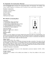
Dinky Link™ Surface Mount
Standard IR Receiver
1
DESCRIPTION
These small IR receivers have been designed for mounting in very small
spaces. They may be mounted under shelf edges, cabinet ledges, in wall
speakers, etc. – anywhere an inconspicuous appearance is desired. The high
sensitivity of these receivers allows placement behind speaker grilles and still
receive IR commands up to 60 feet away*.
FEATURES
• Wire channel for clean installation.
• System testing red-talk-back LED.
• Includes 3-Terminal Block for easy extension to remote room locations.
SPECIFICATIONS
• Infrared carrier frequency bandwidth: 30 - 60 kHz.
• Reception range: Up to 60 feet.*
• Reception angle: +/- 60 degrees.
• Cable requirements: See “INSTALLATION” below.
• Max. Transmission length: 1 mile using 18 gauge wire.
• Maximum current output: 100mA.
• Drives IR emitters through Xantech Connecting Blocks, Controllers, etc.
• Dimensions: 2.55” x 0.55” x 0.35” (65mm x 14mm x 9mm).
• Power requirements: +12VDC, 10mA.
* Depending on remote control output strength and ambient conditions.
MOUNTING
The IR receiver can be mounted to any flat surface, using the two-sided
adhesive tape supplied. Two screws are included for mounting the 3-terminal
block provided with the IR receiver.
An additional feature is a wire channel on the rear of the surface mount IR
receiver. This will give the installer the ability to provide clean wire dressing in
any direction.

2
INSTALLATION
IR RECEIVER CABLE WIRING
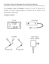
REMOTE ROOM APPLICATION
One application is to locate the IR receiver in a remote room. This will give the
end-user the ability to control audio/video equipment from a location where
the remote control no longer has the ability of direct line-of-sight.
The IR receiver will need the 3.5mm stereo type mini plug removed to extend
the wire run to the connecting block. A 3-terminal block is supplied to connect
the IR receiver to the connecting block with a 3-conductor inter-room cable in
between. The 3-conductor inter-room cable (24 gauge up to 200’, 22 gauge
up to 600’, 20 gauge up to 2000’, 18 gauge up to 5000’), is run to the main
room.
D
L Series
IR Receiver
White
Stripe
3-Terminal Block
3-Conductor
Wire to Controlled
Equipment
7-Foot Ribbon Cable
with Mini Plug removed
OUT
+12V
GND
DL Series
IR Receiver
Red (or white)
Stripe
To 120 V AC
(unswitched)
781ERGPS
789-44
Connecting Block
REMOTE ROOM
MAIN ROOM
Hand Hel d
Remote
3-Terminal Block (supplied )
3-Conductor
Inter-room Cable
(unshielded OK)
7' Ribbon Cable
A/V Receiver
DVD
IR Photodiode
Red
Talkba ck LED
Satellite Receiver
283D Emitter
12VD C
+12 VDC
GND
STATUS
IR IN
EMITTERS
IR
RCVR
789-44
CONNECTING BLOCK
®
IR OUT
+12V
GND
283D Emitter
283D Emitter
3
Input connections must be made as illustrated. To extend the emitter wires to
a more distant location, you may splice in 2-conductor wire, in the wire
gauges mentioned before, as needed.
While it is possible to make wired connections without the connecting block, it
is not recommended. The connecting block reduces installation time, helps to
eliminate errors, allows easy troubleshooting and permits easy system
upgrades later, if needed.
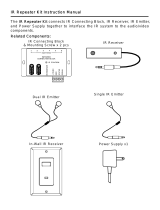
LOCAL SYSTEM APPLICATION
Another application is to locate the IR receiver in a central location, such as
the TV, video screen and/or a speaker. The audio/video equipment can then
be hidden inside a cabinet or located away from the front of a room. This will
give the end-user the ability to direct a remote control to one central location
and not have to worry about aiming to the respective device to be controlled.
The IR receiver is in close proximity to the audio/video equipment, no wiring
extension should be required so long as the connecting block is within reach
of the 7-foot cable. The 3.5mm stereo type mini plug is connected to the “IR
RCVR” jack on the Xantech Connecting Block.
PLACEMENT
The IR receiver should be located so that it is not directly facing a light source
such as lamps or displays (standard, LCD, and Plasma). When mounted near
a display, it should be flush to the display and away from light reflections that
may occur.
To 120 V AC
(unswitched)
Emitter
Emitter
7 Foot Ribbon
Cable with Quick
Connect Mini Plug
Controlled Equipment
(mounted behind
closed cabinet doors)
(mounted on or
near cabinet in an
inconspicuous
location).
Emitter
Emitter
Satellite Receiver
VCR
AV Receiver
CD Changer
Cassette Deck
DL Series
IR Receiver
Hand Hel
d
Remote
IR Photodi ode
Red
Talkb ack LED
791-44
Amplified
Connecting Block
+ 12 V D C
GN D
EMITTERS
12 VDC
HIGH
IR
OUT
S TAT US
I R I N
IR
RCVR
791- 44
AMPLIFIE D
CONNECTING BLOCK
®
781ERGPS
Emitter

4
TROUBLE SHOOTING:
1. Perhaps the most common problem you may encounter is stray IR
(infrared) or RF (radio frequency) interference preventing proper
operation of the controlled equipment.
• Fluorescent, Compact Fluorescent, Neon or Halogen lights,
Neon Art, and light dimmers.
• Direct or reflected sunlight.
• Infrared security sensors (active types).
• RF radiation from TV sets that may be close to the Dinky Link
IR Receiver.
2. You can confirm the source of the interference by temporarily turning
off TV sets, isolating the Dinky Link IR Receiver from all sunlight and
turning off all lights, light dimmers and Infrared security systems.
Then check to see if the Dinky Link IR Receiver operates the
component.
• Sometimes interference will cause the red Talk-Back LED on
the front of the Dinky Link IR Receiver to blink dimly,
intermittently, or continuously.
• The Talk-Back Led should only blink when you are sending
infrared commands to the Dinky Link IR receiver from a
remote control.
• It may be necessary to move either the interfering source of
the Dinky Link IR Receiver to achieve proper operation.
3. If the Talk-Back LED or the 283D Emitters do not blink when you are
sending IR commands to the Dinky Link IR Receiver from a remote
control, check the following:
• Make sure the power supply is plugged securely into a live
AC electrical outlet.
• Be sure the stereo mini plug of the Dinky Link IR Receiver is
plugged into the “IR RCVR” jack on the CB12 Connecting
Block, not into the “OUT” jack.
• Check to see that all the mini plugs are properly seated into
the mini jacks on the CB12 Connecting Block.
4. If the 283D Emitters blink, but the component does not respond,
reposition the 283D Emitter(s). They may not be located directly over
the component’s infrared receiving “window”. Consul the owner’s
manual of the unit or the manufacturer for the exact location of the
infrared “window”.
5
Limited Warranty
Xantech® warrants its products to be free of defects in materials or workmanship. This is a
Limited Lifetime warranty from the date of purchase by the original consumer. Any products
returned to Xantech and found to be defective by Xantech within the warranty period will be
repaired or replaced, at Xantech’s option, at no charge. Xantech will not be responsible for the
actual cost of installation or removal of the product, nor for any incidental or consequential
damages. Some states do not allow the exclusion or limitation of incidental or consequential
damages, so the above limitation may not apply to you. This warranty gives you specific legal
rights. You may have additional legal rights that vary from state to state.
Xantech Corporation
13100 Telfair Ave., Sylmar CA 91342 | Xantech.com
Installation Instructions, DL25 © 2009 Xantech Corporation
Document # 08905291B
This document is copyright protected. No part of this manual may be copied or reproduced in any
form without prior written consent from Xantech Corporation. Xantech Corporation shall not be
liable for operational, technical, or editorial errors/omissions made in this document.
/