Page is loading ...

FocusPRO
®
Wireless Thermostats
® U.S. Registered Trademark.
Copyright © 2011 Honeywell International Inc.
All rights reserved.
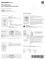
Installation
Guide
69-2092EFS-07
Wireless control for up to 3 Heat/2 Cool heat pump systems or up to 2 Heat/2
Cool conventional systems.
MERCURY NOTICE: If this product is replacing a control that contains mercury in
a sealed tube, do not place the old control in the trash. Contact your local waste
management authority for instructions regarding recycling and proper disposal.
Must be installed by a trained, experienced technician. Read these
instructions carefully. Failure to follow these instructions can damage the product or
cause a hazardous condition.
Français : voir la page 9 • Español: vea la página 17
Installation guide for:
Non-zoned systems
• Singlethermostatwithwireless
Equipment Interface Module
(EIM)
Zoned systems
• Upto4thermostatswith
TrueZONE™ panel & wireless
adapter.
Need Help?
For assistance with this product please visit http://customer.honeywell.com
or call Honeywell Customer Care toll-free at 1-800-468-1502

FocusPRO
®
Thermostat Installation Guide
69-2092EFS—07 2
M28474
1
Install batteries
2
Link thermostat(s) to wireless network
M28472
M28473
Install 2 fresh AA batteries
Install quick reference card
Programmable models only
M28497
0
1
Wireless Setup
Next
M28478
36
52
Wireless Setup
Next
Back
M28479
Wireless Setup
Connect
Back
M28480
Wireless Setup
Connected
Done
Zone number Zone name
Installation with EIM: Press NEXT (leave
zone number set to zero).
Installation with TrueZONE panel: Press s
or t to set a zone number for this ther-
mostat(1to4),thenpressNEXT.
Installation with EIM: Press NEXT.
Installation with TrueZONE panel: Press s
or t to select a name for this zone, then
press NEXT(seelistofnamesonpage6).
Press CONNECT to establish a link to the wire-
less network.
If E1 appears, see error codes on page 3.
After a brief pause, the confirmation screen
at left should be displayed, to verify that the
wireless connection has been established.
Press DONE to display the home screen.
Press and release the CONNECT button at EIM or wireless adapter and wait for green
flashing light, then follow steps below.

Français : voir la page 9 • Español: vea la página 17
3 69-2092EFS—07
3
Customize thermostat (installer setup)
Follow the steps below to begin installer setup. At each function screen, press
s or t to change the setting as desired, then press NEXT to advance to the
next function screen.
Seetablesonpages4-6foradescriptionofoptionsforeachfunction.
Press s or t to change set-
ting(seetablesonpages4-6).
Press NEXT to display next
function screen.
FAN
M28485
To begin, press and hold the FAN and s buttons
until the display changes (about 3 seconds).
Function
Press DONE to save & exit.
Setting
M28498
0
1
Next
Back
Done
M28487
1
0
Next
Back
Done
M28488
If E1 or E appears, check error code number (right side of screen):
23 EIM does not have dual fuel capability. Replace EIM if you have fossil fuel backup heat
orchangeInstallerSetupFunction4toELECTRICifyouhaveelectricbackupheat
(seepages3-5).
29 You are attempting to connect a thermostat to an incompatible device.
30 Zone number must match zone panel number (must be zero for EIM systems).
31 Verify that this zone number is configured at the zone panel as an RF thermostat.
33 Check Return Air Sensor wiring. If removing the sensor permanently, press and hold the
CONNECT button on the EIM for 10 seconds (until flashing orange) to clear this error code.
See page 8, then page 2 to reconnect thermostat.
34 Lowsignalstrength.Movewirelessdevicetoadifferentlocationandtryagain.
38 Make sure Connected light on EIM or wireless adapter is flashing and you are 2+
feet away from EIM or wireless adapter.
53 Thermostat is not receiving Outdoor Temperature and Outdoor Humidity:
1. Thermostat may be configured for dual fuel, compressor lockout or auxiliary lockout
with no outdoor sensor. Follow Wireless Setup procedure to connect outdoor sensor
to the EIM.
2.IfE53continues,outdoorsensormaynotbecommunicating.Install2freshAA
Lithiumbatteriesintheoutdoorsensor.
Thermostat error codes

FocusPRO
®
Thermostat Installation Guide
69-2092EFS—07 4
Installer setup tables
Setup function Settings & options (factory default in bold)
0 Zone number 0 Nozoning(singlethermostatusedwithTHM5320REIM)
[Options:selectzone1,2,3or4]
1 System type 0 1 heat/1 cool conventional
1 1 heat/1 cool heat pump (no aux. heat)
2 Heat only (includes Series 20)
3 Heat only with fan
4 Coolonly
5 2heat/1coolheatpump
6 2heat/2coolconventional
7 2 heat/1 cool conventional
8 1 heat/2 cool conventional
9 2 heat/2 cool heat pump
10 3 heat/2 cool heat pump
2 Changeover valve
(O/B terminal)
0 O/B terminal controls valve in cooling
1 O/B terminal controls valve in heating
3 Fan control
(conventional heat)
0 Gas/Oil heat (equipment controls fan)
1 Electric furnace (thermostat controls fan)
4 Backup heat
(EIM only)
1 Electric backup heat
0 Fossil fuel backup heat
5 Stage 1 heat cycle
rate (CPH: cycles per
hour)
5 Gas or oil furnaces (less than 90% efficiency)
1 Steam or gravity systems
3 Hot water systems & furnaces of over 90% efficiency
9 Electric furnaces
[Cyclerateoptions:1to12CPH]
6 Stage 2 heat cycle
rate (CPH)
5 Gas or oil furnaces (less than 90% efficiency)
1 Steam or gravity systems
3 Hot water systems & furnaces of over 90% efficiency
9 Electric furnaces
[Cyclerateoptions:1to12CPH]
7 Stage 3 heat cycle
rate (CPH)
5 Gas or oil furnaces (less than 90% efficiency)
1 Steam or gravity systems
3 Hot water systems & furnaces of over 90% efficiency
9 Electric furnaces
[Cyclerateoptions:1to12CPH]
8 Emergency heat cycle
rate (CPH)
9 Electric furnace
[Cyclerateoptions:1to12CPH]
9 Stage 1 compressor
cycle rate
3 Recommended cycle rate
[Cyclerateoptions:1to6CPH]
10 Stage 2 compressor
cycle rate
3 Recommended cycle rate
[Cyclerateoptions:1to6CPH]
11 Heat pump type
(EIM only)
0 Air to Air Heat Pump
1 Geothermal heat pump
12 Manual/Auto
changeover
0 Manual (User options: Heat/Cool/Off)
1 Automatic (User options: Heat/Cool/Auto/Off)
13 Adaptive Intelligent
Recovery™
AppliesonlytoModelTH6320
0 Off
1 On
14 Temperature
display
0 Fahrenheit
1 Celsius
15 Compressor off time 5 5 minutes (Heat On/Cool On flashes during off time)
[Options:0to4minutes]
16 Schedule format
AppliesonlytoModelTH6320
0 Weekday/weekend program schedule
1 Weekday/Saturday/Sunday program schedule

Français : voir la page 9 • Español: vea la página 17
5 69-2092EFS—07
17 External fossil fuel kit
(EIM only)
1 External fossil fuel kit controls backup heat
0 Thermostat controls backup heat (outdoor sensor required)
18 Dual fuel heat pump
control (EIM only)
1 Droop control**
0 No droop control**
2 DroopcontrolwithAuxHeatLockout**
20 Droop temperature
(dual fuel) (EIM only)
2 Auto temperature droop 2° F (1° C)
[Options:2to5(2to5°F/1to2.5°C)]
21 Dual fuel upstage to
furnace timer (EIM
only)
1 1 hour**
[Options:0(off)to16hours]
22 Outdoor air sensor?
(EIM only)
0 No
1 Yes
24 Heat pump
compressor lockout
(balance point) (EIM
only)
0 No heat pump compressor lockout**
1 5°F(-15°C) 7 35°F(1.5°C)
2 10°F(-12°C) 8 40°F(4.5°C)
3 15°F(-9.5°C) 9 45°F(7°C)
4 20°F(-6.5°C) 10 50°F(10°C)
5 25°F(-4°C) 11 55°F(13°C)
6 30°F(-1°C) 12 60°F(15.5°C)
25 Heat pump
auxiliary lockout
(EIM only)
0 No heat pump auxiliary lockout**
1 5°F(-15°C) 8 40°F(4.5°C)
2 10°F(-12°C) 9 45°F(7°C)
3 15°F(-9.5°C) 10 50°F(10°C)
4 20°F(-6.5°C) 11 55°F(13°C)
5 25°F(-4°C) 12 60°F(15.5°C)
6 30°F(-1°C) 13 65°F(18.5°C)
7 35°F(1.5°C)
26 Auxiliary heat control
AppliesonlytoModelTH6320
0 Comfort**
1 Economy
27 Maximum heat
setpoint
90 Max. heat temperature setting is 90° F (32° C)
[Options:40°Fto90°F(4.5°Cto32°C)]
28 Minimum cool
setpoint
50 Min. cool temperature setting is 50° F (10° C)
[Options:50°Fto99°F(10°Cto37°C)]
32 Temp. display offset
(indoor)
0 Thermostat displays actual temperature
[Options:-3to+3°Foffset(-1.5to+1.5°C)]
33 Temp. display offset
(outdoor)
0 Thermostat displays actual temperature
[Options:-5to+5°Foffset(-2.5to+2.5°C)]
35 Humidity display
offset (outdoor)
3 Thermostat displays actual humidity
[Otheroptions:0=-15%,1=-10%,2=-5%,4=+5%,
5=+10%,6=+15%offset]
Installer setup tables
Setup function Settings & options (factory default in bold)
** See page 6

FocusPRO
®
Thermostat Installation Guide
69-2092EFS—07 6
36 Zone name 52 Thermostat
1 Basement 16ExerciseRoom 30Library 44Porch
2 Bathroom 17 Family Room 31LivingRoom 45RecRoom
3 Bathroom 1 18 Fireplace 32LowerLevel 46SewingRoom
4Bathroom2 19 Foyer 33 Master Bath 47Spa
5Bathroom3 20 Game Room 34MasterBed 48StorageRoom
6Bedroom 21 Garage 35MediaRoom 49Studio
7 Bedroom 1 22 Great Room 36MusicRoom 50SunRoom
8 Bedroom 2 23 Guest Room 37 Nursery 51Theater
9 Bedroom 3 24Gym 38 Office 52Thermostat
10Bedroom4 25Kid'sRoom 39 Office 1 53UpperLevel
11 Boat House 26Kitchen 40Office2 54UtilityRoom
12 Bonus Room 27Kitchen1 41Pantry 55WalkInCloset
13 Computer Room 28Kitchen2 42PlayRoom 56WineCellar
14Den 29LaundryRoom 43PoolRoom 57Workshop
15DiningRoom
39 Wireless setup 0 Disconnect thermostat from wireless system
1 Thermostat is connected to wireless system
90 RESET 0 No reset
1 Reset installer options & program schedule to factory default
settings
Installer setup tables
Setup function Settings & options (factory default in bold)
Special functions
Heat Pump Control — Fossil Fuel Backup (Setup Function 18):
Note: If temperature is not reached in a reasonable time, set the upstage to furnace timer
(function 21). After the designated time, the compressor will turn off and the system will switch
to back up heat.
Heat Pump Control — Electric Backup (Setup Functions 24-25):
40
55
M28705
COMPRESSOR LOCKOUT
AUXILIARY LOCKOUT
COMPRESSOR AND FAN ONLY
COMPRESSOR AND FAN OPERATE
ELECTRIC BACKUP HEAT AND FAN ONLY
OUTDOOR TEMP.
IF THE COMPRESSOR CANNOT REACH OR MAINTAIN TEMPERATURE SETTING,
BOTH THE COMPRESSOR AND ELECTRIC BACKUP HEAT WILL OPERATE.
1
1
M28706
IF ROOM TEMPERATURE DROPS (EXCEEDS DROOP SETTING AT FUNCTION 20), COMPRESSOR IS DEACTIVATED. FOSSIL FUEL
BACKUP HEAT IS ACTIVATED AFTER 3 MINUTE DELAY.
1
FOR GEOTHERMAL HEAT PUMPS, THE BALANCE POINT CAN BE DISABLED AT SETUP FUNCTION 24.
**
OPTION 0: NO DROOP CONTROL
40
BALANCE
POINT **
COMPRESSOR AND
FAN ONLY
FOSSIL FUEL
BACKUP HEAT ONLY
OUTDOOR TEMP.
OPTION 1: DROOP CONTROL
OUTDOOR TEMP.
40
BALANCE
POINT **
COMPRESSOR AND
FAN OPERATE
FOSSIL FUEL
BACKUP HEAT ONLY
1
OPTION 2: DROOP CONTROL WITH AUX HEAT LOCKOUT
COMPRESSOR AND FAN OPERATE
OUTDOOR TEMP.
40
55
BALANCE
POINT **
AUXILIARY
LOCKOUT
COMPRESSOR AND FAN ONLY
FOSSIL FUEL BACKUP HEAT ONLY
1
Comfort/Economy — Setup Function 26 (Not available when Setup Function 17 is set to 0):
If you choose Comfort, auxiliary heat will respond quickly to meet the temperature
setpoint. If you choose Economy, the system will wait longer. Auxiliary heat will be
activated only if the setpoint is not reached within a reasonable time.

Français : voir la page 9 • Español: vea la página 17
7 69-2092EFS—07
System test
Follow the procedure below to test for proper operation.
M28488
To begin, press and hold the s and t buttons
until the display changes (about 3 seconds).
Press s or t to check system status
Press NEXT to advance to next test
Press DONE to terminate system test
M28489
02
0
Next
Back
Done
System test number System status
System test System status
02 Wireless test
0 Off
1 Test radio signal (after a brief pause, screen displays 1-10 to show
signalstrength;5orhigherrecommended)
04 Return air sensor
Screen displays return air temperature if device is installed and
working properly (EIM only)
10 Heating system
0 Heat and fan turn off.
1 Heat turns on
2 Stage 2 heat turns on
3 Stage 3 heat turns on
20 Emergency heating
system
0 Heat and fan turn off
1 Heat and fan turn on
30 Cooling system
0 Compressor and fan turn off
1 Compressor and fan turn on
2 Stage 2 compressor turns on
40 Fan system
0 Fan turns off
1 Fan turns on
70 Thermostat information
(for reference only)
71 Software revision number (major revisions)
72 Software revision number (minor revisions)
73 Configuration identification code (major)
74 Configuration identification code (minor)
75 Productionconfiguration date code (week)
76 Productionconfiguration date code (year)
CAUTION: EQUIPMENT DAMAGE HAZARD. Compressor protection (minimum
off time) is bypassed during testing. To prevent equipment damage, avoid cycling
the compressor quickly.

FocusPRO
®
Thermostat Installation Guide
Honeywell International Inc.
1985DouglasDriveNorth
GoldenValley,MN55422
http://customer.honeywell.com
Automation and Control Solutions
® U.S. Registered Trademark.
© 2011 Honeywell International Inc.
69-2092EFS—07M.S.Rev.06-11
Printed in U.S.A.
HoneywellLimited-HoneywellLimitée
35DynamicDrive
Toronto,OntarioM1V4Z9
4
Mount thermostat
M28490
3/16"holesfordrywall
7/32"holesforplaster
Wall anchor
Detach wallplate
Mounting screw
Wallplate
Replacing system components
To replace a thermostat, install batteries and follow the procedures on page 2 to link it to
thewirelessnetwork.Ifnecessary,modifysettingsasneeded(seetablesonpages4-6).
After installing a new EIM or zone panel, you must re-set the thermostat to communicate
with the new EIM or zone panel, as described below.
1 Press and holdthethermostat'sFAN and s buttons for 3 seconds.
2 Press BACK twice to display Function 39 (wireless setup).
3 Press t to change Function 39 setting to 0 (disconnect from old system).
4 Followtheproceduresonpage2torelinktonewsystem.

Guide d’installation
69-2092EFS—07 14
36 Nom de la zone 52 Thermostat
1 Basement 16ExerciseRoom 30Library 44Porch
2 Bathroom 17 Family Room 31LivingRoom 45RecRoom
3 Bathroom 1 18 Fireplace 32LowerLevel 46SewingRoom
4Bathroom2 19 Foyer 33 Master Bath 47Spa
5Bathroom3 20 Game Room 34MasterBed 48StorageRoom
6Bedroom 21 Garage 35MediaRoom 49Studio
7 Bedroom 1 22 Great Room 36MusicRoom 50SunRoom
8 Bedroom 2 23 Guest Room 37 Nursery 51Theater
9 Bedroom 3 24Gym 38 Office 52Thermostat
10Bedroom4 25Kid'sRoom 39 Office 1 53UpperLevel
11 Boat House 26Kitchen 40Office2 54UtilityRoom
12 Bonus Room 27Kitchen1 41Pantry 55WalkInCloset
13 Computer Room 28Kitchen2 42PlayRoom 56WineCellar
14Den 29LaundryRoom 43PoolRoom 57Workshop
15DiningRoom
39 Configuration
sans fil
0 Débrancherlethermostatduréseausansfil
1 Thermostat relié au réseau sans fil
90 RÉARMER 0 Pas de réarmement
1 Réarmerlesoptionsdel’installateuretleprogrammeauxréglages
de l’usine
Tableaux de configuration par l’installateur
Fonctions Options (réglagesdel’usineen gras)
Fonctions spéciales
Confort/Économie — configuration de la fonction 26 (N’est pas disponible lorsque la
fonction 17estrégléeà0) :Enmodeconfort,lechauffageauxiliaireréagirarapidementpour
atteindrelepointdeconsignedetempérature.Enmodeéconomie,lesystèmeattendraplus
longtemps.Lechauffageauxiliaireneseraactivéquesilepointdeconsignen’estpasatteintau
bout d’un temps raisonnable.
Régulation de la thermopompe — Chauffage d’appoint au combustible fossile
(fonctions de configuration 18):
Remarque:Silepointdeconsignen’estpasatteintenunlapsdetempsraisonnable,régler
lechauffaged’appointàlaminuteriedel’appareildechauffage(fonction21).Aprèslapériode
désignée,lecompresseurs’arrêteraetlesystèmepasseraaumodedechauffage.
Régulation de la thermopompe — Chauffage d’appoint à l’électricité (fonctions de
configuration 24-25):
40
55
MF28705
MISE SOUS SÉCURITÉ DU COMPRESSEUR
MISE SOUS SÉCURITÉ DU CHAUFFAGE AUXILIAIRE
COMPRESSEUR ET VENTILATEUR SEULEMENT
LE COMPRESSEUR ET LE VENTILATEUR FONCTIONNENT
CHAUFFAGE D’APPOINT À L’ÉLECTRICITÉ ET VENTILATEUR SEULEMENT
TEMP. EXTÉRIEURE
SI LE COMPRESSEUR NE PEUT ATTEINDRE OU MAINTENIR LA TEMPÉRATURE DE CONSIGNE, LE
COMPRESSEUR ET LE SYSTÈME DE CHAUFFAGE D’APPOINT FONCTIONNERONT TOUS DEUX.
1
1
MF28706
SI LA TEMPÉRATURE AMBIANTE BAISSE (DÉPASSEMENT DU RÉGLAGE DE L’ÉCART À LA FONCTION 20), LE COMPRESSEUR EST
DÉSACTIVÉ. LE CHAUFFAGE D’APPOINT AU COMBUSTIBLE FOSSILE EST ACTIVÉ APRÈS 3 MINUTES.
1
POUR LES THERMOPOMPES GÉOTHERMIQUES, LE POINT D’ÉQUILIBRE PEUT ÊTRE MIS EN SERVICE À LA FONCTION 24.
**
OPTION 0: RÉGLAGE DE L’ÉCART
40
POINT
D’ÉQUILIBRE**
COMPRESSEUR ET
VENTILATEUR SEULEMENT
CHAUFFAGE D’APPOINT
AU COMBUSTIBLE
FOSSILE SEULEMENT
TEMP. EXT
É
RIEURE
OPTION 1: SANS RÉGLAGE DE L’ÉCART
TEMP. EXTÉRIEURE
40
LE COMPRESSEUR ET LE
VENTILATEUR FONCTIONNENT LE COMPRESSEUR ET LE
VENTILATEUR FONCTIONNENT
CHAUFFAGE D’APPOINT
AU COMBUSTIBLE
FOSSILE SEULEMENT
1
RÉGLAGE DE L’ÉCART AVEC MISE SOUS
SÉCURITÉ DU CHAUFFAGE AUXILIAIRE
OPTION 2:
TEMP. EXTÉRIEURE
40
55
MISE SOUS
SÉCURITÉ DU
CHAUFFAGE
AUXILIAIRE
COMPRESSEUR ET VENTILATEUR SEULEMENT
CHAUFFAGE D’APPOINT
AU COMBUSTIBLE
FOSSILE SEULEMENT
1
POINT
D’ÉQUILIBRE**
POINT
D’ÉQUILIBRE**

Guía de instalación
69-2092EFS—07 22
36 Nombre de la zona 52 Thermostat
1 Basement 16ExerciseRoom 30Library 44Porch
2 Bathroom 17 Family Room 31LivingRoom 45RecRoom
3 Bathroom 1 18 Fireplace 32LowerLevel 46SewingRoom
4Bathroom2 19 Foyer 33 Master Bath 47Spa
5Bathroom3 20 Game Room 34MasterBed 48StorageRoom
6Bedroom 21 Garage 35MediaRoom 49Studio
7 Bedroom 1 22 Great Room 36MusicRoom 50SunRoom
8 Bedroom 2 23 Guest Room 37 Nursery 51Theater
9 Bedroom 3 24Gym 38 Office 52Thermostat
10Bedroom4 25Kid'sRoom 39 Office 1 53UpperLevel
11 Boat House 26Kitchen 40Office2 54UtilityRoom
12 Bonus Room 27Kitchen1 41Pantry 55WalkInCloset
13 Computer Room 28Kitchen2 42PlayRoom 56WineCellar
14Den 29LaundryRoom 43PoolRoom 57Workshop
15DiningRoom
39 Configuración
inalámbrica
0 Desconecte el termostato del sistema inalámbrico
1 El termostato está conectado al sistema inalámbrico
90 REINICIO 0 Sin reinicio
1 Restablezca las opciones de instalación y programe el cronograma
según las configuraciones predeterminadas
Funciones Opciones (Negrita: las configuraciones predeterminadas)
Tablas de la configuración de instalación
Funciones especiales
Confort/economía — función de configuración 26 (No está disponible cuando la función
de configuración 17 se coloca en 0): Si elige la opción confort, la calefacción auxiliar
responderá rápidamente para alcanzar el punto de referencia de la temperatura. Si elige la
opcióneconomía,elsistemademorarámás.Lacalefacciónauxiliarseactivarásolosinose
alcanza el punto de referencia en un tiempo razonable.
Control de la bomba de calor; reserva con combustible fósil (función de
configuración 18):
Nota: (Si no se alcanza la temperatura en un tiempo razonable configure el contador a
temporizadordelsistemadecalefacción(función21).Despuésdeltiempoindicado,el
compresor se apagará y el sistema cambiará a calor de reserva).
Control de la bomba de calor; reserva eléctrica (funciones de configuración 24-25):
40
55
MS28705
BLOQUEO DEL COMPRESOR
BLOQUEO AUXILIAR
COMPRESOR Y VENTILADOR ÚNICAMENTE
COMPRESOR Y VENTILADOR FUNCIONAN
CALEFACCIÓN ELÉCTRICA DE RESERVA Y VENTILADOR ÚNICAMENTE
TEMP. EXTERIOR
SI EL COMPRESOR NO PUEDE ALCANZAR O MANTENER LA CONFIGURACIÓN DE TEMPERATURA,
TANTO EL COMPRESOR COMO LA CALEFACCIÓN DE RESERVA ENTRARÁN EN FUNCIONAMIENTO.
1
1
MS28706
SI LA TEMPERATURA DE LA HABITACIÓN DESCIENDE (EXCEDE LA CONFIGURACIÓN DE DESCENSO EN LA FUNCIÓN 20), EL COMPRESOR
SE DESACTIVA. LA CALEFACCIÓN DE RESERVA DE COMBUSTIBLE FÓSIL SE ACTIVA DESPUÉS DE UN RETARDO DE 3 MINUTOS.
1
PARA LAS BOMBAS DE CALOR GEOTÉRMICAS, EL PUNTO DE EQUILIBRIO PUEDE DESACTIVARSE EN LA FUNCIÓN 24 DE CONFIGURACIÓN.
**
OPCIÓN 0: CONTROL DE DESCENSO
40
PUNTO DE
EQUILIBRIO**
COMPRESOR Y
VENTILADOR
ÚNICAMENTE
ÚNICAMENTE
CALEFACCIÓN DE RESERVA
DE COMBUSTIBLE FÓSIL
ÚNICAMENTE
CALEFACCIÓN DE RESERVA
DE COMBUSTIBLE FÓSIL
ÚNICAMENTE
CALEFACCIÓN DE RESERVA
DE COMBUSTIBLE FÓSIL
TEMP. EXTERIOR
OPCIÓN 1: SIN CONTROL DE DESCENSO
TEMP. EXTERIOR
40
PUNTO DE
EQUILIBRIO**
COMPRESOR Y
VENTILADOR FUNCIONAN
1
OPCIÓN 2:
CONTROL DE DESCENSO CON BLOQUEO
DE CALEFACCIÓN AUXILIAR
COMPRESOR Y
VENTILADOR FUNCIONAN
TEMP. EXTERIOR
40
55
PUNTO DE
EQUILIBRIO**
BLOQUEO
AUXILIAR
COMPRESOR Y VENTILADOR ÚNICAMENTE
1
/