Sealey SUPERMIG230.V2 Operating instructions

Category
Welding System
Type
Operating instructions

Sealey SUPERMIG230.V2 is a professional MIG welder with a Binzel® Euro torch, capable of welding stainless steel and aluminum. It offers excellent continuous performance on car panel thickness material, thanks to its forced air cooling system, which provides a high duty cycle. The Binzel® non-live Euro torch reduces accidental arcing and ensures a steadier weld bead, making it comfortable to use. The welder comes with an industrial gas regulator and contact tips of 0.6mm and 0.8mm, as well as a gas cup.

Sealey SUPERMIG230.V2 is a professional MIG welder with a Binzel® Euro torch, capable of welding stainless steel and aluminum. It offers excellent continuous performance on car panel thickness material, thanks to its forced air cooling system, which provides a high duty cycle. The Binzel® non-live Euro torch reduces accidental arcing and ensures a steadier weld bead, making it comfortable to use. The welder comes with an industrial gas regulator and contact tips of 0.6mm and 0.8mm, as well as a gas cup.

230A PROFESSIONAL MIG WELDER WITH
BINZEL® EURO TORCH
MODEL NO: SUPERMIG230.V2
Thank you for purchasing a Sealey product. Manufactured to a high standard, this product will, if used according to these instructions,
and properly maintained, give you years of trouble free performance.
IMPORTANT: PLEASE READ THESE INSTRUCTIONS CAREFULLY. NOTE THE SAFE OPERATIONAL REQUIREMENTS, WARNINGS & CAUTIONS. USE
THE PRODUCT CORRECTLY AND WITH CARE FOR THE PURPOSE FOR WHICH IT IS INTENDED. FAILURE TO DO SO MAY CAUSE DAMAGE AND/OR
PERSONAL INJURY AND WILL INVALIDATE THE WARRANTY. KEEP THESE INSTRUCTIONS SAFE FOR FUTURE USE.
1. SAFETY
1.1. ELECTRICAL SAFETY
WARNING! It is the responsibility of the owner and the operator to read, understand and comply with the following:
You must check all electrical products, before use, to ensure that they are safe. You must inspect power cables, plugs, sockets and
any other connectors for wear or damage. You must ensure that the risk of electric shock is minimised by the installation of
appropriate safety devices. A Residual Current Circuit Breaker (RCCB) should be incorporated in the main distribution board.
We also recommend that a Residual Current Device (RCD) is used. It is particularly important to use an RCD with portable
products that are plugged into a supply which is not protected by an RCCB. If in any doubt consult a qualified electrician. You may obtain
a Residual Current Device by contacting your Sealey stockist. You must also read and understand the following instructions concerning
electrical safety.
1.1.1. The Electricity at Work Act 1989 requires that all portable electrical appliances, if used on business premises, are tested by a qualified
electrician, using a Portable Appliance Tester (PAT), at least once a year.
1.1.2. The Health & Safety at Work Act 1974 makes owners of electrical appliances responsible for the safe condition of those appliances and
the safety of the appliance operators. If in any doubt about electrical safety, contact a qualified electrician.
1.1.3. Ensure that the insulation on all cables and on the appliance is safe before connecting it to the power supply. See 1.1.1. and and use a
Portable Appliance Tester.
1.1.4. Ensure that cables are always protected against short circuit and overload.
1.1.5. Regularly inspect power supply cables and plugs for wear or damage and check all connections to ensure that none is loose.
Important: Ensure that the voltage marked on the appliance matches the power supply to be used and that the supply is correctly fused.
8 DO NOT pull or carry the appliance by the power cable.
8 DO NOT pull the plug from the socket by the cable.
8 DO NOT use worn or damaged cables, plugs or connectors. Immediately have any faulty item repaired or replaced by a qualified
electrician.
1.1.6. SUPERMIG230 is a single phase machine and must be run from a minimum 16amp supply. To achieve maximum output this model
will require a 30Amp fused supply. We recommend you discuss the installation of an industrial round pin plug and socket with
your electrician.
1.1.7. Fit a plug according to the following instructions (UK only).
a) Connect the GREEN/YELLOW earth wire to the earth terminal ‘E’.
b) Connect the BROWN live wire to the live terminal ‘L’.
c) Connect the BLUE neutral wire to the neutral terminal ‘N’.
d) After wiring, check that there are no bare wires, that all wires have been correctly connected, that the cable outer insulation
extends beyond the cable restraint and that the restraint is tight.
1.1.8. When a cable extension reel is used it should be fully unwound before connection. A cable reel with an RCD fitted is recommended since
any product which is plugged into the cable reel will be protected. The cross-section of the cable on the cable reel must be suitable for the
unit and never lower than the cross-section of the mains cable supplied with the unit.
1.2. GENERAL SAFETY
DANGER! Unplug the welder from the mains power supply before performing maintenance or service.
9 Keep the welder and cables in good working order and condition. Take immediate action to repair or replace damaged parts.
9 Use genuine parts and accessories only. Unapproved parts may be dangerous and will invalidate the warranty.
9 Use an air hose to regularly blow out any dirt from the liner and keep the welder clean for best and safest performance.
9 Check and spray the gas cup and contact tip regularly with anti-spatter spray, available from your Sealey stockist.
SUPERMIG230.V2 Issue:1 08/07/22
Original Language Version
© Jack Sealey Limited
Refer to
instructions
Electric shock
from welding
electrodes can
kill.
Hot surfaces
Breathing
welding
fumes can be
hazardous to
your health.
Electromagnetic
elds can cause
pacemaker
malfunction.
Wear eye
protection
Wear protective
gloves
Welding sparks
can cause
explosions or
re.
Arc rays can
burn eyes and
injure skin.
Wear safety
footwear
Wear protective
clothing
Warning!
Keep away
from rain
Warning!
Electricity
Shock hazard
9 Locate welder in a suitable work area. Ensure that the area has adequate ventilation as welding fumes can be harmful.
9 Keep work area clean, tidy and free from unrelated materials. Also ensure the working area has adequate lighting and that a fire
extinguisher is at hand.
WARNING! Use welding head shield to protect eyes and avoid exposing skin to ultraviolet rays given off by electric arc. Wear
safety welding gauntlets.
9 Remove ill fitting clothing, remove ties, watches, rings and other loose jewellery and contain long hair.
9 Ensure the workpiece is correctly secured before welding.
9 Avoid unintentional contact with the workpiece. Accidental or uncontrolled use of the torch may be dangerous and will wear the nozzle.
9 Keep unauthorised persons away from the work area. Any persons working within the area must wear a protective head shield and gloves.
9 Operators must receive adequate training before using the welder.
9 Stand correctly keeping a good footing and balance, ensure the floor is not slippery and wear non-slip shoes.
8 DO NOT operate the welder if it or the cables are damaged.
8 DO NOT attempt to fit any unapproved torches or other components to the welder.
8 DO NOT get welder wet or use in damp or wet locations or areas where there is condensation.
DANGER! DO NOT weld near flammable solids, liquids or gases and DO NOT weld containers or pipes which have held
flammable materials. Avoid welding materials which have been cleaned with chlorinated solvents or welding near such solvents.
8 DO NOT stand welder on a metal workbench, car bodywork or similar.
8 DO NOT touch any live metal parts of the torch or electrode while the machine is switched on.
8 DO NOT pull the welder by the cable, or the torch. Protect cables from sharp or abrasive items. DO NOT bend, strain or stand on
cables or leads. Protect from heat. Long lengths of slack must be gathered and neatly coiled. DO NOT place cables where they
endanger others.
8 DO NOT touch the torch or workpiece immediately after welding as they will be very hot. Allow to cool.
8 DO NOT operate welder while under the influence of drugs, alcohol or intoxicating medication, or if tired.
9 When not in use store the welder in a safe, dry, childproof area.
1.3. GAS SAFETY
9 Store gas cylinders in a vertical position only and ensure the storage area is correctly secured.
8 DO NOT store gas cylinders in areas where the temperature may exceed 50°C. DO NOT use direct heat on a cylinder. Always keep
gas cylinders cool.
8 DO NOT attempt to repair or modify any part of a gas cylinder or valve and DO NOT puncture or damage a cylinder.
8 DO NOT obscure or remove any official labels on a cylinder. Always check the gas identity before use. Avoid getting gas cylinders oily or
greasy.
8 DO NOT lift a cylinder by the cap, guard or valve. Always keep caps and guards in place and close valve when not in use.
2. INTRODUCTION
Excellent continuous performance on car panel thickness material. Forced Air Cooling System allows high duty cycle. Binzel® non-
live Euro torch reduces accidental arcing and is comfortable in the hand thus ensuring a steadier weld bead. Welds stainless and
aluminium too. Includes industrial gas regulator, contact tips 0.6, 0.8mm and gas cup.
3. SPECIFICATION
Model No: .................................................SUPERMIG230.V2
Welding Current: .......................................................30-230A
Wire Capacity: ............................................................. 5-15kg
Duty Cycle: ............ 100% @ 68A, 60% @ 88A, 15% @ 175A
Cooling System: .....................................................Forced Air
Spot Welding Timer: ......................................................... Yes
Gas Type: .................................. CO2, Argon, CO2/Argon Mix
Torch: ............................ 3m Euro Non-Live - BINZEL® MB15
Supply: ...........................................................................230V
Absorbed Power: .............................................................8kW
Supply: ...........................................................................230V
Case Size: .....................................................................Large
Note: *To achieve maximum power a 32A supply may be
required.
4. ASSEMBLY
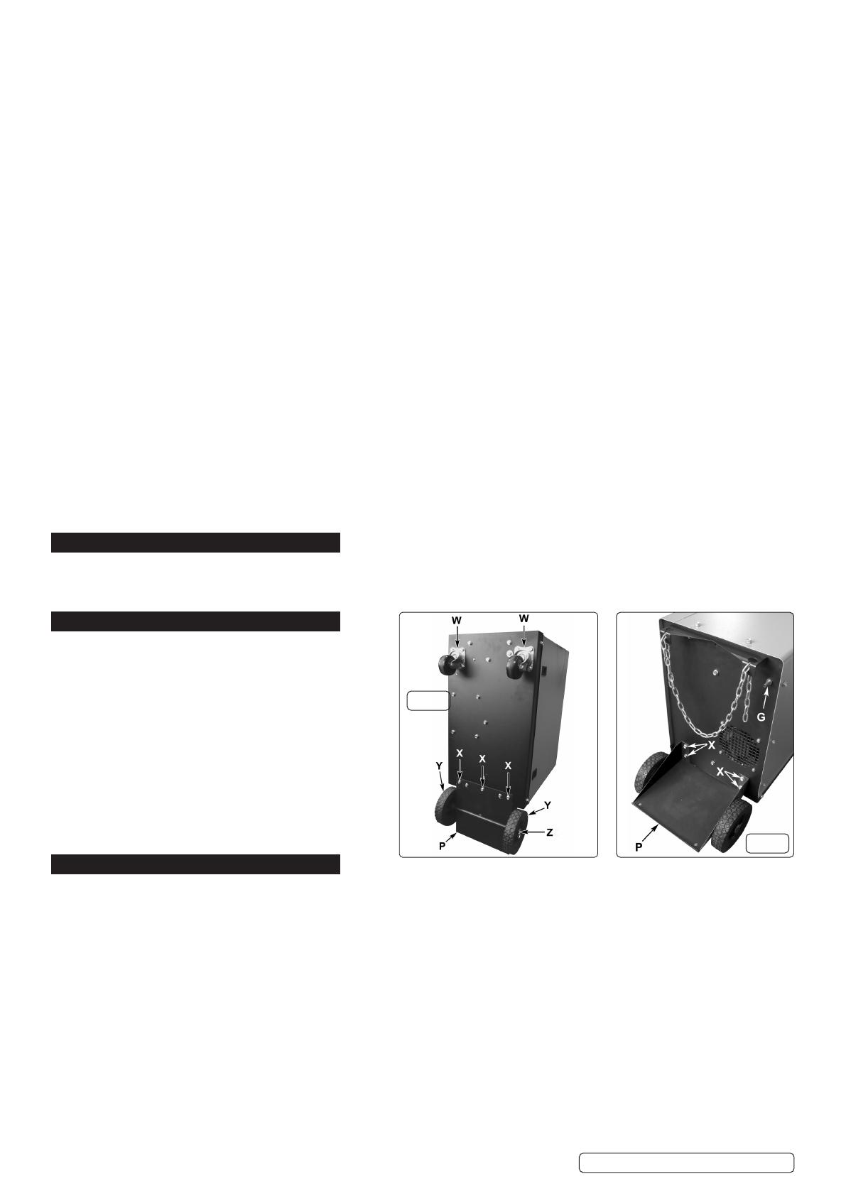
4.1. ASSEMBLING GAS PLATFORM: (Refer to ‘P’ in figs.1 & 2) Turn the welder upside down on a smooth non-abrasive surface. The
welder should be turned over by two people as it is very heavy.
4.1.1. The gas platform is held in place with 7 M6 x 10mm bolts requiring a 10mm spanner. The casing has pre-prepared threaded inserts ready
to take the fixings. Place the platform onto the base of the welder with the axle uppermost and fix in place with 3 bolts. See (X) in fig.1
below.
4.1.2. Insert the remaining four bolts through the two fixing flanges laying on the back of the welder. See (X) in fig.2. Finally, tighten all 7 bolts.
4.2. ASSEMBLING THE WHEELS: (Refer to fig.1)
4.2.1. Slide a wheel (Y) over each end of the solid axle attached to the gas platform. Slide a washer over each end of the axle and insert a split
pin (Z) through the hole in each end of the axle and bend it over to retain the wheels.
4.2.2. Bolt the two castors (W) to the front end of the base using the 8 bolts provided. The casing has pre-prepared threaded inserts ready to
take the fixings. See fig.1.
4.2.3. With the assistance of another person turn the welder the right way up onto its wheels.
4.2.4. The Gas Cylinder Bracket (Item 36) can be found stored inside the wire feed compartment, in the top corner above the wire feed
assembly. Remove from this location and fix to the rear of the machine.
4.3. ASSEMBLING THE EARTH CLAMP: (Refer to fig.3) Feed the eyelet on the end of the earth lead through the hole in the clamp arm as
shown in fig.3A.
4.4. Drop the eyelet over the terminal and firmly fix with the bolt provided as shown in fig.3B.
Original Language Version
© Jack Sealey Limited
fig.2
fig.1
SUPERMIG230.V2 Issue:1 08/07/22
4.5. INSTALLING THE GAS CYLINDER. The welder is designed to
accommodate small or medium sized gas cylinders up to a maximum
height of 1000mm. Contact your local Gas dealer for supply.
4.5.1. Place the gas cylinder onto the rear platform of the welder. See
fig.2-P.
4.5.2. Place one end of the fixing chain into one side of the retaining
bracket. Draw the chain around the cylinder and place it into the
slot on the other side of the bracket leaving as little slack in the chain as possible.
4.6. ATTACHING THE REGULATOR. Whichever gas you are using it is advisable to ‘crack’ the cylinder valve before attaching the regulator.
This means opening and closing the valve very quickly in order to blow away any dust and dirt that may have accumulated in the gas
outlet. Stand to one side whilst doing this.
4.6.1. CO² GAS. Ensure that the threads on the gas bottle are undamaged and free of oil and grease before attaching the regulator. (Oil or
grease in the presence of high pressure gases can be explosive). Ensure that the regulator has an undamaged gasket fitted. The
regulator will screw directly to the threads on the gas bottle. Tighten with a spanner.
4.6.2. ARGON GAS OR ARGON MIXTURES. Cylinders containing Argon gas and Argon mixtures have a female thread and will require the use
of a Bull Nose Adaptor to attach the regulator to the cylinder as indicated in fig.4. Ensure that the threads on the gas bottle are
undamaged and free of oil and grease before attaching the regulator. (Oil or grease in the presence of high pressure gases is explosive).
Fit the Bull Nose Adaptor to the cylinder first and tighten with a spanner. Ensure that the regulator has an undamaged gasket before
fitting onto the Bull Nose Adaptor. Tighten with a spanner.
4.6.3. Slide a clip over each end of the gas hose supplied. Push one end of the hose onto the regulator outlet and the other end over the gas
inlet spigot on the back of the welder. See fig.2G. Tighten the clips to ensure a good seal.
4.6.4. Close the regulator valve by turning it anti-clockwise before opening the cylinder valve. Stand to one side when opening the cylinder
valve.
4.6.5. Set the regulator flow rate to 5-8 litres/min depending on the material to be welded, and whether there are draughts which are
strong enough to disturb the gas flow.
4.7. CONNECT THE TORCH CABLE TO THE WELDER.
4.7.1. Align the pins on the Euro connector with the socket on the welder
front panel as shown in g.5. Push the connector into the socket
and rotate the locking ring (A) clockwise so that it draws the plug into
the socket as shown in g.6.
Note: damage to torches and cables is not covered by warranty.
4.8. FITTING A 15KG REEL OF WIRE
4.8.1. Ensure that the wire diameter used, is matched by the correct groove
size in the drive wheel and the correct tip size on the torch as well as
the correct torch liner. Failure to do this could cause the wire to slip
and/or bind.
4.8.2. Unscrew the locking knob from the end of the spool holder (see fig.7C)
and remove the spacer (B). The spacer is not required for
15kg reels of wire. Slide the reel of wire onto the spool holder and ensure that the clutch pin at the back of the spool holder (E)
engages into the guide hole in the wire reel moulding. This will prevent the wire reel from freewheeling on the spool holder. Ensure
that the wire is coming off the bottom of the reel in the direction of the wire drive unit as shown in fig.8 below.
4.9. FITTING A 5KG REEL OF WIRE
4.9.1. Ensure that the wire diameter used, is matched by the correct groove size in the drive wheel and the correct tip size on the torch as well
as the correct torch liner. Failure to do this could cause the wire to slip and/or bind.
4.9.2. Unscrew the locking knob from the end of the spool holder (see fig.7C) and remove the spacer. Slide the reel of wire onto the spool
holder and ensure that the clutch pin at the back of the spool holder (E) engages into the guide hole in the wire reel moulding.
This will prevent the wire reel from freewheeling on the spool holder. Slide the spacer onto the spool holder and retain it by screwing the
knob into place as shown above in fig.9. Ensure that the wire is coming off the bottom of the reel in the direction of the wire drive unit as
shown in fig.10.
fig.3
fig.9
fig.4
fig.7
fig.5
fig.8
fig.6
Original Language Version
© Jack Sealey Limited SUPERMIG230.V2 Issue:1 08/07/22
4.10. FEED WIRE THROUGH TO TORCH
4.10.1. Referring to fig.12 open the wire feed mechanism by pushing the locking/wire tension knob (1) down to the right allowing the pressure
roller carrier (2) to spring up revealing the feed roller. Ensure that the required feed groove (0.6 or 0.8) is in line with the wire path. See
Section 3.12 on how to reverse or change the roller.
4.10.2. Release the wire from the reel and cut off any bent portion ensuring that there are no burrs left on the end of the wire. Keep the wire under
tension at all times to prevent it uncoiling.
4.10.3. Straighten about 40-50mm of wire and gently push it through the flexible metal sheathed cable (3) and through the 6 or 8mm feed roller
groove and on into the torch cable liner.
4.10.4. Push down the pressure roller carrier onto the wire feed roller and hold it down. Lift up the locking/wire tension knob so that it enters the slot
in the pressure roller carrier and snaps into the indent in its top surface. See fig.13. Rotate the tension knob to a medium setting i.e. between
2 and 3.
4.10.5. 4.10.5. RRemove gas cup (fig.11-2) and contact tip (1) from end of torch as follows:emove gas cup (fig.11-2) and contact tip (1) from end of torch as follows:
a) Take torch in left hand with the torch tip facing to the right.
b) Grasp gas cup firmly in your right hand.
c) Turn gas cup clockwise only and pull it off end of torch tip.
WARNING! do not turn gas cup anti-clockwise, as this will damage the internal spring.
d) Unscrew copper contact tip (right hand thread) to remove.
4.10.6. 4.10.6. CCheck welder is switched off “0”, and that the earth clamp is away from the torch tip. Connect the welder to the mains power supply and heck welder is switched off “0”, and that the earth clamp is away from the torch tip. Connect the welder to the mains power supply and
set the voltage switch to one. set the voltage switch to one.
4.10.7. Set the wire speed knob to position 5 or 6. Keep the torch cable as straight as possible and press the torch switch. The wire will feed
through the torch.
4.10.8. When the wire has fed through, switch welder off, unplug from mains.
a) Take torch in left hand, slide the contact tip over the wire and screw back into place.
b) Grasp gas cup in right hand, push onto torch head and turn clockwise only. Do not turn gas cup anti-clockwise, as this will damage the
internal spring.
c) Cut wire so that it is just protruding from the cup.
4.11. SETTING WIRE TENSION
4.11.1. Adjust the wire tension by rotating the wire tension knob. Turn clockwise to increase the tension and anticlockwise to decrease the
tension. See (1) in fig13.
IMPORTANT: Too little or too much tension will cause problematic wire feed and result in poor welding.
4.11.2. Tension between rollers is checked by slowing down the wire between gloved fingers. If top feed roller skids the tension is correct. Use
as low a tension as possible, too high a tension will disfigure wire and result in a blown fuse.
4.12. CLUTCH ADJUSTMENT
Note: It is essential that the clutch is adjusted correctly.
4.12.1. 4.12.1. OOnce the wire is fed through the torch, switch on the machine and set the wire speed to maximum. nce the wire is fed through the torch, switch on the machine and set the wire speed to maximum.
4.12.2. 4.12.2. DDepress torch switch and release quickly. If the spool overruns it indicates that the clutch is too loose. epress torch switch and release quickly. If the spool overruns it indicates that the clutch is too loose.
4.12.3. 4.12.3. TTighten the clutch nut located in the centre of the wire spool holder with a spanner (fig.7-D) and test the machine as above until the wire ighten the clutch nut located in the centre of the wire spool holder with a spanner (fig.7-D) and test the machine as above until the wire
stops over running.
Note: DO NOT over tighten the clutch as this will cause wire feed problems and strain the motor.
4.13. 4.13. TTURNING/CHANGING THE DRIVE ROLLERURNING/CHANGING THE DRIVE ROLLER (See fig.14) (See fig.14)
4.13.1. Ensure that the wire diameter used, is matched by the correct groove size in the drive wheel and the correct tip size on the torch as well
as the correct torch liner. Failure to do this could cause the wire to slip and/or bind.
4.13.2. Referring to fig.12, open the wire feed mechanism by pushing the locking/wire tension knob (1) down to the right allowing the pressure
roller carrier (2) to spring up revealing the feed roller.
4.13.3. Referring to fig.14, loosen and unscrew the black feed roller retaining knob (C) and put to one side.
4.13.4. The roller carrier (A) is keyed to the main drive shaft and the drive roller (B) is keyed to the carrier, see below. Place a finger onto the
end of the drive shaft to prevent the carrier moving and slide the drive roller off the carrier with your other hand.
4.13.5. The size of each wire feed groove is printed on the edge of the roller on the same side as the groove.
4.13.6. Turn the roller over to use the other groove or use a roller with different sized grooves as required. The groove to be used should be
positioned furthest away from you to be in line with the drive path.
fig.12 fig.13 fig.14
Original Language Version
© Jack Sealey Limited
fig.10
fig.11
SUPERMIG230.V2 Issue:1 08/07/22
4.13.7. Check that the key in the carrier (A) is properly seated in its slot. Ensure that the slot on the inside face of the drive roller (B) is aligned
with the key and slide the roller back onto the carrier.
4.13.8. 4.13.8. SScrew the black roller retaining knob (C) back on to the end of the drive shaft and tighten. crew the black roller retaining knob (C) back on to the end of the drive shaft and tighten.
5. a MIG/MAG WELDING
5.13.1. A spool of welding wire is positioned on the welder’s spool holder and automatically
fed through an insulated liner in the torch to the tip. The torch assembly consists of a
switch, liner, gas hose, and control cable. The switch activates the wire feed roller and the gas flow.
Conversely, releasing the switch stops the wire feed and gas flow. The weld current is transferred to
the electrode (the wire) from the contact tip at the end of the torch. A gas cup fits over the contact tip
to direct the gas flow towards the weld ensuring that the arc welding process is shielded from oxidising air contaminates. The shielding
gas also assists heating of the weld materials. The torch is connected to the positive side of a DC rectifier, and the negative clamp is
attached to the workpiece.
IMPORTANT: Should you have no welding experience, we recommend you seek training from an expert source to ensure your
personal health & safety. Good Mig welding may be achieved only with continued, supervised practice.
5.1. PREPARATION FOR WELDING
IMPORTANT: BEFORE YOU COMMENCE, MAKE SURE THE MACHINE IS SWITCHED OFF AT THE MAINS. IF WELDING A CAR,
DISCONNECT THE BATTERY OR FIT AN ELECTRONIC CIRCUIT PROTECTOR. WE STRONGLY RECOMMEND THE USE
OF A Sealey “PROSAF/12V OR 24V IN ORDER TO PROTECT SOPHISTICATED ELECTRONICS. ENSURE YOU HAVE READ &
UNDERSTOOD THE ELECTRICAL SAFETY INSTRUCTIONS IN CHAPTER 1.
NOTE! When welding on a tilted plane ensure the welder is stable and is not in danger of falling over. Ensure the welder is sufficiently
secured.
5.1.1. Connecting the Earth Lead
To ensure a complete circuit, the earth lead must be securely attached to the work piece that is to be welded.
a) Best connection is obtained by grinding clean the point of contact on the workpiece before connecting the earth clamp.
b) The weld area must also be free of paint, rust, grease, etc.
c) When welding a vehicle, be sure the vehicle battery is disconnected or fit an Electronic Circuit Protector available from your Sealey
stockists.
5.1.2. Power Output switch
Set the switch to position 1 or 2 for welding up to 2mm thickness. Use settings 3,4,5,6. for thicker welds.
5.1.3. Setting the welder controls In principle, the lower the amperage required, the slower the wire speed. See setting chart below for
voltage and corresponding wire speeds. Note: these settings are only a guide and will vary according to the operator’s experience.
5.1.4. Welding mild steel
To weld mild steel you can use CO² gas for most tasks where spatter and the high build up of weld do not pose
a problem. Welding with a long arc reduces penetration and widens the arc. This in turn results
in more spatter. A long welding arc can be appropriate for welding butt joints in thin materials. Welding with a
short arc, at the same weld settings, results in greater penetration and a narrower weld and reduces the amount
of spatter. To achieve a consistent spatter free and flat weld, you must use an Argon/CO² mixture.
To weld aluminium use:
Argon gas,
0.8mm Contact Tip,
0.8mm Aluminium Wire,
5.1.5. Overload Protection
Thermostatic overload protection is provided. When an overload has
occurred, leave the unit to cool. The thermostat will automatically
reset the unit when the temperature has returned within limits.
5.1.6. Spot Welding
Spot welding may be carried out as shown in fig.16. It will be necessary
to fit a spot welding gas cup.
(a) Overlapping metal sheets with a maximum thickness of 0.8 mm may be
welded as indicated.
(b) Alternatively they may be welded edge to surface as indicated.
(c) For thicker sheet pre drilled holes holes may be employed.
5.1.7. Use the wire feed control in conjunction with the spot weld timer beside it.
To activate the timer turn the knob clockwise. The settings
indicated in the black portion of the chart are for guidance only and may vary
with operator’s experience.
5.2.
5.3.
Wire 0.6mm Steel
Argon / CO² Mix
Voltage
Step: 1 2 3 4 5 6
Wire
Speed: 5 6 7 8 9 10
SETTINGS SHOWN
AS GUIDE ONLY
fig.15
fig.16
Original Language Version
© Jack Sealey Limited SUPERMIG230.V2 Issue:1 08/07/22
6. a RATINGS PLATE
On the front of the welder is the ratings plate, giving the
following data:
1 - The standard relating to the safety and construction
of arc welding and associated equipment.
2 - Single phase transformer - rectifier.
3 - Welding with a continuous flow of welding wire.
4 - Single-phase AC supply.
5 - Rating of internal protection provided by casing.
6 - Output
U0: Rated minimum & maximum no load voltage.
I2, U2: Current and corresponding voltage.
X: Welding ratio based on a 10 minute cycle. 20% indicates 2 minutes welding and 8 minutes rest, 100% indicates continuous welding.
7 - Mains Supply U1: Rated supply voltage and frequency. Imax: Maximum current. I1eff: Maximum effective current.
8 - Welding current range.
9 - Serial Number. Specifically identifies each welder.
7. a MAINTENANCE
7.1. WIRE FEED UNIT
Check the wire feed unit at regular intervals. The feed roller wire guide plays an important part in obtaining consistent results. Poor
wire feed affects welding. Clean the rollers weekly, especially the feed roller groove, removing all dust deposits.
7.2. TORCH
Protect the torch cable assembly from mechanical wear. Clean the liner from the machine forwards by using compressed air. If the liner is
clogged it must be replaced.
7.3. CHANGING FEED ROLLER
(See Section 3.12)
7.4. CONTACT TIP
The contact tip is a consumable item and must be replaced when the hole becomes enlarged or oval. The contact tip MUST be kept free
from spatter to ensure an unimpeded flow of gas. Refer to fig.11 and section 3.9 for removal and replacement.
7.5. GAS CUP
The gas cup must also be kept clean and free from spatter. Build up of spatter inside the gas cup can cause a short circuit at the contact
tip which will result in either the fuse blowing on the printed circuit card, or expensive machine repairs. To keep the contact tip free from
spatter, we recommend the use of Sealey anti-spatter spray (MIG/722308) available from your Sealey stockist. Refer to fig.12 and section
3.9 for removal and replacement.
7.6. REPLACING THE LINER
Wind the wire back on to the spool and secure it. Unscrew the torch from the machine and undo the brass nut. The liner should
now be visible. Pull it out and replace with a new one.
8. ttTROUBLESHOOTINGroubleshooting
Original Language Version
© Jack Sealey Limited
PROBLEM POSSIBLE CAUSE REMEDY
1. Power source stops Overheating protection activated due to overload Protection automatically resets when transformer has cooled (about 15 min)
2. No weld current Rectifier blown Replace rectifier
3. No weld current Bad connection between clamp & workpiece Clean or grind contact surface and weld area
Break in earth lead Repair or replace earth lead.
Break in torch lead Repair or replace torch
4. Feed motor not working, lamp is on Gear damaged or worn Replace gears. (Contact service agent)
Motor defective Replace motor (Contact service agent)
5. Wire does not feed, feed roller rotates Pressure roller improperly adjusted Adjust tension
Dirt, copper, dust, etc, has collected in torch liner Clean the liner from the machine forward. Use compressed air. If too much dirt,
replace the liner.
Gas cup (Nozzle) or tip defective Replace gas cup (nozzle) and/or tip. (Section 3.9.4 to 3.9.7)
Deformed wire Check roller tension and adjust it if necessary (Section 3.10)
6. Wire feeds unevenly Dirt, etc, in liner Clean the liner from the machine forward. Use compressed air
Gas cup (Nozzle) or Tip defective Replace gas cup (nozzle) and/or tip. (Section 3.9.4 to 3.9.7)
Gas cup (Nozzle) spattered Clean or replace gas cup (nozzle) (Section 3.9.4 to 3.9.7)
Feed roller groove clogged Clean feed roller. (Section 3.12).
Feed roller groove deformed Replace feed roller. (Section 3.12)
Pressure roller tension improper Adjust tension. (Section 3.10)
7. Unstable arc Incorrect settings Check settings. (Section 4)
Impurities in weld area Clean and/or grind workpiece. (Section 4.1.1)
Worn or defective gas cup (nozzle) Replace gas cup (nozzle). (Section 3.9.4 to 3.9.7)
SUPERMIG230.V2 Issue:1 08/07/22
Sealey Group, Kempson Way, Suffolk Business Park, Bury St Edmunds, Suffolk. IP32 7AR
01284 757500 01284 703534 sales@sealey.co.uk www.sealey.co.uk
ENVIRONMENT PROTECTION
Recycle unwanted materials instead of disposing of them as waste. All tools, accessories and packaging should be sorted, taken to
a recycling centre and disposed of in a manner which is compatible with the environment. When the product becomes completely
unserviceable and requires disposal, drain any fluids (if applicable) into approved containers and dispose of the product and fluids
according to local regulations.
WEEE REGULATIONS
Dispose of this product at the end of its working life in compliance with the EU Directive on Waste Electrical and Electronic Equipment
(WEEE). When the product is no longer required, it must be disposed of in an environmentally protective way. Contact your local solid
waste authority for recycling information.
REGISTER YOUR
PURCHASE HERE
Original Language Version
© Jack Sealey Limited
8. Porous weld No gas Open gas cylinder, regulate gas flow
Gas cup clogged Clean or replace cup. (nozzle) (Section 3.9.4 to 3.9.7)
Draft blowing away shielding gas Screen off welding site or increase gas flow
Rusty or dirty joints Clean and/or grind workpiece. (Section 4.1.1)
Torch too far from or at wrong angle to work The distance from gas cup to workpiece should be 8 to 10mm
Gas leak Check hoses, connections and torch assembly. (Section 3.5). Press the gas cup in
correction position
Faulty Electrovalve Clean out or replace
9. Electrode sticking in gas cup (nozzle) Worn or defective gas cup (nozzle) Replace gas cup (nozzle). (Section 3.9.4 to 3.9.7)
Electrode deformed Check roller tension. (Section 3.10)
Wire speed too slow See recommendations for wire speed
10. Irregular weld bead Torch incorrectly held Use correct torch angle
Wire weaving in weld pool Check roller tension and adjust as needed. (Section 3.10)
11. Weld bead too narrow and raised Weld current too low Increase power and wire speed. (Section 4)
Weld speed too high Move torch slower and weave a little more
12. Weld bead too wide Weld current too high Decrease power and wire speed. (Section 4)
Weld speed too low Move torch faster and weave less
Arc too long Bring torch closer to workpiece
13. Poor penetration Weld current too low Increase power and wire speed. (Section 4)
Arc too long Bring torch closer to workpiece
14. Excessive penetration Weld current too high Decrease power and wire speed. (Section 4)
Weld speed too slow Move torch faster
incorrect distance of torch to workpiece Torch distance should be 8-10mm
SUPERMIG230.V2 Issue:1 08/07/22
Note: It is our policy to continually improve products and as such we reserve the right to alter data, specifications and component
parts without prior notice. Please note that other versions of this product are available. If you require documentation for alternative
versions, please email or call our technical team on technical@sealey.co.uk or 01284 757505.
Important: No Liability is accepted for incorrect use of this product.
Warranty: Guarantee is 12 months from purchase date, proof of which is required for any claim.
  • Page 1 1
  • Page 2 2
  • Page 3 3
  • Page 4 4
  • Page 5 5
  • Page 6 6
  • Page 7 7

Sealey SUPERMIG230.V2 Operating instructions

Category
Welding System
Type
Operating instructions

Sealey SUPERMIG230.V2 is a professional MIG welder with a Binzel® Euro torch, capable of welding stainless steel and aluminum. It offers excellent continuous performance on car panel thickness material, thanks to its forced air cooling system, which provides a high duty cycle. The Binzel® non-live Euro torch reduces accidental arcing and ensures a steadier weld bead, making it comfortable to use. The welder comes with an industrial gas regulator and contact tips of 0.6mm and 0.8mm, as well as a gas cup.

Ask a question and I''ll find the answer in the document

Finding information in a document is now easier with AI