Banner R45C User manual

Type
User manual

Banner R45C is a compact converter that reads sensor distance over RSD communications and outputs a voltage or current analog value. Its rugged design meets IP65, IP67, and IP68 standards, making it suitable for harsh industrial environments. The device features two amber LED indicators for connected sensor status and a green LED indicator for power status. It supports various Q5XKLAF5000-Q8 and Q5XKLAF2000-Q8 sensor versions and offers analog voltage range of 0 V to 10 V and analog current range of 4 mA to 20 mA. The R45C provides easy installation with a 4.

Banner R45C is a compact converter that reads sensor distance over RSD communications and outputs a voltage or current analog value. Its rugged design meets IP65, IP67, and IP68 standards, making it suitable for harsh industrial environments. The device features two amber LED indicators for connected sensor status and a green LED indicator for power status. It supports various Q5XKLAF5000-Q8 and Q5XKLAF2000-Q8 sensor versions and offers analog voltage range of 0 V to 10 V and analog current range of 4 mA to 20 mA. The R45C provides easy installation with a 4.

Instruction Manual
Compact converter that reads sensor distance over RSD communications
and outputs a voltage or current analog value
Rugged over-molded design meets IP65, IP67, and IP68
Connects directly to a sensor or anywhere in-line for ease of use
Models
Housing
R45
C = Converter Q = Integral M12 quick disconnect
Q
Connector
Female
I = Analog Current Out
U = Analog Voltage Out
Male
C I
RSDW
Function
--
RSDW = Converter communicates over
Pin 2 (White Wire) using the RSD
communications protocol
RSDG = Converter communicates over
Pin 5 (Gray Wire) using the RSD
communications protocol
The R45C-RSDW-xx converter models are compatible with the following sensors:
Sensor Versions
Q5XKLAF5000-Q8 V3.0 build and later
Q5XKLAF2000-Q8 V4.0 build and later
The R45C-RSDG-xx converter models are compatible with the following sensors:
Sensor Versions Connection
Q5XKLAF5000-Q8 V3.0 build and later MQDC-4501SS crossover cable required
Q5XKLAF2000-Q8 V4.0 build and later
Overview
The R45C RSD to Analog Output Converter connects to a distance sensor, and over the RSD communications link, receives the
sensor's calculated distance. That distance is converted to an analog value for host side consumption.
Voltage range is 0 V to 10 V
Current range is 4 mA to 20 mA
R45C RSD to Analog Output Converter
Original Document
222331 Rev. B
14 December 2022
222331
Status Indicators
The R45C RSD to Analog Output Converter has two amber LED indicators on both sides for connected sensor status and provides
adequate indication visibility. There is also a green LED indicator on both sides of the converter, which signals the device's power
status.
Figure 1. R45C status indicators – front and back
Status LED 2
(on either side)*
* Indicator LEDs are visible through translucent housing
Rotate 180˚
Power LED
(on either side)*
Status LED 1
(on either side)*
Status 1 LED – Amber
Indication Status
Solid On/Off Follows status of LED 1 of connected
sensor
Flash at 1 Hz rate Powered on, no sensor connected
Flash at 4 Hz rate, alternating with
Status 2 LED
Powered on, sensor connected, but
sensor is not RSD capable
Status 2 LED – Amber
Indication Status
Solid On/Off Follows status of LED 2 of connected
sensor
Flash at 1 Hz rate Powered on, no sensor connected
Flash at 4 Hz rate, alternating with
Status 1 LED
Powered on, sensor connected, but
sensor is not RSD capable
Installation
Mechanical Installation
Install the R45C to allow access for functional checks, maintenance, and service or replacement. Do not install the R45C in such a
way to allow for intentional defeat.
All mounting hardware is supplied by the user. Fasteners must be of sufficient strength to guard against breakage. Use of permanent
fasteners or locking hardware is recommended to prevent the loosening or displacement of the device. The mounting hole (4.5 mm)
in the R45C accepts M4 (#8) hardware. See the figure below to help in determining the minimum screw length.
12.9 mm
NUT
3.9 mm
3 mm * for minimum
engagement of
three threads
Screw Length (with screw head fitting in counterbore) = 12.9 mm + “X” mm + 3 mm
X
*
CAUTION: Do not overtighten the R45C's mounting screw during installation. Overtightening can affect the
performance of the R45C.
R45C RSD to Analog Output Converter
2 www.bannerengineering.com - Tel: + 1 888 373 6767 P/N 222331 Rev. B
Connection Options
When connecting the R45C to a sensor or control system, an adapter may be required depending on the sensor.
For the R45C-RSDG-xx, Pin 5 (gray wire) is used to communicate with an attached sensor.
For the R45C-RSDW-xx, Pin 2 (white wire) is used to communicate with an attached sensor.
Wiring
The following wiring diagrams are examples of different R45C outputs. Wiring is dependent on the sensor connected to the R45C.
Analog (Current)
shield
+
12-30V dc
A_Out
Banner 1-wire
4-20 mA
3
1
2
4
5
Analog (Voltage)
shield
+
12-30V dc
A_Out
Banner 1-wire
3
1
2
4
5
0-10V
Female Male Pin Wire Color
1
4
5
3
2
2
3
4
1
5
1 Brown
2 White
3 Blue
4 Black
5 Gray
Female (RSDG) Signal Description
Pin 1 18 V DC to 30 V DC
Pin 2 No Connection (N/C)
Pin 3 Ground
Pin 4 Pass-through to Pin 4 (Male)
Pin 5 Banner RSD communications
Female (RSDW) Signal Description
Pin 1 18 V DC to 30 V DC
Pin 2 Banner RSD communications
Pin 3 Ground
Pin 4 Pass-through to Pin 4 (Male)
Pin 5 No Connection (N/C)
Male (Analog Output) Signal Description
Pin 1 18 V DC to 30 V DC
Pin 2 Analog Out
Pin 3 Ground
Pin 4 Pass-through to Pin 4 (Female)
Pin 5 Banner 1-wire
R45C RSD to Analog Output Converter
P/N 222331 Rev. B www.bannerengineering.com - Tel: + 1 888 373 6767 3
Specifications
Supply Voltage
18 V DC to 30 V DC at 50 mA maximum
Supply Protection Circuitry
Protected against reverse polarity and transient voltages
Leakage Current Immunity
400 µA
Resolution
14 bits
Accuracy
0.5%
Indicators
Green: Power LED
Amber: Status 1 LED
Amber: Status 2 LED
Connections
Integral male/female 5-pin M12 quick disconnect
Construction
Coupling Material: Nickel-plated brass
Connector Body: PVC translucent black
Vibration and Mechanical Shock
Meets IEC 60068-2-6 requirements (Vibration: 10 Hz to 55 Hz, 0.5 mm
amplitude, 5 minutes sweep, 30 minutes dwell)
Meets IEC 60068-2-27 requirements (Shock: 15G 11 ms duration, half sine
wave)
Certifications
Banner Engineering Europe
Park Lane, Culliganlaan 2F bus
3, 1831 Diegem, BELGIUM
Turck Banner LTD Blenheim
House, Blenheim Court,
Wickford, Essex SS11 8YT,
Great Britain
Environmental Rating
IP65, IP67, IP68
NEMA/UL Type 1
Operating Conditions
Temperature: –40 °C to +70 °C (–40 °F to +158 °F)
90% at +70 °C maximum relative humidity (non-condensing)
Storage Temperature: –40 °C to +80 °C (–40 °F to +176 °F)
Required Overcurrent Protection
WARNING: Electrical connections must be
made by qualified personnel in accordance with
local and national electrical codes and
regulations.
Overcurrent protection is required to be provided by end product application
per the supplied table.
Overcurrent protection may be provided with external fusing or via Current
Limiting, Class 2 Power Supply.
Supply wiring leads < 24 AWG shall not be spliced.
For additional product support, go to www.bannerengineering.com.
Supply Wiring (AWG) Required Overcurrent Protection (Amps)
20 5.0
22 3.0
24 2.0
26 1.0
28 0.8
30 0.5
Dimensions
All measurements are listed in millimeters [inches], unless noted otherwise.
Accessories
Cordsets
The following cordsets can be used to connect the R45C-RSDG-xx to a 4-pin sensor where the white wire (pin 2) is used for
communication (for example, Q5XLAF5000 and Q5XLAF2000 sensors).
R45C RSD to Analog Output Converter
4 www.bannerengineering.com - Tel: + 1 888 373 6767 P/N 222331 Rev. B
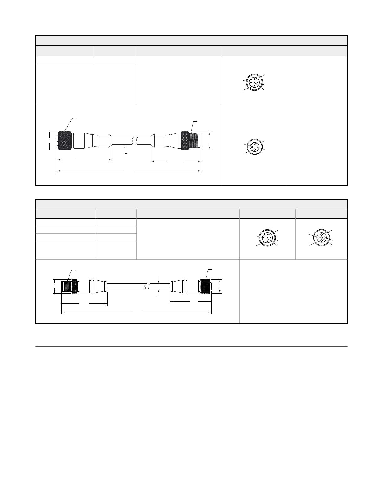
4-Pin Female and 5-Pin Male Threaded M12 Cordset—Double Ended
Model Length "L1" Style Pinout
MQDC-4501SS 0.30 m (0.98 ft)
Female Straight/ Male Straight
Male
1
4
5
3
2
1 = Brown
2 = Not Used
3 = Blue
4 = Black
5 = White
MQDC-4506SS 1.83 m (6.00 ft)
M12 X 1.0
43.5 ± 0.5
“L1”
ø 5.9
M12 X 1.0
ø 14.5 ø 14.5
40 ± 0.5
Female
1 = Brown
2 = White
3 = Blue
4 = Black
The following cordsets can be used to extend the distance between the sensor and the R45C-RSDG-xx or R45C-RSDW-xx.
5-Pin Male Threaded and 5-Pin Female Quick Disconnect M12 Cordset with Shield—Double Ended
Model Length "L1" Style Pinout (Male) Pinout (Female)
MQDEC3-503SS 0.91 m (2.99 ft)
Female Straight/Male Straight
1
4
5
3
2
2
3
4
1
5
MQDEC3-506SS 1.83 m (6 ft)
MQDEC3-515SS 4.58 m (15 ft)
MQDEC3-530SS 9.2 m (30.2 ft)
M12 x 1
14.5
ø 5.9
14.5
“L1”
47.4 47.4
M12 x 1
1 = Brown
2 = White
3 = Blue
4 = Black
5 = Gray
Banner Engineering Corp. Limited Warranty
Banner Engineering Corp. warrants its products to be free from defects in material and workmanship for one year following the date of shipment. Banner Engineering Corp. will repair or
replace, free of charge, any product of its manufacture which, at the time it is returned to the factory, is found to have been defective during the warranty period. This warranty does not
cover damage or liability for misuse, abuse, or the improper application or installation of the Banner product.
THIS LIMITED WARRANTY IS EXCLUSIVE AND IN LIEU OF ALL OTHER WARRANTIES WHETHER EXPRESS OR IMPLIED (INCLUDING, WITHOUT LIMITATION, ANY
WARRANTY OF MERCHANTABILITY OR FITNESS FOR A PARTICULAR PURPOSE), AND WHETHER ARISING UNDER COURSE OF PERFORMANCE, COURSE OF DEALING OR
TRADE USAGE.
This Warranty is exclusive and limited to repair or, at the discretion of Banner Engineering Corp., replacement. IN NO EVENT SHALL BANNER ENGINEERING CORP. BE LIABLE TO
BUYER OR ANY OTHER PERSON OR ENTITY FOR ANY EXTRA COSTS, EXPENSES, LOSSES, LOSS OF PROFITS, OR ANY INCIDENTAL, CONSEQUENTIAL OR SPECIAL
DAMAGES RESULTING FROM ANY PRODUCT DEFECT OR FROM THE USE OR INABILITY TO USE THE PRODUCT, WHETHER ARISING IN CONTRACT OR WARRANTY,
STATUTE, TORT, STRICT LIABILITY, NEGLIGENCE, OR OTHERWISE.
Banner Engineering Corp. reserves the right to change, modify or improve the design of the product without assuming any obligations or liabilities relating to any product previously
manufactured by Banner Engineering Corp. Any misuse, abuse, or improper application or installation of this product or use of the product for personal protection applications when the
product is identified as not intended for such purposes will void the product warranty. Any modifications to this product without prior express approval by Banner Engineering Corp will void
the product warranties. All specifications published in this document are subject to change; Banner reserves the right to modify product specifications or update documentation at any time.
Specifications and product information in English supersede that which is provided in any other language. For the most recent version of any documentation, refer to:
www.bannerengineering.com.
For patent information, see www.bannerengineering.com/patents.
R45C RSD to Analog Output Converter
P/N 222331 Rev. B www.bannerengineering.com - Tel: + 1 888 373 6767 5
FCC Part 15
This device complies with Part 15 of the FCC Rules. This equipment generates, uses, and can radiate radio frequency energy and, if
not installed and used in accordance with the instruction manual, may cause harmful interference to radio communications.
Operation is subject to the following two conditions: 1) This device may not cause harmful interference; and 2) This device must
accept any interference received, including interference that may cause undesired operation.
Industry Canada
This device complies with CAN ICES-3 (B)/NMB-3(B). Operation is subject to the following two conditions: 1) This device may not
cause harmful interference; and 2) This device must accept any interference received, including interference that may cause
undesired operation.
Cet appareil est conforme à la norme NMB-3(B). Le fonctionnement est soumis aux deux conditions suivantes : (1) ce dispositif ne
peut pas occasionner d'interférences, et (2) il doit tolérer toute interférence, y compris celles susceptibles de provoquer un
fonctionnement non souhaité du dispositif.
R45C RSD to Analog Output Converter
© Banner Engineering Corp. All rights reserved
  • Page 1 1
  • Page 2 2
  • Page 3 3
  • Page 4 4
  • Page 5 5
  • Page 6 6

Banner R45C User manual

Type
User manual

Banner R45C is a compact converter that reads sensor distance over RSD communications and outputs a voltage or current analog value. Its rugged design meets IP65, IP67, and IP68 standards, making it suitable for harsh industrial environments. The device features two amber LED indicators for connected sensor status and a green LED indicator for power status. It supports various Q5XKLAF5000-Q8 and Q5XKLAF2000-Q8 sensor versions and offers analog voltage range of 0 V to 10 V and analog current range of 4 mA to 20 mA. The R45C provides easy installation with a 4.

Ask a question and I''ll find the answer in the document

Finding information in a document is now easier with AI