EuroLite LED T1000 User manual
- Category
- Stroboscopes & disco lights
- Type
- User manual
This manual is also suitable for

©
Copyright
Nachdruck verboten!
Reproduction prohibited!
Réproduction interdit!
Prohibida toda reproducción.
Für weiteren Gebrauch aufbewahren!
Keep this manual for future needs!
Gardez ce mode d’emploi pour des
utilisations ultérieures!
Guarde este manual para posteriores usos.
BEDIENUNGSANLEITUNG
USER MANUAL
MODE D'EMPLOI
MANUAL DEL USUARIO
LED T500 / T1000
RGB Color Changer

00028142.DOC, Version 1.0
2/35
MULTI-LANGUAGE-INSTRUCTIONS
Inhaltsverzeichnis
Table of contents
Sommaire
Contenido
EINFÜHRUNG................................................................................................................................................... 4
Features ......................................................................................................................................................... 4
SICHERHEITSHINWEISE................................................................................................................................. 4
BESTIMMUNGSGEMÄßE VERWENDUNG..................................................................................................... 6
INSTALLATION ................................................................................................................................................ 7
Befestigung .................................................................................................................................................... 7
Anschluss an den DMX-512 Controller / Verbindung Gerät – Gerät ............................................................. 7
Master/Slave-Betrieb...................................................................................................................................... 8
Anschluss ans Netz........................................................................................................................................ 8
BEDIENUNG ..................................................................................................................................................... 9
Steuerung über FERNBEDIENUNG .............................................................................................................. 9
DMX-gesteuerter Betrieb ............................................................................................................................... 9
DMX-Protokoll .............................................................................................................................................. 10
Einlegen/Wechseln der Batterie................................................................................................................... 10
REINIGUNG UND WARTUNG........................................................................................................................ 11
TECHNISCHE DATEN .................................................................................................................................... 11
INTRODUCTION ............................................................................................................................................. 12
Features ....................................................................................................................................................... 12
SAFETY INSTRUCTIONS............................................................................................................................... 12
OPERATING DETERMINATIONS.................................................................................................................. 13
INSTALLATION .............................................................................................................................................. 15
Attachment ................................................................................................................................................... 15
DMX-512 connection / connection between fixtures.................................................................................... 15
Master/Slave-Operation ............................................................................................................................... 16
Connection with the mains........................................................................................................................... 16
OPERATION.................................................................................................................................................... 17
Operation via IR REMOTE CONTROL........................................................................................................ 17
DMX-controlled operation ............................................................................................................................ 17
DMX-protocol ............................................................................................................................................... 18
Inserting/Replacing the battery .................................................................................................................... 18
CLEANING AND MAINTENANCE ................................................................................................................. 18
TECHNICAL SPECIFICATIONS..................................................................................................................... 19
Page is loading ...
Page is loading ...
Page is loading ...
Page is loading ...
Page is loading ...
Page is loading ...
Page is loading ...
Page is loading ...
Page is loading ...

00028142.DOC, Version 1.0
12/35
USER MANUAL
LED RGB T500 / T1000 Color Changer
For your own safety, please read this user manual carefully before you initially start-up.
Every person involved with the installation, operation and maintenance of this device has to
- be qualified
- follow the instructions of this manual
- consider this manual to be part of the total product
- keep this manual for the entire service life of the product
- pass this manual on to every further owner or user of the product
- download the latest version of the user manual from the Internet
INTRODUCTION
Thank you for having chosen a EUROLITE LED RGB Color Changer. If you follow the instructions given in
this manual, we are sure that you will enjoy this device for a long period of time.
Unpack your LED RGB Color Changer.
Features
Brilliant High Power LED RGB Outdoor Color Changer!
Control via optional IR remote or any regular 512-DMX-controller • Functions: static colors, automatic color
change, internal programs, strobe effect, Master/Slave • Ideal LED-luminary for outdoor use • Fixed
installation is recommended • Locking possibility at the mounting bracket • Perfect in public places and in
front of buildings • The weather-resistant housing also allows operation during bad weather • Extremely
compact housing in an appealing design • Ready for connection with power cord and safety power plug •
Available in 2 sizes • Available in 20° or in 40° versions of the LED beam angle • Advantages of High-Power
LED-technology: extreme light output, extremely long life, low power consumption, defacto maintenance free
SAFETY INSTRUCTIONS
CAUTION!
Becarefulwithyouroperations.Withadangerousvoltageyoucansufferadangerous
electricshockwhentouchingthewires!
This device has left our premises in absolutely perfect condition. In order to maintain this condition and to
ensure a safe operation, it is absolutely necessary for the user to follow the safety instructions and warning
notes written in this user manual.
Important:
Damages caused by the disregard of this user manual are not subject to warranty. The dealer
will not accept liability for any resulting defects or problems.

00028142.DOC, Version 1.0
13/35
If the device has been exposed to drastic temperature fluctuation (e.g. after transportation), do not switch it
o
n immediately. The arising condensation water might damage your device. Leave the device switched off
until it has reached room temperature.
Please make sure that there are no obvious transport damages. Should you notice any damages on the A/C
connection cable or on the casing, do not take the device into operation and immediately consult your local
dealer.
This device falls under protection-class I. The power plug must only be plugged into a protection class I
outlet. The voltage and frequency must exactly be the same as stated on the device. Wrong voltages or
power outlets can lead to the destruction of the device and to mortal electrical shock.
Always plug in the power plug last. The power plug must always be inserted without force. Make sure that
the plug is tightly connected with the outlet.
Never let the power-cord come into contact with other cables! Handle the power-cord and all connections
with the mains with particular caution! Never touch them with wet hands, as this could lead to mortal
electrical shock.
Never modify, bend, strain mechanically, put pressure on, pull or heat up the power cord. Never operate next
to sources of heat or cold. Disregard can lead to power cord damages, fire or mortal electrical shock.
The cable insert or the female part in the device must never be strained. There must always be sufficient
cable to the device. Otherwise, the cable may be damaged which may lead to mortal damage.
Make sure that the power-cord is never crimped or damaged by sharp edges. Check the device and the
power-cord from time to time.
If extension cords are used, make sure that the core diameter is sufficient for the required power
consumption of the device. All warnings concerning the power cords are also valid for possible extension
cords.
Always disconnect from the mains, when the device is not in use or before cleaning it. Only handle the
power-cord by the plug. Never pull out the plug by tugging the power-cord. Otherwise, the cable or plug can
be damaged leading to mortal electrical shock. If the power plug or the power switch is not accessible, the
device must be disconnected via the mains.
If the power plug or the device is dusty, the device must be taken out of operation, disconnected and then be
cleaned with a dry cloth. Dust can reduce the insulation which may lead to mortal electrical shock. More
severe dirt in and at the device should only be removed by a specialist.
There must never be any objects entering into the device. This is especially valid for metal parts. If any metal
parts like staples or coarse metal chips enter into the device, the device must be taken out of operation and
disconnected immediately. Malfunction or short-circuits caused by metal parts may cause mortal injuries.
HEALTHHAZARD!
Neverlookdirectlyintothelightsource,assensitivepersonsmaysufferan
epilepticshock(especiallymeantforepileptics)!
Keep away children and amateurs!
Never leave this device running unattended.
OPERATING DETERMINATIONS
This device is an architectural light for creating decorative effects. This product is only allowed to be
operated with an alternating current of 230 V, 50 Hz.

00028142.DOC, Version 1.0
14/35
This device is jet-proof (IP 65) and therefore qualified for indoor and outdoor use. In order to maintain this
p
rotection grade after opening the housing, all rubber sealings must be examined for damages and always
be correctly installed.
This device is designed for professional use, e.g. on stages, in discotheques, theatres etc.
Lighting effects are not designed for permanent operation. Consistent operation breaks will ensure that the
d
evice will serve you for a long time without defects.
Do not shake the device. Avoid brute force when installing or operating the device.
When choosing the installation-spot, there should not be any cables lying around. You endanger your own
and the safety of others!
The ambient temperature must always be between -25° C and +45° C. Keep away from direct insulation
(particularly in cars) and heaters.
The maximum relative humidity is 100 % with an ambient temperature of 25° C.
This device must only be operated in an altitude between -20 and 2000 m over NN.
Never use the device during thunderstorms. Over voltage could destroy the device. Always disconnect the
device during thunderstorms.
When choosing the installation-spot, please make sure that the device is not exposed to extreme heat,
moisture or dust. There should not be any cables lying around. You endanger your own and the safety of
others!
The symbol
---m
determines the minimum distance from lighted objects. The minimum distance
between light-output and the illuminated surface must be more than 0.1 meters.
This device is only allowed for an installation via the mounting brackets. In order to safeguard sufficient
ventilation, leave 50 cm of free space around the device.
The housing must never touch surrounding surfaces or objects.
Make sure that the area below the installation place is blocked when rigging, derigging or servicing the
fixture.
Only operate the fixture after having checked that the housing is firmly closed and all screws are tightly
fastened.
The maximum ambient temperature T
a
= 45° C must never be exceeded.
Operate the device only after having become familiarized with its functions. Do not permit operation by
persons not qualified for operating the device. Most damages are the result of unprofessional operation!
Never use solvents or aggressive detergents in order to clean the device! Rather use a soft and damp cloth.
Please use the original packaging if the device is to be transported. Make sure that you pack the device in
the original state.
Please consider that unauthorized modifications on the device are forbidden due to safety reasons!
If this device will be operated in any way different to the one described in this manual, the product may suffer
damages and the guarantee becomes void. Furthermore, any other operation may lead to dangers like short-
circuit, burns, electric shock, lamp explosion, crash etc.

00028142.DOC, Version 1.0
15/35
INSTALLATION
Permanent installation is recommended!
Attachment
Before attaching the device, make sure that the installation area can hold a minimum point load of 10 times
the device's weight.
T
he device must only be installed absolutely planar at a vibration-free, oscillation-free and fire-resistant
location. Make sure that the device is installed absolutely planar by using a water-level.
The device must be installed out of the reach of people.
The device must always be installed via all fixation holes. Do only use appropriate screws and make sure
that the screws are properly connected with the ground.
The durability of the installation depends very much on the material used at the installation area (building
material) such as wood, concrete, gas concrete, brick etc. This is why the fixing material must be chosen to
suit the wall material. Always ask a specialist for the correct plug/screw combination indicating the maximum
load and the building material.
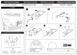
Procedure:
Step 1: On the mounting brackets of the device, there are the holes for the installation.
Step 2: Hold the mounting brackets with the device onto the location where it is to be installed.
Step 3: Mark the boreholes with a pen or a suitable tool.
Step 4: Drill the holes.
Step 5: Hold the mounting brackets in the desired position and tighten them.
Adjust the desired inclination-angle via the mounting brackets and tighten the fixation screws.
DANGERTOLIFE!
Beforetakingintooperationforthefirsttime,theinstallationhastobeapprovedbyanexpert!
Attention: After mounting the luminaries in the desired location, be sure to tighten the screw on the
underside of the mounting brackets with an imbus key. This prevents a possible slipping of the device.
DMX-512 connection / connection between fixtures
The wires must not come into contact with each other, otherwise
the fixtures will not work at all, or will not work properly.
Please note, the starting address depends upon which controller is being used.

00028142.DOC, Version 1.0
16/35
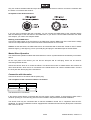
Only use a stereo shielded cable and 3-pin XLR-plugs and connectors in order to connect the controller with
t
he fixture or one fixture with another.
Occupation of the XLR-connection:
If you are using controllers with this occupation, you can connect the DMX-output of the controller directly
with the DMX-input of the first fixture in the DMX-chain. If you wish to connect DMX-controllers with other
XLR-outputs, you need to use adapter-cables.
Building a serial DMX-chain:
Connect the DMX-output of the first fixture in the DMX-chain with the DMX-input of the next fixture. Always
connect one output with the input of the next fixture until all fixtures are connected.
Caution: At the last fixture, the DMX-cable has to be terminated with a terminator. Solder a 120
resistor
between Signal (–) and Signal (+) into a 3-pin XLR-plug and plug it in the DMX-output of the last fixture.
Master/Slave-Operation
The master/slave-operation enables that several devices can be synchronized and controlled by one master-
device.
On the rear panel of the device you can find an XLR-jack and an XLR-plug, which can be used for
connecting several devices.
Choose the device which is to control the effects. This device then works as master-device and controls all
other slave-devices, which are to be connected to the master-device via a stereo shielded cable. Connect
the OUT-jack with the IN-plug of the next device.
Connection with the mains
Connect the device to the mains with the power-plug.
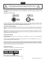
The occupation of the connection-cables is as follows:
Cable Pin International
Brown Live L
Blue Neutral N
Yellow/Green Earth
The earth has to be connected!
If the device will be directly connected with the local power supply network, a disconnection switch with a
minimum opening of 3 mm at every pole has to be included in the permanent electrical installation.
The device must only be connected with an electric installation carried out in compliance with the IEC-
standards. The electric installation must be equipped with a Residual Current Device (RCD) with a maximum
fault current of 30 mA.

00028142.DOC, Version 1.0
17/35
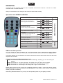
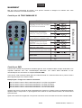
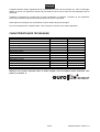
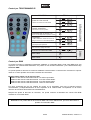
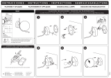
FUNCTION
STAND-ALONE
DMX
Manualcoloradjustment
viathebrightnessoftheRGBLEDs
Automaticchange
speedforchangeofcoloradjustable
Sound-controlledcolorchange*
*onlyavailableforindoormodels
Programs
7staticcolors;colorchangeandcolor
fadewithadjustablespeed
Flash
speedofflashadjustable
BUTTON
MODE
+
-
+
-
+
-
A
+
-
SP
SA
PROG
+
-
SP
+
-
F
BlackOut
turns onandoffLEDs
DMXcontrolledmode
D
Slavemode
SL
DMXstartingaddress
S
09
R
G
B
+
-
OPERATION
The device has two operating modes. It can be operated via IR remote control or it can be run in DMX-
controlled mode via a DMX controller.
After you connected the color changer to the mains, the device starts running.
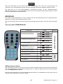
Operation via IR REMOTE CONTROL
DMX-controlled operation
You can control the spots individually via your DMX-controller. Every DMX-channel has a different
occupation with different features. The individual channels and their features are listed under DMX-protocol.
The starting address can be defined via the remote control and is the first channel from which the device will
respond to the controller.
Example for setting the DMX starting address 245:
Step 1: Press button S on the remote control. The red LEDs light, indicating you can start setting the
address.
Step 2: Press button 2. The green LEDs light. The setting of the 100
th
figure was successful.
Step 3: Press button 4. The blue LEDs light. The setting of the 10
th
figure was successful.
Step 4: Press button 5. All LEDs light. The setting of the 1
st
figure was successful.
Please make sure that you do not have any overlapping channels in order to control each device correctly
and independently from any other fixture on the DMX data link. If two, three or more devices are addressed
similarly, they will work similarly.
After having addressed all devices, you may now start operating these via your lighting controller.

00028142.DOC, Version 1.0
18/35
Note: In order to change from DMX-controlled operation back to Stand Alone operation, please disconnect
the device from the DMX-controller.
DMX-protocol
Channel 1 Red
0 - 255 0-100 %
Channel 2 Green
0 - 255 0-100 %
Channel 3 Blue
0 - 255 0-100 %
Channel 4 Dimmer
0 – 255 0-100 %
Channel 5 Flash
0 - 10 No function
11 - 255 0-100 % with increasing speed
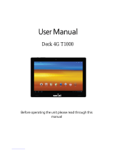
Inserting/Replacing the battery
Open the battery cover on the rear of the remote control and remove it.
If replacing the battery, remove the old battery from the battery compartment.
Leaky or damaged batteries might cause cauterisation when in contact with the skin; therefore, use suitable
protective gloves.
Caution!
Danger of explosion when battery is replaced improperly.
Only replace by the same type or similar types recommended by the manufacturer.
Remove empty battery in accordance with the instructions of the manufacturer.
Insert the battery and make sure that the poles are correct.
Replace the battery cover and close it.
If the device will not be used for a longer period of time, remove the battery in order to avoid battery leakage.
In order to have a long battery life, you should only use alcaline batteries.
BATTERY DISPOSAL NOTICE
Please dispose of old and used batteries properly.
Batteries are hazardous waste and should not be disposed of with regular domestic waste!
Please take old and used batteries to a collection center near you.
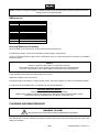
CLEANING AND MAINTENANCE
Disconnectfrommainsbeforestartingmaintenanceoperation!
DANGERTOLIFE!
We recommend a frequent cleaning of the device. Please use a soft lint-free and moistened cloth. Never use
alcohol or solvents!

00028142.DOC, Version 1.0
19/35
There are no serviceable parts inside the device. Maintenance and service operations are only to be carried
out by authorized dealers.
Should you need any spare parts, please use genuine parts.
Should you have further questions, please contact your dealer.
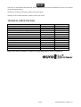
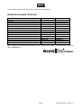
TECHNICAL SPECIFICATIONS
Version: LED T500 RGB LED T1000 RGB
Power supply:
230 V AC, 50 Hz ~ 230 V AC, 50 Hz ~
Power consumption:
16 W 30 W
Maximum ambient temperature T
a
:
45° C 45° C
Maximum housing temperature T
B
(steady state):
55° C 55° C
Min.distance from flammable surfaces: 0,50 m 0,50 m
Min.distance to lighted object: 0,10 m 0,10 m
Number of channels: 5 5
Number of LEDs:
114 10mm 240 10mm
Beam angle: 20°/40° 20°/40°
Protection grade: IP 65 IP 65
Dimensions (LxWxH):
500 x 80 x 170 mm 1000 x 210 x 175 mm
Weight:
3 kg 4.5 kg
Accessories: No.: No.:
EUROLITE IR remote for LED outdoor 51914130 51914130
Button cell battery CR2025 3V for IR remote 14020613 14020613
Please note: Every information is subject to change without prior notice. 21.06.2007 ©
Page is loading ...
Page is loading ...
Page is loading ...
Page is loading ...
Page is loading ...
Page is loading ...
Page is loading ...
Page is loading ...
Page is loading ...
Page is loading ...
Page is loading ...
Page is loading ...
Page is loading ...
Page is loading ...
Page is loading ...
Page is loading ...
-
 1
1
-
 2
2
-
 3
3
-
 4
4
-
 5
5
-
 6
6
-
 7
7
-
 8
8
-
 9
9
-
 10
10
-
 11
11
-
 12
12
-
 13
13
-
 14
14
-
 15
15
-
 16
16
-
 17
17
-
 18
18
-
 19
19
-
 20
20
-
 21
21
-
 22
22
-
 23
23
-
 24
24
-
 25
25
-
 26
26
-
 27
27
-
 28
28
-
 29
29
-
 30
30
-
 31
31
-
 32
32
-
 33
33
-
 34
34
-
 35
35


EuroLite LED T1000 User manual
- Category
- Stroboscopes & disco lights
- Type
- User manual
- This manual is also suitable for
Ask a question and I''ll find the answer in the document
Finding information in a document is now easier with AI
in other languages
- français: EuroLite LED T1000 Manuel utilisateur
- español: EuroLite LED T1000 Manual de usuario
- Deutsch: EuroLite LED T1000 Benutzerhandbuch
Related papers
-
EuroLite DMX LED Operator 4 User manual
-
EuroLite Outdoor Series User manual
-
EuroLite LED T1000 User manual
-
-
-
-
EuroLite DMX Split 4X User manual
-
-
-
Other documents
-
 T'nB CEI150 Datasheet
-
SHOWTEC LED Bar DMX User manual
-
Elta Halogen Lamp User manual
-
-
 BoomToneDJ Outdoor Spot 121 User manual
-
 Ledco 3821 Suspensions Lamps Operating instructions
-
ACB PAMELA Ceiling and Wall Lamps Operating instructions
-
 Ledco 8163 Operating instructions
-
Ledco MODRIAN LED GU10 1x8W Wall Lamp User manual
-
 Social Deck 4G T1000 User manual


