Page is loading ...

Operator's/Installation/Service Manual
for
Low-Floor Transit Vehicles
33778
March 2007
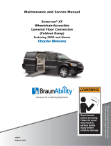
Braun RA300 Transit Ramp
Braun RA300 Transit Ramp
W
A
RNING
ual
Man
Read manual
before operating,
installing or
servicing ramp.
Failure to do so
may result in
serious bodily
injury and/or
property damage.
Braun
RA300 Transit Ramp
Commercial
Braun
RA300 Transit Ramp
®
"Providing Access to the World"
International Corporate Hdqrs: P.O. Box 310 Winamac, IN 46996 USA
1-800-THE LIFT
®
(574) 946-6153 FAX: (574) 946-4670
®

Congratulations
We at The Braun Corporation wish to express our fullest appreciation
on your new purchase.
With you in mind, our skilled craftsmen have designed and assembled
the finest ramp available.
This manual includes operating instructions, installation instructions,
servicing instructions and instructions for troubleshooting, if needed.
Braun ramps are built for dependability and will provide years of service
and mobility independence, as long as the ramp is installed and maintained as
specified, and the ramp is operated by an instructed person.
THE BRAUN CORPORATION
Ralph W. Braun
Chief Executive Officer
Sincerely,

Page 1
CONTENTS
Ramp Terminology
Ramp Terminology Illustration .................................... 2
Ramp Components Terminology Illustration ............. 3
Introduction.................................................................... 4
Terminology................................................................ 4
Direction..................................................................... 4
Ramp Components........................................................ 5
Ramp Actions and Functions....................................... 5
Ramp Operation
Ramp Operation Safety
Safety Symbols ......................................................... 6
Ramp Operation Safety Precautions ..................... 6, 7
Pre-Operation Notes and Details
Ramp Access Doors and Interlocks .......................... 8
Operation Procedured Review .................................. 9
Preventive Maintenance ............................................ 9
Ramp Operation
Ramp Power Operation............................................ 10
Ramp Manual Operation...........................................11
Ramp Passenger Safety .....................................11, 12
Ramp Installation
Installation/Service Safety
Safety Symbols ....................................................... 13
Ramp Operation Safety Precautions ................. 13, 14
Installation Instructions
Installation Requirements......................................... 14
Chassis Requirements............................................. 14
Door Opening........................................................... 15
Obstructions............................................................. 15
Installation Illustrations........................................ 15-17
Electrical Connections.............................................. 18
Electrical Connections Illustration ............................ 19
Maintenance and Lubrication
Lubrication Diagram ................................................... 20
Maintenance and Lubrication Schedule .............. 21-23
Systems Descriptions
Electrical.................................................................. 24, 25
Hydraulics................................................................ 26, 27
Troubleshooting
Troubleshooting Diagnosis Chart ........................ 28-30
Electrical Schematic - BF3248Y & BF3748Y.............. 32
Wiring Diagram - BF3248Y & BF3748Y ...................... 33
Electrical Schematic - BF3248YP............................... 34
Wiring Diagram - BF3248YP ....................................... 35
Hydraulics
Hydraulic Schematic - BF3248Y & BF3748Y.............. 36
Hydraulic Diagram and Parts List - BF3248Y &
BF3748Y ....................................................................... 37
Hydraulic Schematic - BF3248YP............................... 38
Hydraulic Diagram and Parts List - BF3248YP ......... 39
Repair Parts
RA300 Ramp Exploded View
Repair Parts List ....................................................... 40
Exploded View (Fold Out) .............................41A, 42A
6SHFLÀFDWLRQVDQG'LPHQVLRQV ....................41B, 42B
Daily Preventive Maintenance Schedule ................ 43

Page 2
RAMP TERMINOLOGY
Refer to the illustration below and the illustrations on
SDJHIRULGHQWLÀFDWLRQRIFRPSRQHQWVDQGFODULÀFD-
tion of direction terminology. Details regarding lift
model variations, terminology, direction and compo-
nents are provided on pages 4 and 5.
As viewed from outside the vehicle
LEFT
RIGHT
OUT
IN
Ramp Terminology Illustration
®
Vertical
Side Plate
(Barrier)
Pan Weldment
6XEÁRRU
(Fixed)
Inboard Ramp
(Stage One)
Outboard
Ramp
(Stage Two)
Hand
Hold
Drive
Arm
Drive
Arm
Tension
Cable

Page 3
Note: The tension cable, sub
ÁRRUDQGWUDQVLWLRQWKUHVKROG
plate removed from these illus-
trations for clear view.
RAMP TERMINOLOGY
Ramp Components Terminology Illustration
Cylinder
As viewed from outside the vehicle
OUT
IN
RIGHT
LEFT
Pan Weldment
Pump
Ramp Drive Arm
Relays Counter
Cable Tension
Gas Spring
Pump
Ramp Drive Arm
Cam/Microswitch
Assembly
Cylinder
Cable
Pulley
Relays
Counter
Cable Tension
Gas Spring
Cam/Hydraulic
Assembly
(BF3248Y &
BF3748Y Only)
Remote
Hydraulic Block
(BF3248Y &
BF3748Y Only)
Cable Pulley
Tension Cable
Remote Valve Block
(BF3248YP Only)
Cam/Hydraulic
Assembly
(BF3248Y &
BF3748Y Only)
Remote Valve Block
(BF3248YP Only)
Cam/Microswitch
Assembly

Page 4
Introduction
Braun RA300 Series Transit
Ramps (to be referred to as
RA300 throughout this manual)
DUHGHVLJQHGIRUXVHLQORZÁRRU
transit vehicles. The RA300
provides vehicle access to people
with disabilities (wheelchair pas-
sengers or standees using other
type mobility aids). The commer-
cial oriented ramp is ADA compli-
ant (dependant upon installation
height). See the Installation sec-
WLRQIRU$'$VSHFLÀFDWLRQV
The self-contained “drop-in” unit
requires no remote pump, exter-
nal hydraulic lines or pre assem-
bly. The hydraulic and electrical
components are internal and eas-
ily accessible. A single electrical
feed provides the power supply
(12 volt or 24 volt), the ground, a
ramp OUT signal (+), a ramp IN
signal (+) and various indicator
signals.
The RA300 features a 32” wide
ramp in a 34” wide package. A
´ÁRRUSRFNHWµEXLOWLQWRWKHFKDV-
VLVÁRRUV\VWHPDOORZVIRUVLPSOH
installation (dimensional require-
PHQWVVSHFLÀHGLQWKH,QVWDOODWLRQ
section).
7KH5$LVVSHFLÀFDOO\GH-
signed to be operated by an
attendant. The ramp installer
provides an appropriate control
switch for the end user. Con-
squently, the operating instruc-
tions contained in this manual
are generic due to the limitless
variables.
The RA300 provides fully auto-
matic operation of ramp functions.
The electric/hydraulic system is
controlled by two relays which ac-
tivate the hydraulic pump in oppo-
site directions for deploy and stow
functions (powering a dual-acting
hydraulic cylinder). No sensitive
electronic controls or sensors are
required for operation.
All RA300 ramp models feature
gravity down "drift" during the
deploy cycle. When deploying
the ramp, the motor stops running
when the ramp reaches an ap-
proximate 45° angle. The ramp
continues to slowly lower the
remaining distance by the force of
gravity.
5DPSPRGHOQXPEHUVZLWKVXIÀ[
"Y" are hydraulic fold with gravity
down "drift" feature when deploy-
ing and stowing. When stowing
the ramp and it folds inward be-
yond the 15° shut off point, gravity
lowers the ramp to the pan.
Ramp model numbers with suf-
À[<3DUHK\GUDXOLFSRZHUHG
throughout the stow cycle (to full
stow). The hydraulic system re-
mains pressurized while the ramp
is in the stowed position.
The pressure relief valves built
into the pump prohibit the ramp
from lifting (raising) with approxi-
mately 20 pounds or more on the
ramp.
Instructions are provided for
manual operation of the ramp
in event of power or equipment
failure. See Manual Override
on the following page for further
details.
Read and become familiar with
all operation safety precautions,
pre-operation notes and details,
operating instructions and manual
operating instructions before at-
tempting operation.
Terminology: Become familiar
with the terminology that will be
used throughout this manual.
Become familiar with the iden-
WLÀFDWLRQRI5$FRPSRQHQWV
and their functions. Contact your
sales representative or call The
Braun Corporation at 1-800-THE
LIFT
®
if any of this information is
not fully understood.
Direction: The terms “left”,
“right”, “in” and “out” will be used
throughout this manual to indicate
direction (as viewed from the out-
side of the vehicle looking directly
at the ramp). Refer to the Termi-
QRORJ\,OOXVWUDWLRQVIRUFODULÀFDWLRQ
of direction terms.
RAMP TERMINOLOGY

Page 5
Ramp Components
Refer to the Terminology Illustra-
tions on pages 2 and 3.
Pan Weldment (Housing):
The pan is the stainless steel
(casing) mounted in the vehicle
ÁRRUV\VWHPZKLFKFRQWDLQVWKH
hydraulic pump and electrical
components that power the ramp
electric/hydraulic systems. The
À[HGVXEÁRRUFRYHUSURWHFWVWKH
components from above. The
cover is easily removed for ac-
cess to drive components. The
VXEÁRRUSURYLGHVDQDQWLVNLG
surface for entry and exit when
the ramp is deployed. The
RA300 stows (folds) onto the sub
ÁRRUSURYLGLQJDQXQREVWUXFWHG
antiskid surface for entry and exit
when the ramp is not in use.
Ramp Assembly: The ramp
assembly is made of an inboard
ramp section (stage one) and an
outboard ramp section (stage
two). Each aluminum ramp sec-
tion features vertical side plates
and full antiskid surface.
Drive Arm Assembly:
The cylinder driven three stage
drive arm assembly deploys and
stows the ramp assembly.
Ramp Actions and Functions
Deploy: Deploy is the action of
the ramp assembly extending and
unfolding to ground level when
the DEPLOY (OUT) switch* is
activated (*installer supplied).
Stow: Stow is the action of the
ramp assembly raising and fold-
ing inward to stow position when
the STOW (IN) switch* is acti-
vated (*installer supplied).
Stow Position: Stow position
is achieved when the two stage
ramp assembly is fully retracted
and folded (resting fully on the
pan weldment).
Manual Override: Manual
operation is achieved without the
use of any mechanical release or
complicated procedures. Simply
use the Hand Holds provided on
the ramp assembly to manually
deploy or stow the ramp. Mini-
mal physical effort is required to
URXWHWKHK\GUDXOLFÁXLGWKURXJK
the system. Slow steady motion
results in the least resistance and
easy operation. The faster you
attempt to manually operate the
ramp, the greater the resistance.
See Ramp Manual Operation on
page 11 for further details.
RAMP TERMINOLOGY

Page 6
Ramp Operation Safety Precautions
W
A
RNING
If the ramp operating
instructions, manual
operating instructions
and/or ramp operation
safety precautions are
not fully understood,
contact The Braun
Corporation immedi-
ately. Failure to do so
may result in serious
bodily injury and/or
property damage.
Read manual and supplement(s) before operating ramp.
Read and become familiar with all safety precautions, pre-
operation notes and details, operating instructions and
manual operating instructions before operating the ramp.
Note: All transit agency personnel (drivers and ramp at-
tendants) must read and become familiar with the con-
tents of this manual and supplement(s) before operation.
Load and unload on level surface only.
Engage vehicle parking brake before operating ramp.
Provide adequate clearance outside the vehicle to accom-
modate the ramp before opening lift door(s) or operating
ramp.
W
A
RNING
Inspect ramp before operation. Do not operate ramp if you suspect lift damage, wear or
any abnormal condition.
Keep operator and bystanders clear of area in which the ramp operates.
/RDGDQGXQORDGFOHDURIYHKLFXODUWUDIÀF
Open ramp door(s) fully and secure before operating ramp.
Do not overload or abuse. The rated capacity is 300 kilograms (660 pounds).
RAMP OPERATION
W
A
RNING
W
A
RNING
W
A
RNING
W
A
RNING
W
A
RNING
W
A
RNING
W
A
RNING
W
A
RNING
Safety Symbols
SAFETY FIRST! Know That....
C
CAUTION
This symbol indicates
important information
regarding how to
avoid a hazardous
situation that could
result in minor person-
al injury or property
damage.
A
supplements (if included), is pro-
vided for your safety. Familiarity
with proper operation instructions
as well as proper maintenance
procedures are necessary to en-
sure safe, trouble free operation.
Safety precautions are provided
to identify potentially hazardous
situations and provide instruction
on how to avoid them.
All information contained
in this manual and
B
W
A
RNING
This symbol indicates
important safety
information regarding
a potentially hazard-
ous situation that
could result in serious
bodily injury and/or
property damage.
D
Note:$GGLWLRQDOLQIRUPDWLRQSURYLGHGWRKHOSFODULI\RUGHWDLODVSHFLÀFVXEMHFW
These symbols will appear throughout this manual. Recognize the seriousness of this information.

Page 7
Do not activate control switch(es) when anyone is near the area in which ramp operates.
It is the responsibility of the attendant to oversee and assist ramp passengers.
The wheelchair passenger and/or attendant must ensure the ramp is fully deployed
before exiting the vehicle.
Attendants must never operate the vehicle, the ramp or attend to passengers if intoxi-
cated.
Intoxicated passengers should not be allowed to board the vehicle.
Wheelchair passengers must position and secure (buckle, engage, fasten, etc.) the
wheelchair-equipped occupant seat belt before loading onto the ramp.
Be aware of the ramp slope (angle).
Wheelchair passengers should not raise front wheelchair wheels (pull wheelie) when on
the ramp.
The wheelchair must be positioned in the center of the ramp when loading and unloading.
Keep ramp owner’s manual in ramp-mounted vehicle at all times.
0DLQWHQDQFHDQGOXEULFDWLRQSURFHGXUHVPXVWEHSHUIRUPHGDVVSHFLÀHGLQWKLVPDQXDO
E\DXWKRUL]HGFHUWLÀHGVHUYLFHSHUVRQQHO
Never modify (alter) a Braun Corporation ramp.
Do not use accessory devices not authorized by The Braun Corporation.
Do not remove any guards or covers.
If the information contained in this manual is not fully understood, contact The Braun
Corporation immediately.
)DLOXUHWRIROORZWKHVHVDIHW\SUHFDXWLRQVPD\UHVXOWLQVHULRXVERGLO\LQMXU\DQGRUSURS-
erty damage.
RAMP OPERATION
W
A
RNING
Ramp Operation Safety Precautions (continued)
W
A
RNING
W
A
RNING
W
A
RNING
W
A
RNING
W
A
RNING
W
A
RNING
W
A
RNING
W
A
RNING
W
A
RNING
W
A
RNING
W
A
RNING
W
A
RNING
W
A
RNING
W
A
RNING
W
A
RNING

Page 8
Attendants must become familiar
with the vehicle ramp access door
system and interlock(s), as well
as the proper operation of the
ramp.
Vehicle ramp access door con-
ÀJXUDWLRQVDQGRSHUDWLRQSURFH-
dures vary. Ensure the ramp door
is fully open before activating the
ramp (an interlock typically pre-
vents ramp operation unless the
door is fully open). Attendants
and passengers must keep clear
of the area in which the power
door operates. Ensure the path
is clear before closing the door.
Be sure the door is fully closed
before attempting to drive the ve-
hicle (interlocks typically ensure
this).
Interlocks are required by nearly
all transit authorities. Vehicle
interlocks typically prevent vehicle
motion if the ramp is not stowed.
In some cases, the ramp cannot
be operated if interlock conditions
are not met. Interlock require-
ments may include: the vehicle
transmission must be engaged in
Park, the parking brake must be
engaged, the ramp access door
must be fully open and/or others.
Multiple interlocks may exist.
Instructions for operation of
interlocks and door systems will
not be addressed in this manual
due to the variety of procedures
required for operating them.
General instructions for safe
operation of the ramp are pro-
vided. Ramp safety and ramp
passenger safety information is
included. It is the responsibil-
ity of the attendant to properly
open and close the ramp access
door(s), to activate interlock(s), to
properly activate the ramp power
functions as well as assist ramp
passengers.
Do not operate the ramp if you
suspect ramp damage, wear or
any abnormal condition. Dis-
continue use immediately and
contact The Braun Corporation
at 1-800-THE LIFT
®
. One of our
national Product Support repre-
sentatives will direct you to an
authorized service technician who
will inspect the ramp.
Ramp Access Doors and Interlocks
The RA300 Ramp provides
vehicle access to people with
disabilities (wheelchair passen-
gers or standees using other type
mobility aids). The commercial
oriented RA300 Ramp is operated
by the transit vehicle driver/atten-
dant. Unless your transit agency
has a published policy stating that
driver/attendants do not aid ramp
passengers, safe entering and
exiting of ramp passengers is
the responsibility of the driver/
attendant.
As stated in the Ramp Operation
Safety section, all information in
this manual is provided for the
safety of passengers, attendants
and bystanders. Recognize the
seriousness of this information.
Read and become familiar with
all ramp operation safety precau-
tions, pre-operation notes and
details, operating instructions and
manual operating instructions
before attempting ramp opera-
tion procedures or assisting ramp
passengers boarding and exiting
the vehicle.
Pre-Operation Notes and Details
RAMP OPERATION

Page 9
W
A
RNING
Read and become
familiar with all ramp
operation safety
precautions, pre-
operation notes and
details, operating
instructions and
manual operating
instructions prior to
operating the ramp.
If this information is
not fully understood,
contact The Braun
Corporation immedi-
ately. Failure to do so
may result in serious
bodily injury and/or
property damage.
The Braun Corporation recom-
mends that transit agency su-
pervisors and driver/attendants
review the safety precautions and
operation procedures appearing
in this manual with the ramp sales
representative (or vehicle con-
verter) before attempting ramp
operation.
Any questions or concerns can be
answered at that time. Operate
the ramp through all functions to
ensure the proper use and opera-
tion is understood.
Maintenance is necessary to
ensure safe and trouble free
operation. General preventive
maintenance consisting of care-
ful inspections and cleaning the
ramp system should be a part of
your transit agency’s daily service
program. Simple inspections
can detect potential operational
problems.
Operation Procedure Review
Transit agency supervisors
should train and educate all
driver/attendants on the proper
use and operation of the vehicle,
door system, interlock(s), ramp
and ramp passenger safety.
The ramp owner’s/service manu-
al must be stored in the ramp-
equipped vehicle at all times.
Regular preventive maintenance
will reduce potential operation
downtime and increase the service
life of the ramp, as well as possibly
detecting potential hazards.
A generic Daily Preventive Main-
tenance Schedule is provided in
this manual for your transit agen-
cy’s use. The form can be tailored
to your particular application.
Preventive Maintenance:
Exposure to harsh weather, en-
vironmental conditions, or heavy
usage may require more frequent
maintenance and lubrication
procedures.
Preventive maintenance visual
inspections do not take the place
RIWKHSURFHGXUHVVSHFLÀHGLQ
the Maintenance and Lubrication
Schedule provided in this manual.
Refer to the Maintenance and
Lubrication section in this manual
for further details.
RAMP OPERATION

Page 10
W
A
RNING
Provide adequate
clearance outside
of vehicle to ac-
commodate ramp.
Failure to do so may
result in serious
bodily injury and/or
property damage.
Ramp Power Operation
The power ramp is attendant operated and activated
by the control switch provided by the vehicle con-
verter (ramp installer). A momentary contact ramp
control switch (center off) will typically be provided
near the driver. The control switch may be part of a
panel providing other features and controls (power
on/off indicators, LED’s, etc.).
Be certain there is
adequate clearance
outside the vehicle
before deploying
the power ramp.
The ramp opera-
tor (attendant) and
bystanders must
keep clear of the
area in which the
ramp operates and
clear of all mov-
ing parts. Attendants must ensure that passengers
keep clear of the area in which the ramp operates.
Do not attempt to grip or hold the ramp, ramp drive
arm assemblies or the tension cables.
If you are an attendant operating the ramp, it is your
responsibility to oversee and/or assist in performing
safe passenger loading and unloading procedures.
Observe your passengers at all times when they are
entering and exiting the vehicle. Attendants must
be aware of any special needs and/or procedures
required for safe transport of wheelchair passengers.
Do not attempt to load or unload a passenger in
DZKHHOFKDLURURWKHUDSSDUDWXVWKDWGRHVQRWÀW
on the ramp. Do not exceed the 660 pound (300
kilograms) load capacity of the ramp. Passengers
should enter and exit one at a time. The attendant
should not board the ramp with the passenger
except when assistance is required and the load
capacity is not exceeded. Always return the ramp to
the stowed position when not in use.
CAUTION
Allow ramp to deploy
fully before boarding.
Failure to do so may
result in damage.
Deploy Gravity Down Drift (All RA300 models):
When deploying (unfolding) the ramp, the ramp
pump motor stops running when the ramp reaches
an approximate 45° angle (shut off point). The
ramp continues to slowly lower the remaining dis-
tance by the force of gravity (non-powered).
Allow the ramp to unfold (deploy) fully before
boarding the ramp. Forcing the ramp out or down
during the deploy (unfold) function, or boarding
onto the ramp before it is fully-deployed may re-
sult in damage to the ramp and/or drive assembly.
Stow Gravity Down Drift ("Y" ramp models only):
When stowing the ramp and it reaches an approxi-
mate 15° angle (shut off point), gravity lowers the
UDPSWRWKHSDQÁRRU
Before operating the ramp, park the vehicle on
DOHYHODUHDDZD\IURPYHKLFXODUWUDIÀF3ODFH
the vehicle transmission in “Park” and engage the
parking brake. Meet all other interlock conditions
(as equipped). Activate the vehicle “kneel” system
to lower the vehicle (if so equipped). Lowering the
vehicle reduces the slope of the ramp.
RAMP OPERATION
Power Ramp Safety
W
A
RNING
Keep clear of
area in which
ramp operates.
Gravity Down Drift
Note: Pump
motor shut
off points are
microswitch
DGMXVWDEOH

Page 11
Ramp Manual Operation
If you experience power or equipment failure, the
ramp can be manually stowed and deployed. The
RA300 ramp must be manually operated by an at-
tendant.
Two oval-shaped HAND HOLD slots are provided
on the ramp (see Figure A). Carefully unfold and
fold the ramp using the HAND HOLDs.
Keep clear of the area in which the hinged RA300
ramp sections fold and unfold. Keep clear of the
area where the inboard ramp side plates stow in the
SDQÁRRU.HHSFOHDURIWHQVLRQFDEOHVDQGGULYH
arms. Remember to use good body mechanics
when folding and unfolding the ramp.
The safety precautions addressed in the Ramp
Power Operation section apply to manual operation
of the ramp also. Read and become familiar with
all ramp safety precautions.
Note: Minimal physical effort is required to manu-
ally operate the ramp. Slow steady motion results
in the least resistance and easy operation. The
faster you attempt to manually operate the ramp,
the greater the resistance.
Hand
Hold
Use HAND HOLDs to carefully
unfold and fold the ramp.
Keep clear of
hinged areas.
Keep clear of
hinged areas.
Ramp Passenger Safety
Unless your transit agency has a published policy
stating that driver/attendants do not aid ramp
(disabled) passengers, it is the responsibility of
the driver/attendant to ensure that ramp pas-
sengers enter and exit the vehicle on the ramp
in the safest manner.
ADA requirements state that transit drivers/at-
tendants must assist with attaching and removing
wheelchair and occupant restraint belts.
Ramp passengers (wheelchair passengers and
standees), and attendants must use common
VHQVHDQGJRRGMXGJPHQWUHJDUGLQJUDPSVDIHW\
Each wheelchair passenger (or standee) has a
unique set of physical abilities combined with the
physical characteristics of his or her wheelchair (or
other mobility aid) that dictate the method in which
he or she will enter and exit the vehicle.
Wheelchair attendants should be instructed on
any special needs and/or procedures required for
safe transport of wheelchair passengers. Follow all
safety instructions regarding torso restraints, stabil-
ity, balance, weight distribution and use of atten-
GDQWVDVVSHFLÀHGLQWKHRZQHUҋVPDQXDOVXSSOLHG
with the passenger’s wheelchair (or other mobility
aid). Wheelchair passengers must determine,
establish and practice ramp boarding and exiting
procedures under the direction of the their personal
health care professional and wheelchair representa-
tive. Those procedures should be conveyed to the
ramp attendant. Know your passengers abilities
and needs for optimum safety.
Attendants must never operate the vehicle, the
ramp or assist passengers if intoxicated. Intoxi-
cated passengers should not be allowed to board or
exit the vehicle.
Passengers should be positioned in the center of
the ramp at all times. Attendants and ramp pas-
sengers must be able to clearly view the ramp
whenever boarding and exiting the vehicle. The
Figure A
Keep clear of area
where ramp side plates
VWRZLQSDQÁRRU
RAMP OPERATION
Hand
Hold
Keep clear of
tension cables.

Page 12
W
A
RNING
Position and fasten
the wheelchair-
equipped occupant
seat belt before
loading onto the
wheelchair ramp.
Failure to do so may
result in serious
bodily injury and/or
property damage.
attendant and/or wheelchair pas-
senger must ensure the ramp is
fully deployed before exiting the
vehicle. Observe your passen-
gers at all times when they are
entering and exiting the vehicle.
Wheelchair-Equipped Occupant
Seat Belts: Wheelchair passen-
gers should position and buckle
their wheelchair-equipped seat
EHOWWRUVRUHVWUDLQWDVVSHFLÀHG
by the manufacturer, before load-
ing onto a wheelchair ramp.
Different types of disabilities
require different types of wheel-
chairs and different types of
wheelchair-equipped occupant
restraint belt systems (torso re-
straint). It is the responsibility of
the wheelchair passenger to have
his or her wheelchair equipped
with an occupant restraint (seat
belt) under the direction of their
health care professional.
Stabilizing Wheelchairs: Pow-
ered and manual wheelchairs
are designed to remain upright
and stable during normal opera-
tion. All activities which involve
movement in a wheelchair have
an effect on the combined center
of gravity of the occupant and
wheelchair. Be aware of the ramp
slope (angle). The slope of the
ramp has a direct effect on the
center of gravity. The wheelchair
passenger’s center of gravity and
their ability to maintain stability
and balance must be kept in mind
by the wheelchair passenger and
the attendant.
The aid of an attendant stabilizing
the wheelchair is recommended
for optimum safety. Wheelchair
passengers who are unable to
maintain stability and balance
should not board a ramp without
assistance. Counterbalance
devices (anti-tippers) may be
available from the wheelchair rep-
resentative to enhance stability
and balance.
Wheelchairs should be operated
at a slow and constant speed
when on the ramp. Wheelchairs
should not accelerate suddenly
RAMP OPERATION
W
A
RNING
Be aware of
ramp slope.
52217
Ramp Passenger Safety (Continued)
when on the ramp. Wheelchair
passengers should not raise the
front wheelchair wheels (pull
wheelie) when on the ramp.
Wheelchair passengers who
intend to enter and exit the
vehicle without the assistance of
an attendant must determine the
safest and most practical method
and orientation of entering and
exiting based on the physical
characteristics of their personal
wheelchair and his or her physical
capabilities to maintain stability
while the wheelchair is in motion
on the ramp.
Wheelchair Attendants: When
assisting a wheelchair occupant,
remember to use good body me-
chanics. When the wheelchair is
on the ramp, the attendant must
grasp the push handles (or other)
securely. Detachable wheelchair
parts such as arms or leg rests
must never be used for hand
holds or lifting supports. Doing
so could result in the parts being
inadvertently detached from the
wheelchair resulting in possible
injury to the wheelchair occu-
pant and/or the attendant.

Page 13
W
A
RNING
If installation, main-
tenance or repair
procedures cannot
be completed ex-
actly as provided in
this manual or if the
instructions are not
fully understood,
contact The Braun
Corporation immedi-
ately. Failure to do
so may result in
serious bodily injury
and/or property
damage.
W
A
RNING
Read this manual and supplement(s) before performing instal-
lation, operation or service procedures.
,QVWDOODWLRQVSHFLÀFDWLRQVDQGGLPHQVLRQVPXVWEHPHW
Remove any obstructions within the ramp mounting/operating
area prior to beginning installation procedures.
Do not operate ramp prior to positive securement of the pan.
Check for obstructions such as gas lines, wires, exhaust, etc.
before drilling or cutting during installation procedures.
Route all cables clear of exhaust system, other hot areas,
moving parts, wet areas, etc.
5LVNRIHOHFWULFDOVKRFNRUÀUH8VHH[WUDFDUHZKHQPDNLQJ
electrical connections. Connect and secure as outlined in
Installation Instructions and Wiring Diagrams.
CAUTION
W
A
RNING
W
A
RNING
W
A
RNING
W
A
RNING
Installation / Service Safety Precautions
RAMP INSTALLATION
Safety Symbols
SAFETY FIRST! Know That....
C
CAUTION
This symbol indicates
important information
regarding how to
avoid a hazardous
situation that could
result in minor person-
al injury or property
damage.
A
supplements (if included), is pro-
vided for your safety. Familiarity
with proper operation instructions
as well as proper maintenance
procedures are necessary to en-
sure safe, trouble free operation.
Safety precautions are provided
to identify potentially hazardous
situations and provide instruction
on how to avoid them.
All information contained
in this manual and
B
W
A
RNING
This symbol indicates
important safety
information regarding
a potentially hazard-
ous situation that
could result in serious
bodily injury and/or
property damage.
D
Note:$GGLWLRQDOLQIRUPDWLRQSURYLGHGWRKHOSFODULI\RUGHWDLODVSHFLÀFVXEMHFW
These symbols will appear throughout this manual. Recognize the seriousness of this information.
W
A
RNING
0HHWDOOUDPSSRVLWLRQLQJDQGFOHDUDQFHVSHFLÀFDWLRQVDVGHWDLOHGLQWKH3RVLWLRQLQJDQG
Clearance Checklist before operating ramp.
Maintenance and repairs must be performed only by authorized service personnel.
Perform maintenance and lubrication procedures exactly as outlined in the Maintenance
and Lubrication Schedule contained in this manual.
W
A
RNING
W
A
RNING
W
A
RNING

Page 14
Disconnect the power cable at the battery prior to servicing.
Keep hands, arms and all other body parts clear of moving parts.
Never modify (alter) a Braun Corporation ramp.
Replacement parts must be Braun authorized replacements.
Never install screws or fasteners (other than factory equipped).
Whenever replacing a hydraulic cylinder or seals, deploy ramp fully.
)DLOXUHWRIROORZWKHVHVDIHW\SUHFDXWLRQVPD\UHVXOWLQVHULRXVERGLO\LQMXU\DQGRUSURS-
erty damage.
Installation/Service Safety Precautions (Continued)
W
A
RNING
Read this manual,
before performing
installation, operation
or service procedures.
Failure to do so may
result in serious
bodily injury and/or
property damage.
Installation Requirements
Braun RA300 Ramps must be
installed and serviced by a Braun
authorized service representa-
tive who has attended and been
FHUWLÀHGE\7KH%UDXQ&RUSRUD-
tion Sales and Service School for
Braun Mobility Products.
SRFNHWµFRQÀJXUDWLRQQRWVXS-
plied).
Slope:7KHSRUWLRQRIWKHÁRRU
where the ramp mounts must
slope at an approximate 8° angle
(see Figure C).
Outboard Support Tube: An
outboard support tube must be
positioned under the outboard
edge of the opening (minimum
1-1/2” x 2” steel tube). See Fig-
ures C and D. The recommended
height of the support tube is 12”
above ground level. Kneeling
Vehicles: This dimension mea-
sured with suspension lowered.
ADA: Installations with the sup-
port tube positioned higher than
12” above ground level may not
comply with ADA ramp slope
requirements.
Some OEM chassis meet these
VSHFLÀFDWLRQV7KH5$UDPS
was designed to conform to these
VSHFLÀFDWLRQV
The ramp pan horizontal bor-
GHUOLSVHWVRQWKHÁRRUSRFNHW
SHULPHWHUIUDPHZRUNVXEÁRRU
HWF7KHÀQLVKHGÁRRULQJFDQEH
cut to conform to the border of the
SDQIRUDÁXVKWUDQVLWLRQVXUIDFH
IURPUDPSWRÁRRU
RAMP INSTALLATION
W
A
RNING
W
A
RNING
W
A
RNING
W
A
RNING
W
A
RNING
W
A
RNING
Chassis Requirements
The Braun RA300 Ramp is de-
VLJQHGIRUXVHLQORZÁRRUWUDQVLW
YHKLFOHV$´ÁRRUSRFNHWµPRXQW-
ing hole) built into the chassis/
ÁRRUV\VWHPDOORZVIRUVLPSOHLQ-
stallation (accepts “drop-in” unit).
The Floor Pocket Clear Open-
ing DimensionsDUHVSHFLÀHGRQ
pages 15 and 16. See Figures B,
C, D and E.
The ramp installer must provide
an appropriate framework in the
applicable location in the vehicle
(aligned center with passenger
door opening). Ramp assembly
mounting hardware and/or brack-
ets are directly dependant upon
WKHYHKLFOHFKDVVLVDQG´ÁRRU
Read and become familiar with
the operating instructions and the
installation instructions contained
in this manual before beginning
installation, operation or service
procedures.
W
A
RNING

Page 15
RAMP INSTALLATION
Door Opening: Open the door(s)
fully and check the clear door
opening width dimension. Speci-
ÀHGPLQLPXPFOHDUGRRURSHQ-
ing width must be provided (34"
for 32" ramps and 39-1/2" for 37"
ramps). See Figure F.
Door(s) must open outward.
When closed, the door(s) should
align with and conform to the
outboard edge of the ramp pan
(rubber seal on bottom of door).
Minimum Clear Door Opening
'LPHQVLRQVDUHGHÀQHGDVÀQ-
ished door opening, including any
LQWUXVLYHGRRUMDPEVKHDGHUV
sills or hinges.
Obstructions: Any intrusive ob-
structions within the door opening
or the ramp mounting/operating
area (such as seats, molding,
lights, brackets, etc.) must be re-
moved. Trim or molding that cre-
ates an uneven mounting surface
should be removed. The molding
FDQEHPRGLÀHGWRÀWDURXQGWKH
ramp pan horizontal border (lip).
There must be a minimum 1/8”
clearance between the de-
ployed ramp assembly and the
YHKLFOHÁRRURUDQ\REVWUXFWLRQ
RQWKHÁRRUVXFKDVDUXEEHUVLOO
or threshold).
Outboard
Support Tube
“Floor Pocket” Clear Opening Dimensions
Figure B
Outboard Support Tube: Recom-
mended Height: 12” above ground
level. Kneeling Vehicles (measured
with suspension lowered).
23"
Ý
12"
)ORRU6ORSH Ý
ADA: Installations with support tube
positioned higher than 12” above
ground level may not comply with
ADA ramp slope requirements.
7KHSRUWLRQRIWKHÁRRUZKHUHWKH
ramp mounts must slope at an ap-
proximate 8° angle.
Figure C
BF3248Y & BF3248YP 34-3/4"
BF3748Y 39-3/4"
Chassis
SUPPORT TUBE
Floor Pocket
Framework
Outboard
Support Tube
Figure D
Structure: Minimum
1-1/2” x 2” steel tub-
ing (or equivalent).

Page 16
Chassis
SUPPORT TUBE
23"
Floor Pocket
Width
Floor Pocket Width:
34-3/4
" for 32" Ramp
39-3/4
" for 37" Ramp
RAMP INSTALLATION
Note: See Figure
B and C also.
Figure E
"Floor Pocket" Clear Opening Dimensions
As viewed from outside the vehicle
Left
Right
Out
In
Chassis
Chassis
C
L
C
L
Minimum Door Opening Width:
34
" for 32" Ramp
39-1/2
" for 37" Ramp
MINIMUM
DOOR OPENING
WIDTH
Figure F
9HKLFOHFKDVVLV´ÁRRU
SRFNHWµFRQÀJXUDWLRQ
must be aligned cen-
ter with door opening.
Door(s) must
open outward.
Clear Door Opening Width Dimension

Page 17
RAMP INSTALLATION
Installed Ramp - Stowed
Chassis
Chassis
SUPPORT TUBE
Stowed RA300
Ramp positioned in
WKH´ÁRRUSRFNHWµ
Figure G
Installed Ramp - Deployed
There must be a minimum 1/8” clearance
between the deployed ramp assembly and
WKHYHKLFOHÁRRURUDQ\REVWUXFWLRQ on the
ÁRRUVXFKDVDUXEEHUVLOORUWKUHVKROG
Chassis
Chassis
SUPPORT TUBE
®
Figure H
As viewed from outside the vehicle
Left
Right
Out
In

Page 18
W
A
RNING
W
A
RNING
Risk of electrical
shock! Use extra
care when making
electrical connec-
tions.
5LVNRIHOHFWULFDOÀUH
Use extra care when
making electrical
connections.
W
A
RNING
Cable
Clip
Cable Tie
Cable
(typical)
Vehicle
Floor
Vehicle
Floor
Framing
Member
Self-Tap Screw
Secure all cables using cable
ties and/or cable clips (mount
clips with self-tap screws).
Chassis Ground Corrosion:
When mounting chassis ground
cables, remove undercoating, dirt,
rust, etc. from the framing member
around the mounting holes. Apply
a protective coating to mounting
holes to prevent corrosion. Apply
grease to ground cable terminals
and mounting hardware. Failure
to do so will void warranty of
certain electrical components.
An 8-pin Deutsch connector
is mounted at the back of the
RA300 ramp. A mating connector
(male plug) is supplied with the
ramp. The power supply (12 volt
or 24 volt), the ground, a ramp
OUT signal (+) and a ramp IN sig-
nal (+) must be terminated in the
supplied Deutsch connector.
The ramp installer provides an
appropriate control switch for the
end user. A momentary contact
ramp control switch (center off)
will typically be mounted near the
driver. The control switch may
be part of a panel providing other
features and controls (power on/
off indicators, LED’s, etc.).
Make electrical connections as
shown in Figure K page 19. Strip
wires, crimp and install contacts
DVVSHFLÀHGLQLQVWUXFWLRQVVXS-
plied with 8-pin Deutsch connec-
tor.
The Positive (+) “battery” lead wire must
be protected by an in-line 30 ampere
fuse or circuit breaker (installer pro-
vided).
Do not connect the power “battery” lead
wire to the battery until all other connec-
tions are made.
Connect the 8-pin Deutsch male plug to
the mating Deutsch connector mounted
at the back of the pan.
Carefully connect the power “battery”
lead wire to the Positive (+) battery post.
Electrical Connections
Figure J
RAMP INSTALLATION
Route cables clear
of exhaust system,
other hot areas and
moving parts. Failure
to do so may result
in serious bodily
injury and/or property
damage.
/