Page is loading ...

SNOWPLOWS
by Meyer
Out-Front-Electric Hydraulics
Owner’s Manual

Table of Contents Page
Introduction . . . . . . . . . . . . . . . . . . . . . . . . . . . . . . . . . . 2
Tripedge Series
Get to Know Your Diamond MDII Snowplow . . . . . 3-6
Get to Know Your Diamond Snowplow . . . . . . . . . . 7-8
Blade Specifications . . . . . . . . . . . . . . . . . . . . . . . 9-10
Controls & Operating Instructions . . . . . . . . . . . . 11-12
Diamond MDII Snow Plow Instructions . . . . . . . . . .13-16
Snowplow Operation . . . . . . . . . . . . . . . . . . . . . . . . . . 17
Removing & Attaching Snowplow . . . . . . . . . . . . . . . . 17
General Maintenance & Adjustments . . . . . . . . . . . 18-19
Troubleshooting . . . . . . . . . . . . . . . . . . . . . . . . . . . 20-22
Efficient Snow Clearance . . . . . . . . . . . . . . . . . . . . . . . 23
Keep Snow Under Control . . . . . . . . . . . . . . . . . . . . . . 23
Selecting Equipment . . . . . . . . . . . . . . . . . . . . . . . . . . 24
Hourly Snow Clearing Capacities . . . . . . . . . . . . . . . . 24
Plow with the Storm . . . . . . . . . . . . . . . . . . . . . . . . . . . 25
Establishing Snow Clearance Plans . . . . . . . . . . . . . . 26
Snowplowing Tips from the Pros . . . . . . . . . . . . . . 27-29
Minerals and Chemicals for Ice Control . . . . . . . . . . . 30
Ice Control Spreaders . . . . . . . . . . . . . . . . . . . . . . . 31-32
Fast Moving Parts List . . . . . . . . . . . . . . . . . . . . . . 33-34
Accessories . . . . . . . . . . . . . . . . . . . . . . . . . . . . . . 35-36
Specifications . . . . . . . . . . . . . . . . . . . . . . . . . . . . . 37-38
Warranty Card . . . . . . . . . . . . . . . . . . . . . . . . Back Cover
Diamond Snowplows

2
Diamond snowplow equipment should only be used on vehicles equipped with the manufacturer’s snowplow preparation packages. Snowplowing without the original
snowplow preparation package may damage your vehicle and the added weight of the equipment may impair the operation and control of the vehicle. Snowplowing with a
vehicle that the manufacturer does not recommend for that purpose may void your new vehicle warranty. If your vehicle is not originally equipped with the snowplow
preparation package, additional equipment may be necessary before snowplowing. Owners of these vehicles should consult their truck dealer before purchase or
installation of equipment. CAUTION: The installation, on any vehicle, of these parts is not a full substitute for the original equipment snowplow preparation package.
Introduction
Snow, despite the beauty it may impart to a bleak winter
landscape, poses the dual threat of inconvenience and danger.
The environmental conditions associated with snow, not to
mention the health hazards and economic loss it may impose,
seriously endanger thousands of lives annually. Business and
industry suffer, and millions of snowbelt residents may be
affected by a single snowstorm.
Diamond Equipment has published this manual to help you get
maximum performance from your Diamond Snowplow and
familiarize you with the features designed for efficiency and
safety; be sure you recognize and understand them. Follow
recommended operation and maintenance instructions, so
when the storm hits, your Diamond Snowplow will be ready and
you will know how to plow like a pro. Do not equip any vehicle
with a snowplow without consulting manufacturer's
recommendations.
Vehicles with Diamond Snowplows installed may be so
equipped as to meet vehicle manufacturers' specifications and
recommended options for snowplowing use. Most vehicle
manufacturers insist that vehicles which are to be used for
snowplowing be equipped with certain options and
accessories, and it is so stated in vehicle manufacturer
specifications for snowplow application.
WARNING: Deployment of an air bag while using a Diamond
snowplow will not be covered under Diamond Equipment
warranty.
We also recommend that, for optimum performance, vehicles
used for snowplowing be equipped with:
• Four-Wheel Drive
• Minimum 60 Amp Alternator or larger
• Minimum 70 Amp Battery or larger (550 C.C.A.)
• Mud and Snow Tires
• Increased Radiator Cooling
• Automatic Transmission
• Transmission Cooler
• Power Brakes
• Power Steering
Under the continuing Diamond Product Improvement Plan,
Diamond Equipment reserves the right to change design details
and construction without prior notice and without incurring any
obligation.

3
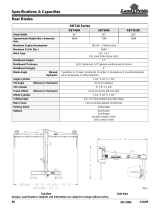
1. Blade
Steel or Polyethylene sheet is bump and corrosion resistant. Built
to last.
2. Adjustable Tripedge Extension Springs
Tripedge gives way when objects are struck at ground level.
Note: Trip Spring tension should be checked on a regular basis
during the snowplowing season. See page 18 under
SNOWPLOW Paragraph 4 for more information.
3. Power Angling Cylinders (1-1/2" x 10")
Hydraulically positions the moldboard straight, or to right or left.
4. Cutting Edge (Optional)
Replaceable, high carbon steel provides extra long operating life.
Recommended for commercial plowers.
5. Wear Shoes
Wear Shoes are an integral part of the Tripedge to reduce wear.
6. Pushframe
Designed to attach the snow plow to the vehicle, to pivot blade
for angle plowing, and to hold plow at proper distance in front of
vehicle.
7. Upper/Lower Pivot Pins
Pins that attach blade to pushframe.
8. Clevis Frame
Allow snow plow assembly to be attached or detached from
vehicle in minutes.
9. MDII
®
Lift Frame
Allows for fast, complete removal of front end hardware, snow plow
lights and hydraulic unit in one complete module.
10. Attaching Pins
Pull 4 blue pins to remove complete assembly or pull 2 yellow pins to
remove moldboard assembly.
11. Lift Arm
Dual Chain locks in position to lift snow plow.
WARNING: LIFT ARM EXTENDS BEYOND BUMPER OF VEHICLE.
TO MINIMIZE DAMAGE FROM A FRONT END COLLISION, LIFT
ARM SHOULD BE REMOVED FROM VEHICLE WHEN SNOW PLOW
IS REMOVED.
12. Diamond Snow Plow Lights
Complies with the Federal Motor Vehicle Safety Standards.
13. Electric Hydraulic Power Unit (E-60H, E-57H)
Operates snow plow hydraulically- raises, lowers, angles, holds and
floats moldboard in plowing position.
14. Sno-Flo® Powder Coat
Baked on finish that looks like glass, provides an extremely hard, low
friction surface that outlasts ordinary paint by a large margin.
15. Crankstand
Positions Moldboard and Lift Frame for easy attaching and detaching.
16. Hydraulic Cover
Protects the Hydraulic Unit from the elements and also enhances the
appearance of your vehicle.
Get to know your Diamond MDII
®
Snow Plow

4

5
CRANKSTAND STORAGE
To store Crankstand on the Lift Frame slide the tube that is attached
to the side of the Crankstand over the receiver tube on the driver's
side of the Lift Frame. Insert the chain locking pin through the vertical
holes on both the tubes. Note: Crankstand should always be fully
retracted (up) and be pinned in the vertical transport position
when not In use. Receiver Tube Cap may be placed over the driver
side transport tube while the Crankstand is in use on the A-Frame.
The Receiver Tube Cap may also be switched over to the Adjustment
Tube of the A-Frame when the Crankstand is mounted to the Lift
Frame.
Storage of the Crankstand is the responsibility of the operator.
The stand can be stored on the lift frame in the retracted
position to the driver's side transport tube or inside the vehicle
cab.
HYDRAULIC COVER
Install Black Hydraulic Cover before installing the Lift Assembly to
the Lift Frame. Begin by sliding the Hydraulic Cover down over the
Lift Ram. Slide the side covering the motor carefully over the motor,
do not force or stretch the Hydraulic Cover; it will fit comfortably over
all parts of the Hydraulic Unit. Feed the three coil wires (red, green
and black) through the hole located on backside of cover. Route
coupler weather plugs through holes in cover where power angling
hoses enter. Snap Cover together. Caution: Care should be taken
with the installation and or removal of the Hydraulic Cover, including
partial removal when repairs are performed on the Hydraulic Lift Unit.
Tearing of the Hydraulic Cover for any reason will not be covered
under the Diamond Warranty.
ATTACHING MOLDBOARD ASSEMBLY ONLY
Attach A-Frame to Lift Frame by connecting Crankstand to the
adjustment tube in the center of the A-Frame Frame. Insert the
chained locking pin all the way through the vertical holes on both the
tubes. Crank up A-Frame until the holes on the back ears of the A-
Frame are about 12” off the ground. Pull out the Yellow Handle Pins
on both sides of the Lift Frame. Twist handle slightly to the right or
left disengaging the pin. Pull truck up to the A-Frame / Moldboard
assembly aligning the A-Frame ears between the two lift frame plates
until contact is made with the Clevis Frame. Once you feel contact,
push the moldboard assembly a few inches forward, this insures
proper alignment so that the A-Frame is square to the Clevis Frame.
Adjust the Crankstand up until the front of the truck raises slightly.
Rotate the Yellow Handled Pins so that the small leg realigns with the
slot, engaging the pin. The spring loaded pin should snap into place
locking the A-Frame to the lift frame. Note: If pins do not properly
engage move the truck slightly forward a few more inches and/or
adjust (raise or lower) the Crankstand until pins lock into place. If
only one pin should engage, retract the stand to the full upright
position. Remove the Crankstand from the A-frame by removing the
chained locking pin. Reattach the Crankstand to the transport tube
on the driver's side of the Lift Frame in the vertical transport position.
Attach the Lift Chain to the Lift Arm through the two hooks on the lift
arm. Adjust the lift chain at the lift arm so that there are 2-3 links of
slack. This ensures that the plow blade will lift fully and be able to
follow the ground contour while plowing. Raise the plow with the
hydraulics and swing the moldboard slightly left or right until the pin
engages.

6
DETACHING THE COMPLETE ASSEMBLY
Leave control switch in lower float position and push down on the
Lift Arm. Disconnect the electrical plug and slip on weather caps
over both ends. Attach Crankstand to the adjustment tube in the
center of the A Frame using the chained locking pin. Caution:
Crankstand must be secured at all times. Adjust the Crankstand
down until the bottom of stand touches the ground. Pull and twist the
two rear Blue Handle Pins to disengage. Next pull and twist the two
front Blue Handle Pins to disengage. If the pins do not pull easily,
adjust stand up or down slightly to remove tension on the pins until
they disengage. At this time the lift frame should be leaning forward
slightly, at rest on the top of the Crankstand. Pull truck away.
DETACHING MOLDBOARD ASSEMBLY ONLY
Leave control switch in lower float position and push down on the
Lift Arm. Disconnect hydraulic couplers and Lift Chain from Lift Arm.
Attach Crankstand to the adjustment tube in the center of the A-
Frame using the chained locking pin. Caution: Crankstand must be
secured at all times. Adjust the Crankstand down until the bottom
of stand touches the ground. Pull and twist the Yellow Handled Pins
to disengage. If the pins do not pull easily, adjust stand up or down
slightly to remove tension on the pins until they disengage. Pull truck
away.
ATTACHING THE COMPLETE ASSEMBLY
Check that all four Blue Handle Pins are disengaged. Drive the truck
up to the MDII assembly centering the hood of the truck to the lift
arm to assure proper alignment with lift frame guide plates until
contact is made. Once contact is made drive forward, pushing the
assembly a few inches. This insures the A-Frame is square to the
Clevis Frame for proper pin attachment. Adjust the Crankstand up
until the front of the truck raises slightly. The rear Blue Handle Pins
should now be aligned with the rear holes on the clevis frame. Twist
all Blue Handle Pins so that the small leg re-aligns with the slot,
engaging the pins. The rear spring loaded pins should snap into
place. Note: If pins do not lock immediately the A-Frame is not
square to the Clevis Frame. Move truck slightly forward and/or adjust
the Crankstand up or down until rear pins engage. Once the back
pins are locked push the top of the Lift Frame towards the truck
locking the front pins to the clevis frame. Remove the Crankstand
from the A-frame by removing the chained locking pin. Reattach the
Crankstand to the transport tube on the driver's side of the Lift
Frame in the vertical, retracted position. Caution: Crankstand must
be secured at all times. Reattach the one step electrical
connection.

7
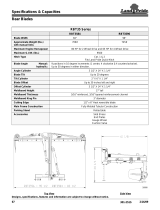
1. Blade
High strength steel. Built to last.
2. Adjustable Tripedge Extension Springs
Tripedge gives way when objects are struck at ground level.
NOTE: Trip spring tension should be checked on a regular basis
during the snowplowing season. See Page 18 under
SNOWPLOW Paragraph 4 for more information.
3. Power Angling Cylinders
Enables the operator to hydraulically position the moldboard
straight, or to right or left, by simply activating the fingertip
control switch.
4. MDII Attaching System
Rubber coated stainless steel pins give you the choice of
removing the plow, mount, hydraulics, and lights (blue pins) or to
remove only the plow (yellow pins).
5. Cutting Edge (optional)
Replaceable, high carbon steel provides extra long operating life.
Recommended for commercial plowers.
8. Wear Shoes
Wear shoes are an integral part of the tripedge to reduce wear.
7. Electric Hydraulic Power Unit
Operates snowplow hydraulically - raises, lowers, angles, holds
and floats blade in plowing position.
8. Pushframe
Designed to attach snowplow to vehicle, to pivot blade for angle
plowing, and to hold plow at proper distance in front of vehicle.
9. Upper/Lower Pivot Pins
Pins that attach blade to pushframe.
10. Lift Arm
Dual chain locks in position to lift snowplow. WARNING: Lift arm
extends beyond bumper of vehicle. To minimize damage
from a front-end collision, lift arm should be removed from
vehicle when snowplow is removed.
11. MDII
®
Mounting System
Allows for fast, complete removal of all front end hardware,
snowplow lights, hydraulic unit, moldboard, sector and
pushframe, in one complete module.
12. Snowplow Lights
Lights and brackets comply with the Federal Motor Vehicle
Safety Standards.
13. Tubular PULL-AWAY™ Mounting System
Allows for fast removal of all snowplow components in two
complete, easy to manage, modules.
14. Tubular PULL-AWAY™ Easy Hitch™ System
Allows moldboard, sector and pushframe to be detached and
attached as a separate module in minutes.
Get to know your Diamond Tripedge Snowplow

8
1
2
5
6
3
8
9
11
10
12
4
E-60H
E-57H
13
14
MDII
®
Mounting System
Pull-Away™ Easy Hitch™
Mounting System

9
TRIPEDGE SERIES
Model 7.5
For 1/2 and 3/4 ton 4x4 Standard Duty
Pickups and Sport Utility Vehicles
STEEL MOLDBOARD SPECIFICATIONS
BLADE WIDTH 7 1/2’
BLADE HEIGHT 27 5/16’’
GAUGE STEEL 12 Gauge
VERTICAL RIBS 6
TYPE OF SPRINGS Extension (4)
NUMBER OF TRIP-EDGE PlNS 6
CUTTING EDGE (OPTIONAL) 2
PLOW WIDTH AT FULL ANGLE 81’’
PUSHFRAME 3” x 2” x 3/16”
PIVOT PIN DIAMETER 1 3/16”
POWER ANGLING RAMS 1 1/2’’ x 10”
AVERAGE SHIPPING WEIGHT 600 lbs.
*weight is based on average depending on specific mounting
POLY MAX MOLDBOARD SPECIFICATIONS
BLADE WIDTH 71/2'
BLADE HEIGHT 29”
MOLD BOARD SHEET THICKNESS 3/8" U.H.M.W. Polyethylene
VERTICAL RIBS 6
TYPE OF SPRINGS Extension (4)
NUMBER OF TRIP-EDGE PINS 6
CUTTING EDGE(OPTIONAL) 2
PLOW WIDTH AT FULL ANGLE 81"
PUSHFRAME 3” x 2” x 3/16’’
PIVOT PIN DIAMETER 1 3/16’’
POWER ANGLING RAMS 1 1/2” x 10”
AVERAGE SHIPPING WEIGHT * 625 Lbs.

10
STEEL MOLDBOARD SPECIFICATIONS
BLADE WIDTH 8.0' 8.5' 9.0' HML-10 10’ DAGT-10 10’
BLADE HEIGHT 29 3/8” 29 3/8” 29 3/8” 32” 32”
GAUGE STEEL 11 Gauge 11 Gauge 11 Gauge 7 Gauge 7 Gauge
VERTICAL RIBS 6 6 6 7 7
TYPE OF SPRINGS Extension (4) Extension (4) Extension (4) Extension (6) Extension (6)
NUMBER OF TRIP-EDGE PINS 6 6 6
CUTTING EDGE (OPTIONAL) 2 2 3
PLOW WIDTH AT FULL ANGLE 86” 92” 97"
PUSHFRAME 3" x 2” x 3/16" 3” x 2” x 3/16” 3” x 2" x 5/16"
PIVOT PIN DIAMETER 1 3/16” 1 3/16” 1 3/16”
POWER ANGLING RAMS 1 1/2" x 10" 1 1/2” x 10” 1 1/2” x 10” 2” x 12” 2” x 12”
AVERAGE SHIPPING WEIGHT* 800 Lbs. 825 Lbs. 875 Lbs.
*weight is based on average depending on specific mounting
TRIPEDGE SERIES
Models 8.0, 8.5, 9.0
For 3/4 and One Ton 4x4 Standard
Duty Pickups and Cab-Chassis Vehicles

11
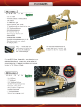
II. Controls and Operating Instructions
Tripedge Series
Special Features
1. Diamond's unique dual pivot pins and diagonal bracing system distribute plow loads better and reduce stress on the
pushframe and cylinders.
2. Diamond's tripedge gives way when objects are struck at ground level. Diamond's rigid moldboard system keeps the blade
upright and plowing until your truck loses traction. Fig. 2.
3. Diamond Snowplows have a more pronounced curve in the blade design which means a better job in throwing snow.
4. Diamond's heavy duty undercarriage support system uniformly distributes snow plowing loads to the vehicle frame.
5. Diamond's unique wear shoes are engineered to load up into the tripedge angle while plowing.
6. Dual chain hooks on the lift arm provide easier hookup and greater stability of the blade.
7. Pivot Pins are 1 3/16" diameter with one-piece construction to eliminate welded-on washers.

12
TRIP-EDGE
Fig. 2

13
Diamond® ™ Snowplow Instructions
CHOICE 1: Removing MDII (Entire Mount)

14
CHOICE 1: Attaching MDII (Entire Mount)

15
CHOICE 2: Removing MDII (Moldboard Only)

16
CHOICE 2: Attaching MDII (Moldboard Only)

17
Snowplow Operation
The snowplow should only be in operation when the vehicle ignition switch
and the Electro-Touch® control switch are in the "ON"
position. Care should be taken to insure that the Electro-
Touch® control switch is kept dry and free from moisture
during normal operation.
When the Electro-Touch® control switch is turned "On,"
yellow lights illuminate the location of the individual touch
pads for the functions of the snowplow: (Up), (Angle Left),
(Angle Right), and (Down).
Lowering of the snowplow an inch at a time is possible by tapping the down
arrow in short intervals. Holding down the down arrow will activate a green
light located in the upper left corner of the Electro-Touch® switch. This
green light indicates the snowplow is now in the Lower/Float position. In this
position the snowplow will be able to follow the contour of the road and the
snowplow can also be angled to the left or right. Touching the up arrow
automatically cancels the Lower/Float position.
This switch is short circuit and temperature protected. All wire connections
must be securely plugged together. If any of these conditions exist, the red
overload LED will light. The overload LED (red light) is located in the upper left
corner below the float light of the Electro-Touch® switch. Reset is
accomplished by turning off the ignition switch or by turning the power switch
off momentarily and then back on. If an overheating temperature condition
exists, it will be necessary to allow the unit to cool down for approximately 2
minutes. If the overload light is still illuminated after attempts to reset the
switch have failed, contact your nearest authorized Diamond Distributor for
repairs.
Note: On Model E-60 only to regulate the lower speed, locate the lower adj.
screw on page 19, Fig. 0-3. Turn adj. screw in to slow down or out for faster
lower speed. Adjustments must be made with moldboard on the ground.
This feature is not available on model E-57.
CAUTION: When the snowplow is not in operation, the Electro-Touch®
Control Switch should be in the "OFF" position.
Over-the-Road Operation
Based on the experience of our representatives and other background, we
advise a maximum transporting speed of 40 m.p.h. or locally regulated
speeds, which ever is less, dependent upon road conditions. The operators
should, of course, maintain a safe stopping distance and adequate passing
clearance at all times.
When transporting the snowplow to avoid engine overheating, angle the
moldboard completely, carrying it as low as permitted for safety by road and
surface conditions.
Removing Moldboard Assembly
1. Be sure moldboard is on ground! The chain can have a small amount of
tension to help support the back of the pushframe.
2. Pull hook-up pins in pushframe outward and turn to hold in place.
3. Lower lift ram all the way and detach chains from lift arm. Reverse the
above procedure to reattach snowplow to vehicle.
4. WARNING: Lift arm extends beyond bumper of vehicle. To minimize
damage from a front-end collision, lift arm should be removed from
vehicle when snowplow is removed.
ADJUSTING CHAIN FOR PROPER SLACK WHEN PLOWING SNOW
1. Be sure moldboard is on ground and pushframe is reattached at proper
hole in front mounting frame.
2. Be sure lift piston is fully retracted.
3. Hold chains taut and choose the third link above lift arm, place that link
in lift arm locking groove. This procedure will provide the proper amount
of slack when snowplowing for the moldboard to follow the contour of
the ground. You may wish to mark these links with paint or tape for easy
identification. Due to the differences in vehicle ride heights, extra chain
links may vary in length.

18
General Maintenance
Diamond Equipment recommends this maintenance information for regular
service. Sustained heavy operation may call for more frequent service.
Snowplowing subjects a vehicle to exceptionally rugged use. As a result, it is
important to inspect and bring the snowplow and vehicle up to maximum
operating conditions. Inspection should be made of both the vehicle and
snowplow prior to the plowing season and after each use.
Pre-Season Maintenance
Scheduled vehicle maintenance should be performed as recommended by
the manufacturer.
Don't forget that in addition to keeping equipment in order:
1. Keep windshield wipers, heaters and lights working.
2. Diamond offers as standard equipment quartz halogen snowplow lights
for even brighter illumination.
3. Equip vehicles with chains where necessary.
4. Provide operators with protective clothing and with rubber gloves for
handling snow melting chemicals.
VEHICLE ELECTRICAL SYSTEM—For maximum efficiency, the vehicle
supporting the snowplow must be properly serviced. The system should
consist of at least a 70 amp/hr. battery and a 60 amp alternator. Be sure to
check regularly:
1. Battery terminals to assure they're clean and free of corrosion.
2. Electrical connections, to assure they're tight and corrosion-free. Taping
may be called for. All wires must be held clear of moving or hot engine
parts or sharp sheet metal.
3. Battery must be in top operating condition.
4. Alternator and regulator, to assure maximum electrical output.
SNOWPLOW
NOTE: ALWAYS lower moldboard to ground when vehicle is not in use.
Check the Troubleshooting Chart, pages 20-22, and Post Season
Maintenance, page 19, for advice on maintaining the unit.
1. Check and maintain hydraulic fluid reservoir level to 1 " - 1 1/2" from top
cap. (Lift cylinder in down position.)
2. Check entire hydraulic system for leaks. A significant drop in hydraulic
fluid level is evidence of a leak which must be corrected to prevent
serious damage. See page 19
3. Before and after each season, remove sector pivot pins, thoroughly
grease pivot tubes and reinstall pins. Lubricate all pivot points with
chassis lube.
4. ADJUSTING TRIP SPRING TENSION - Tighten
adjustment nut to the point when spring coils
begin to separate. Tighten bottom locknut to
hold in place.
5. WEAR SHOES
A. Inspect moldboard wear shoes for wear
and height adjustment.
B. Always replace wear shoes as soon as they start to wear through.
C. Adjust the wear shoes to maintain cutting edge height of 1/2"
above ground in snowplowing position. (Can be set higher when
used on gravel driveways.
6. CUTTING EDGE
Replace the cutting edge before it wears to the attaching bolts. This will
prevent permanent damage to the trip edge.
7. MOUNTING BOLTS
Retighten all mounting bolts after first snowplowing session and at
regular intervals through the season.
8. SNO-FLO® PAINT
At the beginning and end of each season, remove any accumulated rust,
then paint the moldboard surface with Meyer Sno-Flo® paint to inhibit
rust formation. Touch-up paint is also available in aerosol cans—both
Sno Flo® yellow and black.

19
NOTE: PROTECTION AGAINST RUST AND CORROSION
When the power unit is not used for extended periods, protect the chromed
lift piston fully extending and coating it with chassis lubricant. Coat the
exposed portions of the power angling cylinder rods with chassis lubricant
to protect against corrosion.
Post-Season Summer Maintenance
1. Draining & Replacing Meyer M-1 Hydraulic Fluid
Drain fluid through drain hole in base, shown in Figure a 0-3, by
completely retracting cylinder lift position and unbolting unit to pour
fluid out, or use a suction pump. Disconnect the fittings at the Power
Angling cylinders, completely retract the cylinder rods and purge
cylinders and hoses of all hydraulic fluid. The complete hydraulic
system should then be flushed out with clean mineral spirits or
hydraulic oil before adding new Meyer M-1 Hydraulic Fluid.
2. Screen-Type Filters - Clean the filters (all models) with mineral spirits
or equivalent and blow out with compressed air. See Figure 0-3.
3. Diamond Hydraulic Fluid M-1 is specially formulated with an anti-ice
additive for almost constant viscosity in subzero temperatures.
Because it is free-flowing in extreme cold, the unit's performance and
efficiency are not affected by winter weather. It is effective for a
maximum of one year. Always carry an extra quart of Meyer Hydraulic
Fluid M-1 or equal fluids. Use of any inferior fluids will void the
Diamond warranty.
4. Refill power unit with Meyer Hydraulic Fluid M-1 by fully retracting lift
piston and filling reservoir to 1 1/2’’ below the filler hole. Fill and bleed
hoses and Power Angling cylinders by loosening hydraulic fittings at
cylinders until they leak. Power angle the plow repeatedly from one
side to the other until fluid flows steadily from the fittings while
maintaining a constant check on the reservoir fluid level. The filling end
of the cylinder should be higher than the piston end to facilitate
removal of air. Raise and lower the plow several times. With lift rod fully
retracted check fluid level and replace filter plug.
SNOWPLOW STORAGE
1. When snowplow is disconnected, extend lift cylinder to end of
stroke and coat chrome rod with light grease. This fills the cylinder
with hydraulic fluid and protects the interior and exterior from rust
and corrosion.
2. Whenever Moldboard is disconnected, coat the exposed portions of
the power angling cylinder chrome rods with light grease to protect
them from corrosion.
3. Be sure to reconnect quick couplers to keep them clean and prevent
contamination of the system.
4. Coat all pivot pins and other wear points with chassis lubricant.
5. Unplug all electrical connections at power unit. Coat all connections
with a dielectric compound to prevent corrosion and plug into their
corresponding weather plugs. Unplug the snowplow lights, tape or
use a dielectric compound at light connections to prevent corrosion.
6. Remove PULL-AWAY™ lift frame module from vehicle. Liberally
coat insides of frame receiver tubes and ends of lift frame with
chassis grease/anti-seize lubricant. Protect frame receiver tubes
from dirt and other types of contamination by installing the receiver
tube caps when the lift frame is removed from the vehicle
7. WARNING: Lift arm extends beyond bumper of vehicle. To
minimize damage from a front-end collision, lift arm should be
removed from vehicle when snowplow is removed.
E-57H
FIGURE 0-3
Filler Hole and
Relief Valve
Pressure Relief Valve
Grounding Point
“B” Solenoid
(red wire)
“C” Solenoid
(green wire)
“A” Solenoid
(black wire)
Cross-over Relief
Valve
Right Angle
Lower Adjustment
Angle Left
Motor
E-60H
/