Page is loading ...

1
Operation and
Maintenance
Manual
WingMan™
For use with Wingman moldboards

2
Thank you...
Thank you for buying your Meyer Plow. As a
new owner of hard-working, mechanical equip-
ment, we strongly urge you to spend quality
time with this owner’s manual. It’s easy to use
and full of time-saving tips that will
enhance your ownership experience.
It includes suggestions for faster installation,
safe operation and more productive plowing.
We also strongly urge you to register your new
Meyer plow at meyerproducts.com. Registering
will only take minutes and the benets of doing
so will last for years. When registered, you will
receive timely and
accurate communication on operation tips,
maintenance, new products, and service
bulletins.
And in the unlikely event you need warranty
work done, your local servicing dealer will be
able to process your claim faster.
Thanks again for your business. You can now
look forward to many years of reliable
performance and keeping your driveway
safer and easier to use. If you have any
questions about your Meyer plow,
contact us at: www.meyerproducts.com
or call 216-486-1313.

3
When you purchase and register* any Meyer snow
plow, it will be covered for a full ve years. If you
do not register the plow, it will be covered for two
years.
STEP UP TO A 5YEAR WARRANTY
* Must register your complete plow system
online to activate 5 year warranty.

4
Purchased From Company Name _____________________________________
Contact Name _____________________________________________________
Address __________________________________________________________
City _____________________________________________________________
State/Province _________________ Zip/Postal Code ___________________
Phone Number ____________________________________________________
Date Purchased ___________________________________________________
Vehicle Make __________________ Vehicle Model _____________________
Vehicle Year ____________ VIN ______________________________________
Hydraulic Motor Serial Number _______________________________________
Moldboard Serial Number ___________________________________________
Type of Mount ____________________________________________________
Registration ID __________________
Registration Data Sheet
Register your snowplow at www.meyerproducts.com
Once registered, you will be given a Registration ID.
Use the form below for your own records

1
Table of Contents
Registration Data Sheet .................................................................. Inside Cover
Safety Denitions & Warnings ........................................................................2-3
Introduction ...............................................................................................................4
EC Declaration of Conformity .............................................................................5
WingMan Component Identication............................................................6-7
Controller Operation ...............................................................................................8
WingMan 2" Receiver Mounting System – Dismount/OFF .......................9
WingMan 2" Receiverounting System – Mount/ON .................................10
Hydraulic Component Identication ............................................................. 11
Hydraulic Testing Tips/Trouble Shooting ................................................ 12-13
General Maintenance .....................................................................................14-16
Pre-Season & Post-Season Maintenance ................................................17-19
Snow Plow Storage ............................................................................................... 20
Warranty/Contact Meyer ..............................................................................21-22

2
Safety Denitions & Warnings
1
Never stand or ride on the plow assembly. Keep people and pets at least 25 feet away from the snow plow when in
operation. Failure to comply
will result in death or serious injury.
2
Always lower moldboard to the ground when snow plow is being serviced or when vehicle is not in use.
Failure to comply
could result in death or serious injury.
3
NEVER
use the Meyer plow without rst CAREFULLY reading the Owner’s Manual. It is CRITICAL for your safety to
ALWAYS obey EVERY warning in the manual and follow EVERY instruction EXPLICITLY. Failure to comply
could result in
death or serious injury.
4
The Meyer plow should be used by drivers with a valid operator’s license. Keep all body parts inside the vehicle.
Failure to
comply
could result in death or serious injury.
5
The Meyer plow should NEVER be used for ANY other purpose other than plowing snow, using the Meyer plow for
other purposes could result in serious injury or death.
6
Inspect plow assembly and mounting components and fasteners for wear and damage before and
after each use.
Worn or damaged components or fasteners could allow the plow to drop unexpectedly.
Failure to comply
could result
in death or serious injury.
7
Do not change plow position while traveling. You could suddenly lower the plow accidentally. Failure to comply
could result in death or serious injury.
8
ALWAYS wear a seat belt when plowing snow. Hidden obstructions can cause the vehicle to stop suddenly resulting
in personal injury. Failure to comply
could result in death or serious injury.
9
Do not mix dierent kinds of hydraulic uid. Some uids are not compatible and may cause performance problems
and product damage Failure to comply
could result in death or serious injury.
10
NEVER perform any repairs or maintenance with the plow controller turned on and the plow plugged into the
vehicle harness and the plow attached to the vehicle. Failure to comply
could result in death or serious injury.
11
The vehicle must not be operated when overloaded. In all cases, the loaded vehicle weight, including the
entire snow plow
system, all aftermarket accessories, driver, passenger, options, nominal uid levels, and cargo
must not exceed the front/rear
Gross Axle Weight Rating (GAWR), and total Gross Vehicle Weight Rating
(GVWR). These weights ratings are specied on the
safety compliance certication label on the driver’s side door opening. The use of rear ballast weight may be required to
prevent exceeding the front GAWR.
Failure to comply
could result in death or serious injury.
12
Read the Meyer Plow Owner’s Manual before operating or servicing a snow plow. FOLLOW THESE INSTRUCTIONS
EXPLICITLY. Failure to comply
could result in death or serious injury.
13
SAFETY PRECAUTIONS should be used when Hydraulic Unit is in OPERATION and plow is in a
RAISED position. Lower
plow to ground when vehicle is PARKED in case of hydraulic failure.
Failure to comply
could result in death or serious
injury.
14
Remove Plow Assembly before placing vehicle on hoist/lift. Failure to comply
could result in death or serious injury.
15
Do not exceed 40 mph transporting plow. Do not exceed 20 mph plowing snow. Know your road conditions at all
times. Keep feet clear of moldboard at all times. Failure to comply
could result in death or serious injury.
!
!
DANGER
!
WARNING
!
CAUTION
CAUTION
!
!
DANGER
!
WARNING
!
CAUTION
CAUTION
!
!
DANGER
!
WARNING
!
CAUTION
CAUTION
!
!
DANGER
!
WARNING
!
CAUTION
CAUTION
!
!
DANGER
!
WARNING
!
CAUTION
CAUTION
!
!
DANGER
!
WARNING
!
CAUTION
CAUTION
!
!
DANGER
!
WARNING
!
CAUTION
CAUTION
!
!
DANGER
!
WARNING
!
CAUTION
CAUTION
!
!
DANGER
!
WARNING
!
CAUTION
CAUTION
!
!
DANGER
!
WARNING
!
CAUTION
CAUTION
!
!
DANGER
!
WARNING
!
CAUTION
CAUTION
!
!
DANGER
!
WARNING
!
CAUTION
CAUTION
!
!
DANGER
!
WARNING
!
CAUTION
CAUTION
SAFETY DEFINITIONS
This is the safety alert symbol. It is used to alert you
to potential personal injury hazards. Obey all safety
messages that follow this symbol to avoid possible injury
or death.
DANGER Indicates an imminently hazardous situation
which, if not avoided, will result in death or serious injury.
WARNING Indicates a potentially hazardous situation
which,
if not avoided, could result in death or serious injury.
CAUTION Indicates an potentially hazardous situation
which,
if not avoided, may result in minor or moderate injury.
CAUTION used without the safety alert symbol indicates
a potentially hazardous situation which, if not avoided,
will result in property damage.
!
!
DANGER
!
WARNING
!
CAUTION
CAUTION
!
!
DANGER
!
WARNING
!
CAUTION
CAUTION
!
!
DANGER
!
WARNING
!
CAUTION
CAUTION
!
!
DANGER
!
WARNING
!
CAUTION
CAUTION
!
!
DANGER
!
WARNING
!
CAUTION
CAUTION
!
!
DANGER
!
WARNING
!
CAUTION
CAUTION
!
!
DANGER
!
WARNING
!
CAUTION
CAUTION

3
SAFETY DEFINITIONS
This is the safety alert symbol. It is used to alert you
to potential personal injury hazards. Obey all safety
messages that follow this symbol to avoid possible injury
or death.
DANGER Indicates an imminently hazardous situation
which, if not avoided, will result in death or serious injury.
WARNING Indicates a potentially hazardous situation
which,
if not avoided, could result in death or serious injury.
CAUTION Indicates an potentially hazardous situation
which, if not avoided, may result in minor or moderate
injury.
CAUTION used without the safety alert symbol indicates
a potentially hazardous situation which, if not avoided,
will result in property damage.
!
!
DANGER
!
WARNING
!
CAUTION
CAUTION
!
!
DANGER
!
WARNING
!
CAUTION
CAUTION
!
!
DANGER
!
WARNING
!
CAUTION
CAUTION
!
!
DANGER
!
WARNING
!
CAUTION
CAUTION
!
!
DANGER
!
WARNING
!
CAUTION
CAUTION
Safety Denitions & Warnings
16
SAFETY PRECAUTIONS should be used when Hydraulic Unit is SERVICED. Hydraulic uid under pressure can cause skin
injection injury. If you are injured by hydraulic uid, get medical attention immediately. Failure to comply
could result
in death or serious injury.
17
Vehicle exhaust contains lethal fumes. Breathing these fumes, even in low concentrations, can
cause death. Never operate
vehicle in an enclosed area without venting the exhaust to the outside.
Failure to comply
could result in death or serious
injury.
18
Gasoline is highly ammable and gasoline vapor is explosive. Never smoke while working on vehicle. Keep all open
ames away from gasoline tank and lines. Wipe up any spilled gasoline immediately. Failure to comply
could result in
death or serious injury.
19
Flag obstructions that are under snow to prevent damage to product or property. Failure to comply may result in
minor or moderate injury.
20
A ballast weight may be required to prevent front GAWR overloading. If required, ballast must be securely attached at
least 24 inches behind the rear axle. Failure to comply will result in property damage.
21
Batteries normally produce explosive gases which can cause personal injury. Therefore, do not allow ames, sparks or
lit tobacco to come near the battery. When charging or working near a battery, always cover your face and protect your
eyes, and also provide ventilation. Batteries contain sulfuric acid which burns skin, eyes and clothing.
Failure to comply will result in property damage.
22
See your Meyer plow Authorized Distributor/Web site for specic vehicle application recommendations before
installation. Failure to comply will result in property damage.
23
Installation of a snow plow may aect your new vehicle warranty. For more information consult your Vehicle Owner’s
Manual / Vehicle Dealer. Failure to comply will result in property damage.
24
Warranty does not apply to a Meyer plow product which has been negligently or improperly assembled or installed.
Failure to comply will result in property damage.
25
CAUTION: To avoid harm to vehicles electrical system always disconnect battery before beginning installation. DO NOT
BURN holes or WELD vehicle frame. This may cause frame failure. Failure to comply will result in property damage.
26
A driver’s rst responsibility is the safe operation of the vehicle and snow plow. The most important thing you can
do to prevent a crash is to avoid distractions and pay attention to the road. Wait until it is safe to operate mobile
communication equipment such as cell phones, two way radios, etc. Failure to comply will result in property damage.
27
Front end wheel alignment and headlight aim may require readjustment after installation of equipment, and is the
responsibility of the equipment installer. Failure to adjust front wheel alignment may cause premature uneven tire
wear. If required, reset to chassis manufacture’s specications. Failure to comply will result in property damage.
28
The Meyer Products’ electrical and hydraulic system contains several automotive style fuses. If a problem should occur
and fuse replacement is necessary, the replacement fuse must be of the same type and amperage rating as the original.
Installing a fuse with a higher rating can damage the system and could cause a re.
!
!
DANGER
!
WARNING
!
CAUTION
CAUTION
!
!
DANGER
!
WARNING
!
CAUTION
CAUTION
!
!
DANGER
!
WARNING
!
CAUTION
CAUTION
!
!
DANGER
!
WARNING
!
CAUTION
CAUTION
!
!
DANGER
!
WARNING
!
CAUTION
CAUTION
!
!
DANGER
!
WARNING
!
CAUTION
CAUTION
!
!
DANGER
!
WARNING
!
CAUTION
CAUTION
!
!
DANGER
!
WARNING
!
CAUTION
CAUTION
!
!
DANGER
!
WARNING
!
CAUTION
CAUTION
!
!
DANGER
!
WARNING
!
CAUTION
CAUTION
!
!
DANGER
!
WARNING
!
CAUTION
CAUTION
!
!
DANGER
!
WARNING
!
CAUTION
CAUTION
!
!
DANGER
!
WARNING
!
CAUTION
CAUTION

4
Introduction
Snow, despite the beauty it may impart to a bleak winter landscape,
poses the dual threat of inconvenience and danger. The environmental
conditions associated with snow, not to mention the health hazards
and economic loss it may impose, seriously endanger thousands of
lives annually. Business and industry suer, and millions of snowbelt
residents may be aected by a single snowstorm.
Meyer Products LLC has published this manual to help you
get maximum performance from your Meyer Snow Plow and
familiarize you with the features designed for efficiency and
safety; be sure you recognize and understand them. Follow
recommended operation and maintenance instructions, so
when the storm hits, your Meyer Snow Plow will be ready and
you will know how to plow like a pro.
DO NOT EQUIP ANY VEHICLE WITH A SNOW PLOW WITHOUT
CONSULTING MANUFACTURERS’ RECOMMENDATIONS.
Vehicles with Meyer Snow Plows installed may be so equipped as to
meet vehicle manufacturers’ specications and recommended options
for snow plowing use. Most vehicle manufacturers insist that
vehicles which are to be used for snow plowing be equipped
with certain options and accessories, and it is so stated in
vehicle manufacturer specications for snow plow application.
WARNING: Deployment of an air bag while using a Meyer Snow
Plow will not be covered under Meyer Products’ warranty. We also
recommend that, for optimum performance, vehicles used for snow
plowing be equipped with:
• Four-Wheel Drive
• Minimum 60 Amp Alternator or larger
• Minimum 70 Amp Battery or larger (550 C.C.A.)
• Mud and Snow Tires
• Increased Radiator Cooling
• Automatic Transmission
• Power Brakes
• Power Steering
Under the continuing Meyer Product Improvement Plan,
Meyer Products LLC reserves the right to change design details
and construction without prior notice and without incurring
any obligation.
!
!
DANGER
!
WARNING
!
CAUTION
CAUTION
!
!
DANGER
!
WARNING
!
CAUTION
CAUTION
!
!
DANGER
!
WARNING
!
CAUTION
CAUTION
20 / 22 / 23 / 24
!
!
DANGER
!
WARNING
!
CAUTION
CAUTION
SAFETY PRECAUTIONS -
See pages 2-3 for denitions

5
EC Declaration of Conformity
CE DECLARATION OF CONFORMITY
The undersigned representing the manufacturer and the authorized representative
established within the community
Meyer Products LLC
18513 Euclid Ave
Cleveland, OH 44112
herewith declared that product: Drive Pro / Lot Pro / Road Pro / Diamond Edge / Super-V / Super-V2 / Path Pro /
Path Pro 2 / Power Box
Model/Type ref:
is in conformity with the Essential requirements of the following EC Directives when subject to correct installation,
maintenance, and use conforming to its (their) intended purpose, to the applicable regulations and standards, to our
operation and maintenance manual.
2006/95/EC EC Low Voltage Directive
2004/108/EC EMC Directive
2006/42/EC Machinery Directive
and that the Standards and/or technical specifications referenced below have been applied:
x BS EN 60204-1:2006/ IEC 60204-1:2005: Safety of machinery-Electrical equipment of machines-Part1
General requirements.
x EN ISO 12100-1:2003: Safety of Machinery-Basic Concepts, General Principles of Design Part 1:
Basic Terminology and Methodology
x EN ISO 12100-2:2003: Safety of Machinery-Basic Concepts, General Principles of Design Part 2:
Technical Principles
x EN 13021:2003+A1-Winter service machines- Safety requirements
x EN 61000-6-2:2005. Generic standards-Immunity for Industrial Environments.
x EN 61000-6-4:2005. Generic emission standard, Part 2: Industrial environment.
Year of CE Marking:
Manufacturer: Authorized Representative in the community:
Signature: Signature:
Position: Enginering Manager Position:
Date: 4-7-2016 Date:
Place: Cleveland, Ohio Place:

6
WingMan Component Identication

7
WingMan Component Identication
1. Moldboard – Steel or Polyethylene
moldboard sheet is impact and corrosion
resistant.
2. Cutting Edge – Replaceable high carbon
steel provides extra long operating life; should
be 1/2" above ground in plowing position.
(Can be higher when used on gravel
driveways.) Available in Urethane or Rubber.
3. Trip Springs – Allow moldboard to trip
forward and ride over obstructions, this
protects the snow plow, vehicle, and operator.
4. Pivot Bar – Heavy-duty highway plow
design provides durability with three push/
connect points to the moldboard.
5. King Bolt – Heavy-duty high grade bolt that
attaches A-Frame to the Pivot Bar.
6. A-Frame – Designed to attach the snow
plow to the vehicle, to pivot moldboard for
angle plowing, and to hold plow at proper
distance in front of vehicle.
7. Power Angling Cylinders – Heavy-duty winter
specied hydraulics to move the plow left or
right.
8. Mounting Frame – Custom mount designed to
t the plow system to your vehicle.
9. Lift Frame – Allows for fast, complete removal
of front end hardware, snow plow, lights and
hydraulic unit in one complete module.
10. Meyer Nite Saber
®
/Nite Saber II
®
Snow Plow
Lights – Complies with the Federal Motor Vehicle
Safety Standards.
11 & 12. Hydraulic Power Unit and Lift Cylinder –
Operates snow plow hydraulically- raises, lowers,
angles, holds and oats moldboard in plowing
position.
13. Crankstand – Positions Moldboard and Lift
Frame for easy attaching and detaching. Adjusts
plow height in varying ground conditions for
easy mount/dismount.
14 & 15. Hydraulic Cover - Protects the Hydraulic
Power Unit from debris and elements.
16. Plow Markers – Attach to corner of
moldboard providing line of site to the operator.

8
Pistol Grip Controller 23047
The snow plow should only be in operation when the vehicle ignition switch and the control switch are in the “ON” position. Care
should be taken to insure that the control switch is kept dry and free from moisture during normal operation. When operating the
snow plow lights the vehicle headlight switch must be turned to the park position so the vehicle headlights and snow plow lights are
not on at the same time.
By tapping the ON/OFF pad once, it will turn ON the snow plow lights low beam only. The plow will be OFF. The ON/OFF pad will
illuminate AMBER. By tapping the ON/OFF pad again, it will turn OFF the plow lights and the pad illumination. When the ON/OFF
pad is continuously depressed for more than 1 second, it will turn ON the plow control switch and the snow plow lights low beam.
Tapping the ON/OFF button again will turn on the high beams of the snow plow lights and the monitor light will turn green to show
the plow lights are in the high beam position. The ON/OFF button , when tapped, will toggle between low and high beam for the
plow lights. Note that the plow lights will not turn on if the vehicle's headlights are on.
The Controller pads will illuminate GREEN showing the location of the individual touch pads for the functions of the snow plow Up,
Angle Left, Angle Right, and Down. By continuously depressing the ON/OFF pad a second time for more than 1 second, it will turn
OFF the plow control switch, snow plow lights and the GREEN pad illumination.
Lowering of the snow plow an inch at a time is possible by tapping the down arrow in short intervals. Holding down the down arrow
will activate a oat light located in the upper right corner of the control switch. This light indicates the snow plow is now in the
Lower/Float position. In this position the snow plow will be able to follow the contour of the road and the snow plow can also be
angled to the left or right. Touching the up arrow automatically cancels the Lower/Float position.
While angling left or right or raising the snow plow if the button is pressed for more than six seconds the operation will be cancelled.
This feature eliminates unnecessary amp draw from the vehicle charging system.
By double tapping the Up, Angle Left, Angle Right, or Down arrows quickly, the control switch will automatically move the plow to
the maximum desired position then stop.
1
!
!
DANGER
!
WARNING
!
CAUTION
CAUTION
!
!
DANGER
!
WARNING
!
CAUTION
CAUTION
!
!
DANGER
!
WARNING
!
CAUTION
CAUTION
21
!
!
DANGER
!
WARNING
!
CAUTION
CAUTION
SAFETY PRECAUTIONS -
See pages 2-3 for denitions

9
Hands-Free Plowing or ALM/ARM
Meyer re-branded the ALM/ARM feature on its 23047 controllers to be Hands-Free Plowing (HFP) ™. When activated, the Hands-Free
Plowing (HFP) mode uses the vehicle’s shift lever to control the up/down movement of the moldboard. Pressing the HFP button on the
controller will toggle you through: On/O, Back-drag Mode (default mode when active), and Forward Plowing Mode.
Back-dragging Mode or ALM
When the controller is on and you are in the conventional plow control mode, pressing the HFP button will activate Hands-Free Plowing
(HFP). The default mode for HFP is the Back-drag Mode. In the Back-drag Mode, the moldboard will automatically lower when you put the
vehicle in reverse. Put the vehicle in drive to automatically raise the moldboard.
Forward Plowing Mode or ARM
To activate the Forward Plowing Mode when HFP is already on, press the HFP button once. The moldboard will automatically lower when
you put the truck into drive. When you reach the end of a run, the moldboard will automatically raise when you put the vehicle in reverse.
To turn the HFP feature o, press the HFP button until you see the HFP light go o.
This switch is self diagnosing. The monitor light is located in the upper left corner next to the oat light of the control switch. When the
monitor light turns on and begins to ash the control switch is sensing a problem with a specic coil/connection on the hydraulic unit. The
label below is on the back side of your control switch.
Reset is accomplished by turning o the ignition switch or by turning the power switch o momentarily and then back on. If the monitor
light is still illuminated after attempts to reset the switch have failed, contact your nearest authorized Meyer Distributor for repairs.

10
Systems Monitor
LED Read-Out Light Flashes Check Coil (wire Color)
Continuous Light----Motor Solenoid
1 Light Flash----Red
2 Light Flashes----Black
3 Light Flashes----Green
4 Light Flashes----Yellow
5 Light Flashes----Lt. Blue
6 Light Flashes----Purple
Controller Troubleshooting
The Controller oers diagnostics imprinted on the backside of the controller for easy identication of which solenoid or coil may be
creating the error.

11
1. Press down button until Float light
turns Blue/on.
1
4. Attach crankstand to a-frame..
4
5. Adjust crankstand until crankstand
comes into contact with the ground
and then turn 1 to 2 revolutions.
5
7. Disconnect both electrical plugs and
install weather cover on both ends.
7
2
3
3. Remove crankstand from lift frame.
8. Pull the pin from the receiver hitch to
unlock the mount and back the vehicle
away from the plow.
8
2. Push lift arm down until there is a little slack in the chain.
6
!
!
DANGER
!
WARNING
!
CAUTION
CAUTION
!
!
DANGER
!
WARNING
!
CAUTION
CAUTION
!
!
DANGER
!
WARNING
!
CAUTION
CAUTION
27
!
!
DANGER
!
WARNING
!
CAUTION
CAUTION
SAFETY PRECAUTIONS -
See pages 2-3 for denitions
2" Receiver Mounting System – Dismount/OFF

12
6
!
!
DANGER
!
WARNING
!
CAUTION
CAUTION
!
!
DANGER
!
WARNING
!
CAUTION
CAUTION
!
!
DANGER
!
WARNING
!
CAUTION
CAUTION
27
!
!
DANGER
!
WARNING
!
CAUTION
CAUTION
SAFETY PRECAUTIONS -
See pages 2-3 for denitions
6. Remove weather covers and connect
both electrical plugs.
1.
Push the plow towards the vehicle using
the wheels.
1
3
4. Remove crankstand from a-frame.
4
2. Align the 2" receiver and mount the plow
using the pin to lock it in place.
2
5. Attach crankstand to lift frame.
5
6
3. Adjust crankstand until until it is no
longer in contact with the ground.
2" Receiver Mounting System – Mount/On

13
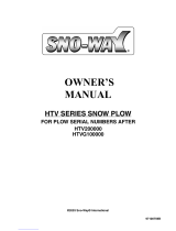
Key:
A: Filler Hole & Relief Valve
B: “B” Solenoid (Red)
C: Left Angle Cylinder Connection
D: Right Angle Cylinder Connection
E: “C” Solenoid (Green)
F: “A” Solenoid (Black)
G: Crossover Relief Valve
H: Lift Cylinder Connection
I: “B” Check Valve
J: Drain Plug
K: Motor Solenoid
L: Drop Speed Adjustment
A F
E
D
B
G
H
I
C
J
K
L
E-73 HYDRAULIC COMPONENT IDENTIFICATION

14
9 / 10 / 12 / 13 / 14 / 16 / 17 / 18
!
!
DANGER
!
WARNING
!
CAUTION
CAUTION
!
!
DANGER
!
WARNING
!
CAUTION
CAUTION
!
!
DANGER
!
WARNING
!
CAUTION
CAUTION
21 / 28
!
!
DANGER
!
WARNING
!
CAUTION
CAUTION
SAFETY PRECAUTIONS -
See pages 2-3 for denitions
Before any troubleshooting is started, make certain the following conditions are met.
1. The moldboard is pointing straight ahead. If the unit is disabled, this can often be done by connecting the
hose from the left cylinder into the right cylinder and pushing the snow plow by hand.
2. Check to ensure the power angling cylinders are installed correctly.
3. The solenoid coils must be on their proper valve: the “C”- coil (green and white wire), the “B”-coil (red and
white wire) and the “A” coil (black and white wire).
4. The electrical installation must have been made according to installation instructions supplied by
Meyer Products LLC.
TESTING
Many tests do not require removing the Power Unit from the vehicle. However, more thorough testing can be
done by using the Meyer Test Stand (available at Authorized Servicing Dealers) which allows direct pressure
and Amperage readings.
1. Use a screwdriver or other small tool to check for magnetism of solenoid coils “A”, “B” & “C”.
Place the tool on the side of the coil and have an assistant operate the switch. You should feel magnetic attraction.
2. Use a test light or volt meter to determine whether there is power at harness or switches. (The wire must
be probed)
3. When determining Amp draw of motor, always obtain the highest value possible, i.e., at maximum raise
or angle with motor running.
4. Proper rotation for motor is indicated by an arrow on the top of the pump.
5. The pump shaft (all models) of a good pump can be turned smoothly using two ngers. If it cannot be
turned easily, the pump is too tight and must be replaced.
6. Pump pressure can be measured at an angle hose (note pressure at full angle) or in the pressure lter port
(an adapter is necessary for the lter port).
7. If hydraulic system is contaminated with oil or a substance other than Meyer Hydraulic Fluid, it is recommended
that the hydraulic unit, power angling rams and hoses be drained and ushed clean with Meyer M-2 Flush Fluid.
The system should then be relled with Meyer M-1 Fluid.
Raise Lower
Angle
Right
Angle
Left
MOTOR X X X MOTOR
A X A
B X B
C X C
E-73 Hydraulics – Testing Tips

15
CONDITION POSSIBLE CAUSE CORRECTION
Plow does not lift or
lifts slowly - motor
operates
1. Low hydraulic uid level.
2. Discharged battery.
3. Leaking or open “A” cartridge.
4. No current to “B” coil. (red and white or black wire)
5. Inoperative “B” coil. (red and white or black wire)
6. Malfunctioning motor.
7. Malfunctioning pump.
1. Add uid to proper level
2. Recharge battery.
3. Clean or replace “A” cartridge.
4. Locate malfunction and repair.
5. Replace “B” coil. (red and white or black wire)
6. Repair or replace motor.
7. Replace pump.
Plow does not angle
right - motor operates
1. Improper coupler arrangement.
2. Mechanical bind or interference.
3. Malfunctioning coupler. (if equipped)
4. No current to “C” coil. (green and white or black wire)
5. Inoperative “C” coil. (green and white or black wire)
6. Inoperative “C” cartridge.
7. Leaking crossover relief valve.
1. Engage coupler properly.
2. Eliminate mechanical bind or interference.
3. Repair or replace coupler.
4. Locate malfunction and repair.
5. Replace “C” coil. (green and white or black wire)
6. Clean or replace “C” cartridge.
7. Replace crossover relief valve.
Plow does not angle
left - motor operates
1. Improper coupler arrangement.
2. Mechanical bind or interference.
3. Malfunctioning coupler. (if equipped)
4. Leaking crossover relief valve.
1. Engage coupler properly.
2. Eliminate mechanical bind or interference.
3. Repair or replace coupler.
4. Replace crossover relief valve.
Plow does not angle -
motor operates
1. Improper coupler arrangement.
2. Mechanical bind or interference.
3. Leaking crossover relief valve.
1. Engage coupler properly.
2. Eliminate mechanical bind or interference.
3. Replace crossover relief valve.
These charts are intended to be used as an aid in diagnosing Meyer Hydraulic Power Units. They are not a
substitute for factory training and experience. Be certain to read the General Information and Testing Tips
sections before attempting any troubleshooting. Additional detailed information as well as all electrical
schematics may be found in Service Manuals @ www.MeyerProducts.com.
For questions please contact www.meyerproducts.com, or call 216-486-1313.
9 / 10 / 12 / 13 / 14 / 16 / 17 / 18
!
!
DANGER
!
WARNING
!
CAUTION
CAUTION
!
!
DANGER
!
WARNING
!
CAUTION
CAUTION
!
!
DANGER
!
WARNING
!
CAUTION
CAUTION
21 / 28
!
!
DANGER
!
WARNING
!
CAUTION
CAUTION
SAFETY PRECAUTIONS -
See pages 2-3 for denitions
E-73 Hydraulics
Troubleshooting Guide

16
CONDITION POSSIBLE CAUSE CORRECTION
Plow will not hold in
angled position
1. Air in cylinders and hoses.
2. Leaking dual pilot check valve.
3. Leaking crossover relief valve.
4. Crossover relief valve opening at too low
a pressure.
1. Bleed cylinders and hoses.
2. Replace pilot check valve.
3. Replace crossover relief valve.
4. Replace crossover relief valve.
Motor does not operate
1. Discharged or defective battery.
2. Loose/corroded electrical connections.
3. Inoperative starter solenoid.
4. Malfunctioning control switch.
5. Malfunctioning motor.
1. Recharge or replace battery.
2. Clean and tighten electrical connections.
3. Replace starter solenoid.
4. Replace control switch.
5. Repair or replace motor.
Plow does not lower
1. No current to “A” coil.
(black and white or black wire)
2. “A” cartridge jammed in closed position.
3. Inoperative “A” coil.
(black and white or black wire)
1. Locate malfunction and repair.
2. Clean or replace “A” cartridge.
3. Replace “A” coil.
(black and white or black wire)
Plow creeps down
1. Leaking “A” cartridge.
2. Leaking “A” cartridge O-ring.
3. Leaking “B” check valve.
4. Leaking Ram Packing Cup.
5. Leaking O-ring at bottom of lift cylinder.
1. Clean or replace “A” cartridge.
2. Replace O-ring.
3. Clean or replace “B” check valve.
4. Replace Ram Packing Cup.
5. Replace O-ring.
These charts are intended to be used as an aid in diagnosing Meyer Hydraulic Power Units. They are not a
substitute for factory training and experience. Be certain to read the General Information and Testing Tips
sections before attempting any troubleshooting. Additional detailed information as well as all electrical
schematics may be found @ www.MeyerProducts.com.
For questions please contact www.meyerproducts.com, or call 216-486-1313.
2 / 9 / 10 / 12 / 13 / 14 / 16 / 17 / 18
!
!
DANGER
!
WARNING
!
CAUTION
CAUTION
!
!
DANGER
!
WARNING
!
CAUTION
CAUTION
!
!
DANGER
!
WARNING
!
CAUTION
CAUTION
28
!
!
DANGER
!
WARNING
!
CAUTION
CAUTION
SAFETY PRECAUTIONS -
See pages 2-3 for denitions
E-73 Hydraulics Troubleshooting Guide
/