Page is loading ...

CONTRACTOR: Read these instructions before install-
ing or servicing humidifier.
HOMEOWNER: Save this manual for future reference.
Model No.
Mfg. Date (see label on unit)
Installation Date:
READ AND SAVE THESE INSTRUCTIONS
Installation Instructions* for
Model 60-Series High-Capacity
Steam Humidifiers
(Models 60-1, F60-1, 60-2 and F60-2)
Includes:
Warranty Information
Programmable Flushing Timer
Installation Instructions
Operating and Maintenance
Instructions
*See “Wiring Instructions for High-Capacity Steam Humidifiers” separately

2
Table of Contents
Page
Thank You! ....................................................................................................... 3
Warranty Validation Notice (Important. Please read.)...................................... 3
Skuttle Limited One-Year Product Warranty.................................................... 4
CONTRACTOR:
How To Install a Skuttle Model 60-Series Steam Humidifier............................ 6
• Safety Precautions..................................................................................... 6
• Tools & Materials Needed.......................................................................... 7
Selecting a Location......................................................................................... 7
Mounting the Humidifier (Options A-C) ............................................................ 8
Plumbing and Setting the Water Level........................................................... 11
How to Install the Programmable Automatic Flushing Timer......................... 13
• To Reprogram the Automatic Flushing Timer.......................................... 15
How To Maintain a Skuttle Steam Humidifier................................................. 16
Trouble Shooting............................................................................................ 17
Replacement Parts......................................................................................... 18
HOMEOWNER:
How Your Humidifier Works ........................................................................... 21
How To Extend the Life of Your Humidifier.................................................... 22
FAQs About IAQ............................................................................................. 23
Contact Information.................................................................... 24
(Back Cover)

3
Thank you for purchasing a Skuttle whole-house Steam Humidifier. We
appreciate your business and consider you a valued customer. We sincerely
hope you are satisfied with our product and its performance.
Skuttle is the oldest manufacturer of residential humidifiers, having been in
business since 1917. Our longevity and dedication to our customers has
resulted in products that are unsurpassed in quality and ease of operation.
Features such as automatic controls, high-quality materials and superior work-
manship make this Skuttle Steam Humidifier a valuable enhancement to your
home’s HVAC system. In addition to humidifiers, we manufacture air filters,
make-up air controls and indoor air quality (IAQ) accessories to improve the
comfort and healthfulness of your home.
As always, quality, performance and customer satisfaction are our highest
priorities. The information contained in this manual will aid you and your
HVAC contractor with the installation and periodic maintenance necessary to
keep your humidifier operating at peak efficiency. If, at some point, you need
parts or service, follow these simple procedures:
• First, try calling the heating and air conditioning dealer who installed your
humidifier. This information may be located on the back of this booklet, or
the dealer may have placed a reference label on your heating system.
• If you cannot locate your original installer, check the Internet or the Yellow
Pages under “Heating & Air Conditioning Contractors” for an alternative
dealer.
• If these attempts fail, email Skuttle Indoor Air Quality Products at
[email protected], or call us toll-free at (800) 848-9786. We’ll
be glad to assist you.
For further information regarding the benefits, operation and maintenance of
your new Skuttle Steam Humidifier, refer to the applicable sections of this
manual.
Important: WARRANTY VALIDATION
The completion and return of the Warranty Registration Card (enclosed
separately in your Skuttle humidifier carton) is required for warranty
coverage.
The warranty described herein is not valid unless the Warranty Card is
completed and mailed to Skuttle Manufacturing Company within 15 days of
equipment installation.

4
Skuttle
®
Limited One-Year* Product Warranty
This limited one-year warranty covers this Skuttle product as designated on
the return portion of the Warranty Registration Card, excluding wiring, plumb-
ing and installation.
*NOTE
: The 120 volt heater (Part No. 000-0430-055) and the 240 volt
heater (Part No. 000-0430-056) are covered by a limited two-year warranty.
All other aspects of this warranty, as stated below, apply.
Skuttle Manufacturing Company warrants that this product is free from defects
in material and workmanship under normal, noncommercial use and service.
Skuttle will remedy any such defects if they appear within 12 months from the
date of the original installation, as evidenced by receipt of the Warranty Regis-
tration Card, subject to the terms and conditions of this limited one-year
warranty, stated below:
1. THIS LIMITED ONE-YEAR WARRANTY IS GRANTED BY SKUTTLE
MFG. CO., 101 Margaret Street, Marietta, OH 45750.
2. This warranty shall extend only to any noncommercial owner who has pur-
chased this residential product other than for purposes of resale.
3. The completion and return of the Warranty Registration Card is a condi-
tion precedent to warranty coverage and performance. Warranty is not
valid unless this card is completed and mailed to the factory within fifteen
(15) days of equipment installation.
4. All components are covered by this limited warranty, except expendable
items.
5. If, within the warranty period, this product or any component requires ser-
vice, it must be performed by a competent heating and/or plumbing con-
tractor (preferably the installing contractor). Skuttle will not pay shipping or
labor charges to remove or replace such defective parts or components. If
the part or component is found by inspection to contain such defective
material and/or workmanship, it will either be repaired or exchanged, free
of charge, at Skuttle’s option, and returned by prepaid freight.
6. In order to obtain the benefits of this limited one-year warranty, the owner
must notify the dealer or distributor in writing of any defects within thirty
(30) days of the discovery. If after reasonable time, the owner has not re-
ceived an adequate response from the dealer or distributor, he/she should
notify in writing: Skuttle Manufacturing Company, 101 Margaret Street,
Marietta, OH 45750. (SKUTTLE WILL RECEIVE, FREIGHT PREPAID,
ONLY REMOVABLE PARTS OR COMPONENTS OF SUCH DEFECTIVE
PRODUCTS.)

5
7. This limited warranty does not apply to any part or component that is: dam-
aged in transit or handling; has been subject to abuse, neglect or accident;
has not been installed, operated and serviced according to Skuttle’s in-
structions; has been operated beyond the factory-rated capacity; or has
been altered in any such way that its performance is affected. There is no
warranty due to neglect, alteration or ordinary wear and tear. Skuttle’s
liability is limited to replacement of defective parts or components, and
does not include the payment of the cost of labor charges to remove or
replace such defective components or parts.
8. Skuttle will not be responsible for loss of use by any product, loss of time,
inconvenience or any other indirect, incidental or consequential damages
with respect to person or property, whether as a result of breach of con-
tract, neglect or otherwise. (SOME STATES DO NOT ALLOW THE EX-
CLUSION OR LIMITATION OF INCIDENTAL OR CONSEQUENTIAL
DAMAGES, SO THE LIMITATION OF EXCLUSION IN THE PRECEDING
SENTENCE MAY NOT APPLY TO YOU.)
9. THE WARRANTY GIVES THE OWNER SPECIFIC RIGHTS, AND YOU
MAY ALSO HAVE OTHER RIGHTS WHICH VARY FROM STATE TO
STATE.
10. Any warranty work will be performed within a reasonable time, usually
within one-hundred-twenty (120) days after notice of defect and delivery to
the Skuttle factory, subject to delays beyond the manufacturer’s control.
11. Any warranty by Skuttle of merchantability, fitness for use or any other
warranty (express, implied or statutory), representation or guarantee other
than what was set forth herein, shall expire at the expiration date of this
limited warranty. (SOME STATES DO NOT ALLOW LIMITATION OF
HOW LONG AN IMPLIED WARRANTY LASTS, SO THE LIMITATION IN
THE PRECEDING SENTENCE MAY NOT APPLY TO YOU.)
12. Skuttle reserves the right to make changes in the design and material of
its products without incurring any obligation to incorporate such changes
in the units completed prior to the effective date of such change.

6
For the Contractor: How To Install
a Skuttle Model 60-Series Steam Humidifier
NOTES: This humidifier must be installed by a qualified professional
contractor. Failure to comply with this requirement may nullify the
warranty.
Read all instructions before beginning installation of the humidifier.
Skuttle Manufacturing Company assumes no responsibility under warranty if
the contractor and user do not follow these printed instructions.
FOR WIRING INSTRUCTIONS AND INSTALLATION OF THE ELECTRONIC
COMPENSATING HUMIDISTAT, PLEASE SEE SEPARATE INSTRUC-
TIONS ENCLOSED IN THE HUMIDIFIER CARTON.
Safety Precautions
1. Do not install a humidifier where the surrounding temperature may exceed
200°F.
CAUTION
: Excessive heat will damage the humidifier, possibly causing
an overflow condition and water damage to the home.
2. Do not install a humidifier where the surrounding temperature may be
32°F or colder (e.g., attics, garages, etc.).
CAUTION
: Freezing water will damage the humidifier and burst the sup-
ply pipe, resulting in damage to the home.
3. Do not cut or drill into any air conditioning components or electrical enclo-
sures during humidifier installation.
DANGER
: Electrocution is possible if you come in contact with a
live electrical wire; blindness can occur if refrigerant contacts your
eyes.
4. When the humidifier is installed in a finished basement or any area where
water damage could occur, be sure to connect the humidifier’s overflow
provision to a suitable drain.
5. For above-ceiling installations, install an additional drain pan plumbed to a
suitable drain.
6. Installation, wiring and plumbing of the humidifier must comply with local
codes, ordinances and regulations.

7
Tools and Materials Needed
1. Safety goggles
2. Tin snips or aviation snips
3. Electric drill
4. 3/8" and 7/64" drill bits
5. Pliers
6. Screwdrivers (medium flat point and Phillips #1)
7. Level
8. Hammer
9. Small adjustable wrench
10. Center punch
11. Knife
12. Wire and hardware to connect fan control
13. Additional relay(s)
For some installations:
14. Duct tape
15. 1/4" copper water line
16. Tubing and fittings for the overflow connection
17. 2 conductor low-voltage wire
Selecting a Location
1. For most installations, mount the humidifier under the horizontal warm air
supply duct. As an alternative, the unit can be mounted on a vertical
plenum using a fabricated transition for support. (See “Mounting the
Humidifier”, pgs. 8-10.)
NOTE
: Ideally, the Skuttle Steam Humidifier is not intended for installa-
tion in or on the return air duct or plenum. However, some contractors do
so without complications. If you choose to install a Skuttle Model 60
Humidifier under a return air duct or on a return air plenum, be aware
that moisture MUST be absorbed BEFORE entering the filter, blower,
turn or transition. Therefore, INSTALL THE HUMIDIFIER AT LEAST
4-TO-6 FEET PRIOR TO THESE DEVICES AND CONFIGURATIONS.
2. Select a location where the humidifier can be plugged in without the use
of an extension cord. (See separate manual, “Wiring Instructions for High-
Capacity Steam Humidifiers”.)
3. Select a location that will not allow steam to condense on the system air
mover, electrical components, etc.
4. Mount the unit on rigid metal ductwork, never on duct board or internally-
insulated duct.

8
Figure 1—Option A:
Duct Edge Mount
CAUTION
: For all installation configurations, the mounting area
must be strong enough to support the humidifier’s weight when it is
full of water (approximately 18 lbs.), and to hold the humidifier in a level
position for safe, reliable operation. Otherwise, additional duct reinforce-
ment will be necessary.
NOTE
: If the installation includes exposed insulated materials, a section
of the ductwork must be removed and replaced with rigid metal duct ex-
tending at least 6 feet downstream from the humidifier.
5. Mount the unit at least 4-to-6 feet after the plenum transition. Avoid
sudden turns or transitions in the ductwork in the immediate area down-
stream from the humidifier.
Mounting the Humidifier
Option A is the preferred method of
mounting because it requires the least
amount of duct reinforcement to support
the humidifier and keep it level. A duct
width of at least 10 inches is necessary.
Wider ducts may need to be reinforced in
order to hold the humidifier level.
DANGER
: Wear safety glasses when
cutting or drilling. Do not cut or drill into
any air conditioning components or electri-
cal enclosures during installation. Electro-
cution is possible if you come in con-
tact with a live electrical wire; blind-
ness can occur if refrigerant contacts
your eyes.
To install (Option A):
1. Place the mounting bracket (provided)
on the edge of the ductwork where the
humidifier is to be installed.
2. Use a marker to trace around the inside of the mounting bracket. Cut out
the duct opening.
CAUTION
: DO NOT attach the mounting bracket before the hole in the
ductwork has been cut.
3. Attach the mounting bracket to the ductwork with sheet metal screws.
Figure 2—Mounting Bracket

9
4. Attach the L-shaped bracket to the top/front of the humidifier, so that the
vertical wall is toward the reservoir.
5. Adjust the water level. (See Nos. 7 & 8 in “Plumbing and Setting the Water
Level”, pgs. 11 & 12.)
6. Slide the flanges of the humidifier reservoir into the mounting bracket until
the reservoir’s front flange comes in contact with the edge of the duct.
7. Secure the humidifier to the duct with the screws provided.
Option B requires a transition to be
made, and usually needs duct reinforce-
ment to hold the humidifier securely in
place.
NOTE
: For this configuration, the humidi-
fier is mounted on the outside of the
plenum, rather than the inside, so as not
to restrict airflow.
DANGER
: Wear safety glasses when
cutting or drilling. Do not cut or drill into
any air conditioning components or electri-
cal enclosures during installation. Elec-
trocution is possible if you come in
contact with a live electrical wire; blind-
ness can occur if refrigerant contacts
your eyes.
To install (Option B):
1. Construct a transition and attach it to
the plenum. (Additional humidifier sup-
port will be necessary for this configu-
ration.)
2. Place the mounting bracket (provided) at the base of the transition.
3. Use a marker to trace around the inside of the mounting bracket. Cut out
the duct opening.
CAUTION
: DO NOT attach the mounting bracket before the hole in the
ductwork has been cut.
4. Attach the L-shaped bracket to the top/front of the humidifier, so that the
vertical wall is toward the reservoir.
Figure 3—Option B:
External Side Mount
Figure 4—Mounting Bracket

10
5. Adjust the water level. (See Nos. 7 & 8 in “Plumbing and Setting the Water
Level”, pgs. 11 & 12.)
6. Slide the flanges of the humidifier reservoir into the mounting bracket.
7. Secure the humidifier to the duct with the screws provided.
Option C requires duct reinforcement
to hold the humidifier securely in place.
DANGER
: Wear safety glasses when
cutting or drilling. Do not cut or drill into
any air conditioning components or electri-
cal enclosures during installation. Electro-
cution is possible if you come in con-
tact with a live electrical wire; blind-
ness can occur if refrigerant contacts
your eyes.
To install (Option C:)
1. Place the mounting bracket (provided)
at the selected location on the bottom
of the duct.
2. Use a marker to trace around the in-
side of the mounting bracket. Cut out
the duct opening.
CAUTION
: DO NOT attach the
mounting bracket before the hole in the
ductwork has been cut.
3. Attach the mounting bracket to the ductwork with sheet metal screws.
4. Adjust the water level. (See Nos. 7 & 8 in “Plumbing and Setting the Water
Level”, pgs. 11 & 12.)
5. Slide the flanges of the humidifier reservoir into the mounting bracket.
6. Secure the humidifier to the duct with the screws provided.
NOTE
: See separate wiring instruction manual, “Wiring Instructions for High-
Capacity Steam Humidifiers”.
Figure 5—Option C:
Duct Center Mount
Figure 6—Mounting Bracket

11
Plumbing and Setting the Water Level
NOTE
: Use copper tubing only to plumb this humidifier.
1. Select the nearest cold water pipe and install the saddle connector and
needle valve (provided) by following the instructions supplied with the
valve.
WARNING
: Do not use any line connected to an air conditioner.
2. Lightly clean the tubing ends with fine sandpaper before making connections.
3. Uncoil the copper tubing and
connect one end to the saddle
valve. Use the compression fit-
tings found in the self-piercing
saddle valve parts bag.
• Place the brass compression
nut over the tubing, then slide
the brass ferrule over the
tubing.
• Fully insert the tubing into
the saddle valve fitting and
tighten the compression nut.
(Do not over-tighten; moderate tightness should prevent leaking.)
• Thoroughly flush the supply tubing after attaching it to the saddle
valve. This will clear the line of debris which could block water flow at
the float valve.
4. Route the tubing to the humidifier float valve, keeping the tubing away
from sharp edges.
5. Connect the remaining end of the tubing to the humidifier float valve.
6. Open the saddle valve so that the water flows slowly and gently into the
water pan.
7. Prior to mounting, adjust the humidifier’s water level by following these
instructions:
• Set the humidifier reservoir on a level surface.
• Allow the unit to fill until the float valve shuts off the incoming flow of
water. (The water should be 2-3/8" deep, plus or minus 1/8". If it is not,
further adjustment will be necessary.)

12
Figure 7-A—Raising the
water level
Figure 7-B—Lowering the
water level
8. If the water level is too high, remove enough water from the reservoir to
allow the float valve to automatically fill and shut off the water. This will
verify that your final adjustment is correct.
9. Shut off the water supply and remove all water from the reservoir.
10. Mount the humidifier according to Options A, B or C, shown on pages 8-10.
11. Check the two compression fittings—one at the saddle valve, the other at
the float valve. Stop any leakage by tightening the fittings.
12. Connect the humidifier’s overflow provision to a suitable waste drain.
• A standard garden hose or a 3/8" N.P.T. male fitting (not supplied) can
be attached to the overflow fitting.
• Provide support at many points along the hose to prevent kinks—
particularly near any heat source.
13. Turn the water to the humidifier on. The float valve should shut the water
off when the pan is filled to 2-3/8".
14. Make sure the humidifier is plugged into a powered outlet.
15. Adjust the compensating humidistat according to instructions provided with
the unit.
CAUTION
: To prevent valve seat damage, never adjust the humidi-
fier’s water level without supporting the float arm. Make adjustments
in small increments.
• To raise the water level, push down in the center of the float arm (see
Figure 7-A, below).
• To lower the water level, hold the float on the bottom of the reservoir
with one hand and pull up on the center of the float arm with the other
hand (see Figure 7-B, below).

13
How To Install the
Programmable
Automatic Flushing Timer
The Humidifier Automatic Flushing Timer
automatically flushes accumulated min-
eral deposits from all central-system
steam– and reservoir-type humidifiers.
This enables homeowners to enjoy the
benefits of healthful, humidified air with-
out the hassles of frequent maintenance
due to mineral buildup.
The flushing timer is set at the factory to
flush the humidifier every two hours for a
duration of 10 seconds, using only about
1.5 gallons of water per day. (See
“Reprogramming Instructions”, page 15, for alternate settings.) This flushing
reduces or eliminates servicing during the humidification season, depending
on the mineral content of the water.
To Install the Flushing Timer on a Steam Humidifier:
Figure 8—Installation of a
Programmable Automatic
Flushing Timer on a Steam
Humidifier
CAUTION
: All plumbing
and electrical connections
must comply with relevant
codes and ordinances.

14
1. If the humidifier has been preinstalled and needs servicing, refer to “How
to Maintain a Skuttle Steam Humidifier” (page 16) for instructions.
2. For either a new or preinstalled humidifier, select a suitable mounting
location for the flushing timer within 3 feet of the humidifier, and within 10
feet of a properly fused electrical outlet.
3. Locate a suitable waste drain for disposal of flushed water.
CAUTION
: Drain tubing must not kink or come in contact with
sharp edges or hot surfaces. Tubing must run in a continual downhill
slope to allow proper drainage and to prevent overflow.
4a. If this flushing timer was purchased as an accessory to install on a
steam humidifier… remove the drain valve from the humidifier and install
the 90º barbed fitting (provided), as shown in Figure 8 (page 13).
4b. If this flushing timer was purchased with the steam humidifier as a
complete assembly… the 90º barbed fitting should already be installed
on the humidifier in the proper location. (See Figure 8, page 13.)
5. Screw the unit to the mounting surface selected in Step #2.
6. Cut a piece of drain tubing to reach from the humidifier fitting to the fitting
on the side of the flushing timer.
CAUTION
: Drain tubing must not kink or come in contact with
sharp edges or hot surfaces. (This caution applies to Step #7, as well.)
7. Cut a second piece of tubing to reach from the bottom fitting on the flush-
ing timer to the drain. (See Step #3.)
8. Connect tubing with clamps or fittings suitable for your installation.
9. Return the steam humidifier to its normal operating mode. Refer to pages
11 & 12 to properly set the water level.
10. Plug the flushing timer into the designated outlet. (See Step #2.)
11. Check all fittings for leaks. Tighten as necessary.
12. Test the flushing timer for proper operation.
A. Press and release the MANUAL button.
B. Wait 10 to 30 seconds* until the flushing noise stops, indicating that
the flushing cycle is complete.
*The number of seconds will vary depending upon how the unit is pro-
grammed. (See “Reprogramming Instructions”, page 15.)

15
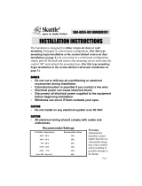
To Reprogram the Automatic Flushing Timer:
The flushing timer is set at the factory to flush the humidifier every two hours for
a duration of 10 seconds, using approximately 1.5 gallons of water per day.
Although the two-hour intervals between flushes may not be altered, the dura-
tion may be lengthened to either 20 or 30 seconds per flush.
1. Unplug the flushing timer from the electrical outlet.
2. Take off the back cover plate by removing the three screws closest to the
moutning flanges.
3. Inside, on the circuit board, locate the red switch block which contains two
switches, numbered 1 and 2.
NOTE
: The switches are pre-set in the 10-second mode, with
the #1 switch in the ON position, and the #2 switch in the OFF
position, as shown at right.
4. To reprogram the flushing timer to 20-second flushes
every 2 hours, move the #1 switch to the OFF position, and
the #2 switch to the ON position, as shown at left. At this
setting, the automatic flushing timer will use approximately 3
gallons of water per day.
5. To reprogram the flushing timer to 30-second flushes every
2 hours, move both switches to the OFF position, as shown at
right. At this setting, the automatic flushing timer will use
approximately 4.5 gallons of water per day.
6. Reposition the back cover plate on the flushing timer and secure it with
the three screws.
7. Plug the flushing timer back into the wall outlet. Make sure it is functioning
properly with the humidifier. (See Step #12, page 14.)
NOTE
: Lengthening the flushing duration will help keep the humidifier
cleaner. However, it may also cause undesirable drain noise.

16
How To Maintain
a Skuttle Steam Humidifier
Because the Skuttle Steam Humidifier is designed to emit mineral-free mois-
ture into the air, the unit should be cleaned and serviced every two-to-four
months during the humidification season. Harder water, colder weather and/or
higher humidistat settings will increase the frequency of cleaning and service.
NOTE
: Some 60-series units (Models F60-1 and F60-2) are equipped with a
Skuttle Automatic Flushing Timer (see page 22), which can reduce mainte-
nance significantly. However, it is still wise for the homeowner to check the
humidifier for mineral buildup every two months or so.
To perform routine maintenance tasks, follow these instructions:
WARNING: Do not touch the humidifier when the operation indicator
light is on. Always unplug the unit and allow it to cool prior to service or
inspection.
1. Unplug the humidifier and fan control; disconnect the humidistat wires
from the external screw terminals.
2. Turn off the water supply and disconnect the supply tubing at the float
valve. Disconnect the overflow hose at the humidifier.
3. Allow water in the humidifier to cool before continuing.
WARNING: Scalding is possible if water in the humidifier reservoir
has not been allowed to cool.
4a. For steam humidifier Models 60-1 or 60-2 (without an automatic flush-
ing timer), turn the petcock (drain fitting) counterclockwise (4) and drain
water from the humidifier into a bucket.
4b. For steam humidifier Models F60-1 and F60-2, use the automatic flush-
ing timer to drain the unit by following these instructions:
A. Press and release the MANUAL button on the flushing timer.
B. Wait 10 to 30 seconds until the flushing noise stops, indicating that
the flushing cycle is complete. (The number of seconds will vary
depending upon how the timer is programmed.)
C. Repeat Steps A and B until the humidifier is drained.
5. Remove the humidifier from its mounting.
6. Flush loose minerals from the reservoir with water, then gently rub miner-
als off the float, heater, reservoir walls and safety float switch. If mineral
deposits

17
Trouble Shooting
PROBLEM EVIDENCE SOLUTION(S)
Low Humidity Low water level (less than • See Plumbing and Setting Water Level,
2-3/8" deep) steps 7 & 8
No water in reservoir • Turn water on at saddle valve
• Turn off water main and check for possi-
ble obstruction in saddle valve or float
valve
Humidifier heater is not • Make sure the humidifier is plugged in
operating • Set the humidistat higher
• Check for blown circuit breaker
• Check all external wiring connections
• Check for low water level
• Check the humidistat switch for continuity
• Call a professional HVAC contractor
Rapid air changes (drafts) • Keep doors and windows closed (cold, dry
air is an added load on the humidifier)
• Close fireplace damper when not in use
• Keep exhaust fan running time to a mini-
mum
• Seal around doors and windows
continued...
deposits have been allowed to build up, steel wool or other scouring pads
may be used.
7. Inspect the valve arm and float for mineral buildup and deterioration.
CAUTION
: If deterioration is noted, replacement will be necessary.
8. Reset the water level. (See Steps 7 & 8 of “Plumbing and Setting the
Water Level”, pgs. 11 & 12.)
9. Remount the humidifier and make all electrical and plumbing reconnec-
tions. Check for leaks or overflow. Set the humidistat as directed in the
humidistat instructions.
CAUTION
: Never oil any part of the humidifier.
NOTE
: At the end of each humidification season (approximately the
same period as the heating season), the humidifier should be thor-
oughly cleaned and the water and electricity turned off until the next
humidifying season.
CAUTION
: Do not leave water in the humidifier over the warm-
weather months.

18
PROBLEM EVIDENCE SOLUTION(S)
High Humidity Condensation on walls • Turn humidistat off
• Turn water to humidifier off until conden-
sation is evaporated
Heavy condensation on • Turn humidistat down enough to eliminate
windows condensation (this may be a temporary
condition caused by moisture from bath-
ing, mopping, cooking, etc.)
Humidifier High water level • Inspect valve seat for defects
Overflows • Inspect valve nozzle for cracks or erosion
• Readjust water level (see Plumbing and
Setting Water Level, steps 7 & 8)
• Make sure humidifier is level
Table 1
Trouble Shooting (cont’d.)
Replacement Parts
Contractors: Parts may be ordered through your preferred heating or plumb-
ing distributor. When ordering, refer to the appropriate parts list, beginning on
page 19, to give the following information:
• Humidifier Model Number • Part Name • Part Number
• Humidifier Manufacturing Date (see label on side near drains)

19
Parts for Models 60-1, F60-1, 60-2 and F60-2
Item Part Name Part No.
1* 120 Volt Heater 000-0430-055
1** 240 Volt Heater 000-0430-056
2 Safety Float Switch 000-0814-132
3 Float for Water Fill Valve A00-1309-012
4 Water Fill Valve 000-1731-012
5 Water Pan Assembly A01-1730-078
6 Cover 000-0641-150
7* Transformer 120 Volt Primary 24 Volt Secondary 000-0814-133
7** Transformer 240 Volt Primary 24 Volt Secondary 000-0814-140
8 Control Relay DPST 24 Volt 000-0431-031
9 & 10 Fan Wiring Assembly A00-0811-120
*Models 60-1 and F60-1 only **Models 60-2 and F60-2 only continued...
Figure 9—Parts Diagram of Models 60-1, F60-1, 60-2 and F60-2

20
Parts for Models 60-1, F60-1, 60-2 and F60-2, cont’d.
Item Part Name Part No.
11 Humidistat Control Terminal Block 000-0814-135
12 Indicator Light 000-0814-139
13 Thermal Fan Control “Thermostat” 000-0431-030
14 Power Distribution Terminal Block 000-0814-134
15* 120 Volt Power Supply Cord 000-0811-107
15** 240 Volt Power Supply Cord 000-0811-108
16 Saddle Valve A00-1128-005
17 Compustat Assembly SEH-7100-000
18 Drain Cock Valve 000-1319-065
19 Drain and Overflow Bushing
(w/Overflow Bushing, Washer & Lock Nut) A00-1319-067
20 90º Barbed Elbow 000-1106-034
Not 9 pc. Gasket Set
(w/Drain, Overflow, Thermostat, Safety Float A00-0693-020
Shown
and Heater Washers)
Table 2
NOTES
: A Skuttle Automatic Flushing Timer (Model S-HAFT) is included
with Steam Humidifiers F60-1 and F60-2.
Due to Skuttle’s ongoing research and development program, specifications
are subject to change without notice.
/