Bosch GLL 3-50 Owner's manual

Category
Rangefinders
Type
Owner's manual

This manual is also suitable for

3 |
1 618 C00 99J | (10.10.13) Bosch Power Tools
F
E
D
C
B
A
OBJ_BUCH-1973-002.book Page 3 Thursday, October 10, 2013 4:45 PM
1 618 C00 99J | (10.10.13) Bosch Power Tools
4 |
30 mm
23
25
22
26
24
2 607 002 195
0 601 096 974
2 607 990 031
0 601 015 B00
0 601 015 A00
0 601 069 100
27
1 608 M00 05A
28
L-BOXX 136
1 605 438 166
29
I
H
G
OBJ_BUCH-1973-002.book Page 4 Thursday, October 10, 2013 4:45 PM
5 |
1 618 C00 99J | (10.10.13) Bosch Power Tools
1
16
17
17
1
1
3
2
4
5
1
6
7
8
14
17
11
15
18
10
9
13
12
19
20
20
21
OBJ_BUCH-1973-002.book Page 5 Thursday, October 10, 2013 4:45 PM
12 | English
1 618 C00 99J | (11.10.13) Bosch Power Tools
Österreich
Tel.: (01) 797222010
Fax: (01) 797222011
Schweiz
Tel.: (044) 8471511
Fax: (044) 8471551
E-Mail: Aftersales.S[email protected]
Luxemburg
Tel.: +32 2 588 0589
Fax: +32 2 588 0595
Entsorgung
Messwerkzeuge, Zubehör und Verpackungen sollen einer um-
weltgerechten Wiederverwertung zugeführt werden.
Werfen Sie Messwerkzeuge und Akkus/Batterien nicht in den
Hausmüll!
Nur für EU-Länder:
Gemäß der europäischen Richtlinie
2012/19/EU müssen nicht mehr ge-
brauchsfähige Messwerkzeuge und gemäß
der europäischen Richtlinie 2006/66/EG
müssen defekte oder verbrauchte Akkus/
Batterien getrennt gesammelt und einer
umweltgerechten Wiederverwendung zu-
geführt werden.
Akkus/Batterien:
Werfen Sie Akkus/Batterien nicht in den Hausmüll, ins Feuer
oder ins Wasser. Akkus/Batterien sollen, wenn möglich entla-
den, gesammelt, recycelt oder auf umweltfreundliche Weise
entsorgt werden.
Nicht mehr gebrauchsfähige Akkus/Batterien können direkt
abgegeben werden bei:
Deutschland
Recyclingzentrum Elektrowerkzeuge
Osteroder Landstraße 3
37589 Kalefeld
Schweiz
Batrec AG
3752 Wimmis BE
Änderungen vorbehalten.
English
Safety Notes
Working safely with the measuring tool is
possible only when the operating and safety
information is read completely and the in-
structions contained therein are strictly fol-
lowed. Never make warning labels on the
measuring tool unrecognisable. SAVE
THESE INSTRUCTIONS.
Caution – The use of other operating or adjusting
equipment or the application of other processing meth-
ods than those mentioned here can lead to dangerous
radiation exposure.
The measuring tool is delivered with a warning label in
English language (marked with the number 12 in the
representation of the measuring tool on the graphic
page).
Do not direct the laser beam at persons
or animals and do not stare into the laser
beam yourself. This measuring tool pro-
duces laser class 2 laser radiation accord-
ing to IEC 60825-1. This can lead to per-
sons being blinded.
Do not use the laser viewing glasses as safety goggles.
The laser viewing glasses are used for improved visualisa-
tion of the laser beam, but they do not protect against laser
radiation.
Do not use the laser viewing glasses as sun glasses or in
traffic. The laser viewing glasses do not afford complete
UV protection and reduce colour perception.
Have the measuring tool repaired only through quali-
fied specialists using original spare parts. This ensures
that the safety of the measuring tool is maintained.
Do not allow children to use the laser measuring tool
without supervision. They could unintentionally blind
other persons or themselves.
Do not operate the measuring tool in explosive environ-
ments, such as in the presence of flammable liquids,
gases or dusts. Sparks can be created in the measuring
tool which may ignite the dust or fumes.
Laser target plate
Keep the laser target plate 21 away from
cardiac pacemakers. The magnets on the
laser target plate generate a field that can
impair the function of cardiac pacemakers.
Keep the laser target plate 21 away from magnetic data
medium and magnetically-sensitive equipment. The ef-
fect of the magnets on the laser target plate can lead to ir-
reversible data loss.
Product Description and
Specifications
Please unfold the fold-out page with the representation of the
measuring tool and leave it unfolded while reading the operat-
ing instructions.
Intended Use
The measuring tool is intended for determining and checking
horizontal and vertical lines.
OBJ_BUCH-1973-002.book Page 12 Friday, October 11, 2013 11:17 AM
English | 13
Bosch Power Tools 1 618 C00 99J | (11.10.13)
Technical Data
Product Features
The numbering of the product features shown refers to the il-
lustration of the measuring tool on the graphic page.
1 Exit opening for laser beam
2 Pulse-function indicator
3 Pulse-function button
4 Operating mode button
5 Battery indicator
6 Tripod mount 1/4"
7 Battery compartment
8 Battery lid
9 Polarity identification
10 Latch of battery lid
11 Tripod mount 5/8"
12 Laser warning label
13 Serial number
14 On/Off switch
15 Guide groove
16 Guide rail
17 Locking screw for extendable stand
18 Handwheel
19 Rotating platform
20 Magnets
21 Laser target plate
22 Construction tripod BS 150*
23 Laser viewing glasses*
24 Universal holder BM 1*
25 Telescopic rod BT 350*
26 Measuring plate with stand*
27 Laser receiver*
28 Holder*
29 Case*
* The accessories illustrated or described are not included as
standard delivery.
Assembly
Inserting/Replacing the Batteries
Alkali-manganese batteries are recommended for the meas-
uring tool.
To open the battery lid 8, pull latch 10 and fold the battery lid
out. Insert the batteries. When inserting, pay attention to the
correct polarity according to the representation on the out-
side of the battery lid.
When the battery indication 5 flashes red, the batteries must
be replaced.
Always replace all batteries at the same time. Only use batter-
ies from one brand and with the identical capacity.
Remove the batteries from the measuring tool when
not using it for extended periods. When storing for ex-
tended periods, the batteries can corrode and self-dis-
charge.
Using the Rotating Platform
Place the measuring tool with the
guide groove 15 on the guide rail 16
of the rotating platform 19 and slide
the measuring tool to the stop onto
the platform. To disconnect, pull the
measuring tool in the opposite direc-
tion from the rotating platform.
Cross-line Laser GLL 3-50
Article number
3 601 K63 8..
Working range
1)
–standard
with laser receiver
m
m
10
5–50
Levelling Accuracy
mm/m ±0.3
Perpendicular point working
range
m5
Perpendicular point accuracy
mm/m ±0.6
Self-levelling range, typically
°±4
Levelling duration, typically
s< 4
Operating temperature
°C 10... +40
Storage temperature
°C 20 ... +70
Relative air humidity, max.
%90
Laser class
2
Laser type
nm
mW
635
< 1
C
6
1
Shortest pulse duration
s1/1600
Tripod mount
"
"
1/4
5/8
Batteries
4x1.5VLR6(AA)
Operating time, min.
h6
Automatic switch-off
after approx.
min 30
Weight according to
EPTA-Procedure 01/2003
kg 0.9
Dimensions
without rotating platform
with rotating platform
mm
mm
146 x 83 x 117
Ø 201 x 197
Degree of protection
IP 54*
1) The working range can be decreased by unfavourable environmental
conditions (e.g. direct sun irradiation).
* dust and splash proof
Please observe the article number on the type plate of your measuring
tool. The trade names of the individual measuring tools may vary.
The measuring tool can be clearly identified with the serial number 13
on the type plate.
OBJ_BUCH-1973-002.book Page 13 Friday, October 11, 2013 11:17 AM
14 | English
1 618 C00 99J | (10.10.13) Bosch Power Tools
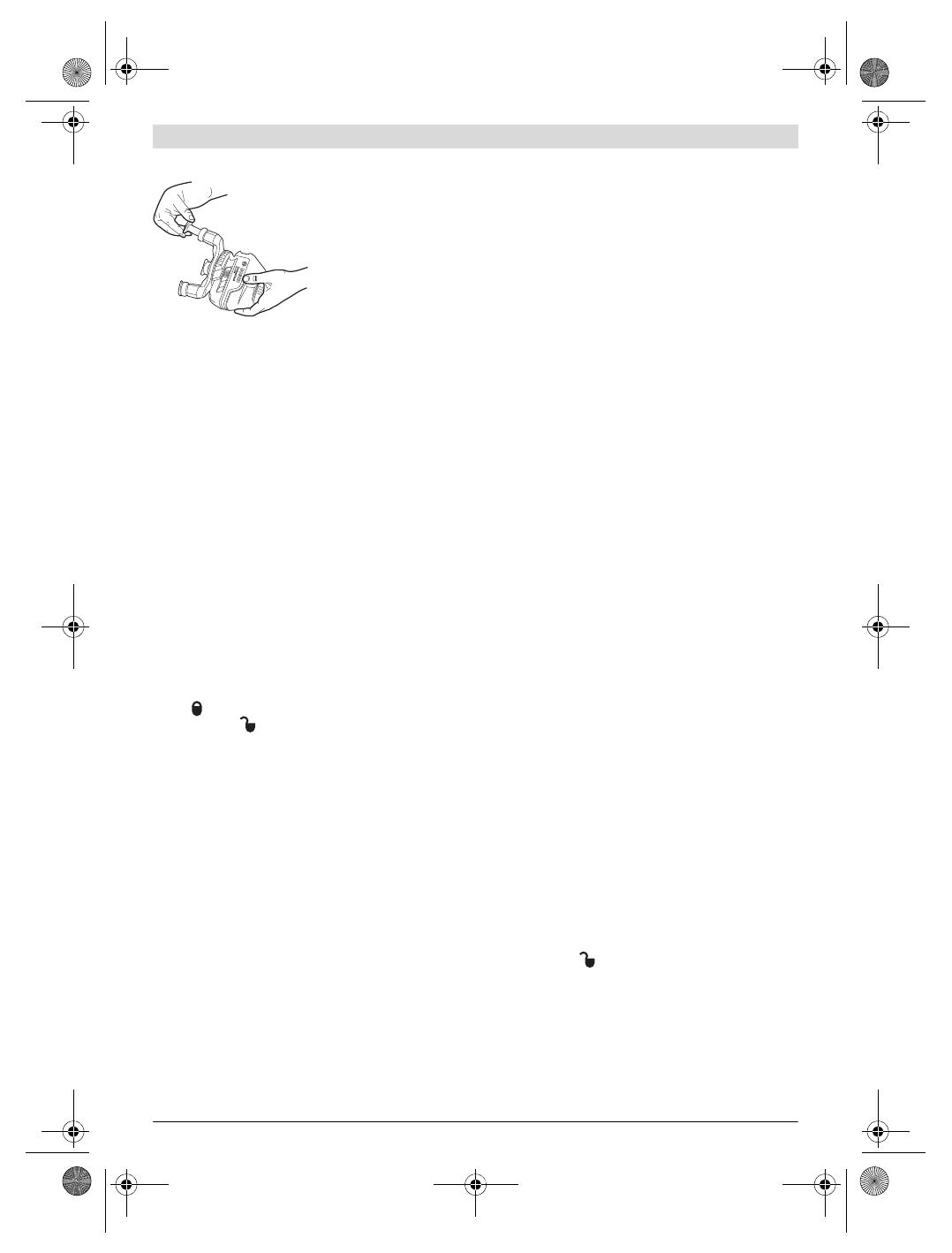
Extending the Telescopic Legs
Unscrew the locking screw
17 for the extendable
stand. Pull out the stand.
Lock the stand by tightening
the locking screw 17.
Repeat the process for the
other two stands.
Operation
Initial Operation
Protect the measuring tool against moisture and direct
sun light.
Do not subject the measuring tool to extreme tempera-
tures or variations in temperature. As an example, do
not leave it in vehicles for long time. In case of large varia-
tions in temperature, allow the measuring tool to adjust to
the ambient temperature before putting it into operation.
In case of extreme temperatures or variations in tempera-
ture, the accuracy of the measuring tool can be impaired.
Avoid heavy impact or falling of the measuring tool. Af-
ter heavy exterior impact on the measuring tool, an accura-
cy check should always be carried out before continuing to
work (see “Levelling Accuracy”).
Switch the measuring tool off during transport. When
switching off, the levelling unit, which can be damaged in
case of intense movement, is locked.
Switching On and Off
To switch on the measuring tool, slide the On/Off switch 14
to the “on position (when working without automatic lev-
elling) or to the “on position (when working with auto-
matic levelling). Immediately after switching on, the measur-
ing tool sends laser beams out of the exit openings 1.
Do not point the laser beam at persons or animals and
do not look into the laser beam yourself, not even from
a large distance.
To switch off the measuring tool, slide the On/Off switch 14
to the “off” position. When switching off, the levelling unit is
locked.
When exceeding the maximum permitted operating tempera-
ture of 40 °C, the measuring tool switches off to protect the
laser diode. After cooling down, the measuring tool is ready
for operation and can be switched on again.
Deactivating the Automatic Shut-off
The measuring tool switches off automatically after an operat-
ing duration of 30 minutes. To deactivate the automatic
switch-off, keep the operating mode button 4 pressed for 3 s
while switching on the measuring tool. When the automatic
switch-off is deactivated, the laser lines briefly flash after 3 s.
Do not leave the switched on measuring tool unattend-
ed and switch the measuring tool off after use. Other
persons could be blinded by the laser beam.
To activate the automatic shut-off, switch the measuring tool
off and then on again (without the operating mode button 4
pushed).
Operation Modes (see figures AD)
The measuring tool has four operating modes, between which
you can switch at any time:
Horizontal operation (operating mode A): generates a
horizontal laser line
Cross-line operation (operating mode B): generates a
horizontal and a vertical laser line
Vertical operation (operating mode C): generates two
vertical, orthogonal laser lines,
Horizontal operation combined with vertical operation
(operating mode D): generates a horizontal and two verti-
cal laser lines
In all operating modes, a perpendicular point is projected on-
to the floor.
Once switched on, the measuring tool is in operating mode
“D”. To change the operating mode, press the operating
mode button 4.
All four operating modes can be selected with or without auto-
matic levelling.
In cross-line and vertical operation, the vertical lines can be
aligned exactly on a measurement object using the handwheel
18.
Pulse Function
When working with the laser receiver 27, the pulse function
must be activated, – independent of the selected operating
mode.
In pulse function, the laser lines flash at very high frequency
and thus become detectable by the laser receiver 27.
To switch on the pulse function, press button 3. When the
pulse function is switched on, the pulse-function indicator 2
lights up green.
When the pulse function is switched on, the visibility of the la-
ser lines is reduced for the human eye. Therefore, shut off the
pulse function by pushing button 3 again when working with-
out laser receiver. When the pulse function is switched off,
the pulse-function indicator 2 is deactivated.
Automatic Levelling
Working with Automatic Levelling
Position the measuring tool on a level and firm support or at-
tach it to a commercially available photographic tripod.
When working with automatic levelling, push the On/Off
switch 14 to the “ on position.
After switching on, the levelling function automatically com-
pensates irregularities within the self-levelling range of ±4°.
The measuring tool is levelled in as soon as the laser lines no
longer flash.
If the automatic levelling function is not possible, e.g. be-
cause the surface on which the measuring tool stands devi-
ates by more than 4° from the horizontal plane, the laser
OBJ_BUCH-1973-002.book Page 14 Thursday, October 10, 2013 4:45 PM
English | 15
Bosch Power Tools 1 618 C00 99J | (10.10.13)
beams flash. In this case, bring the measuring tool to the level
position and wait for the self-levelling to take place.
In case of ground vibrations or position changes during opera-
tion, the measuring tool is automatically levelled in again. To
avoid errors, check the position of the horizontal and vertical la-
ser line with regard to the reference points upon re-levelling.
Working without Automatic Levelling
For work without automatic levelling, push the On/Off switch
14 to the “ on position. When the automatic levelling is
switched off, the laser lines flash continuously.
When the automatic levelling is switched off, the measuring
tool can be held by hand or placed on an inclined surface. In
cross-line operation, the two laser lines do not necessarily run
at a right angle to each other.
Levelling Accuracy
Influences on Accuracy
The ambient temperature has the greatest influence. Espe-
cially temperature differences occurring from the ground up-
ward can divert the laser beam.
Because the largest difference in temperature layers is close
to the ground, the measuring tool should always be mounted
on a tripod when measuring distances exceeding 20 m. If pos-
sible, also set up the measuring tool in the centre of the work
area.
Apart from exterior influences, device-specific influences
(such as heavy impact or falling down) can lead to deviations.
Therefore, check the accuracy of the measuring tool each
time before starting your work.
First, check both the height as well as the levelling accuracy of
the horizontal laser line, then the levelling accuracy of the ver-
tical laser line.
Should the measuring tool exceed the maximum deviation
during one of the tests, please have it repaired by a Bosch af-
ter-sales service.
Checking the Height Accuracy of the Horizontal Line
For this check, a free measuring distance of 5 m on a firm sur-
face between two walls A and B is required.
Mount the measuring tool onto a tripod or place it on a firm
and level surface close to wall A. Switch on the measuring
tool. Select cross-line operation with automatic levelling.
Direct the laser against the close wall A and allow the meas-
uring tool to level in. Mark the centre of the point where the
laser lines cross each other on the wall (point I).
Turn the measuring tool by 180°, allow it to level in and
mark the cross point of the laser lines on the opposite wall
B (point II).
Without turning the measuring tool, position it close to wall
B. Switch the measuring tool on and allow it to level in.
Align the height of the measuring tool (using a tripod or by
underlaying, if required) in such a manner that the cross
point of the laser lines is projected against the previously
marked point II on the wall B.
Without changing the height, turn around the measuring
tool by 180°. Direct it against the wall A in such a manner
that the vertical laser line runs through the already marked
point I. Allow the measuring tool to level in and mark the
cross point of the laser lines on the wall A (point III).
–The difference d of both marked points I and III on wall A
indicates the actual height deviation of the measuring tool.
The maximum permitted deviation d
max
is calculated as follows:
d
max
= double distance of the walls x 0.3 mm/m
Example: With a 5 metre distance between the walls, the max-
imum deviation must not exceed
d
max
= 2 x 5 m x 0.3 mm/m = 3 mm. Thus, the marks must not
be more than 3 mm apart.
A
B
5 m
A
B
180˚
A
B
d
180˚
A
B
OBJ_BUCH-1973-002.book Page 15 Thursday, October 10, 2013 4:45 PM
16 | English
1 618 C00 99J | (10.10.13) Bosch Power Tools
Checking the Levelling Accuracy of the Horizontal Line
For the check, a free surface of approx. 5 x 5 metres is re-
quired.
Set up the measuring tool on a firm, level surface between
both walls A and B. Allow the measuring tool to level in
while in horizontal operation.
At a distance of 2.5 metres from the measuring tool, mark
the centre of the laser line (point I on wall A and point II on
wall B) on both walls.
Set up the measuring tool 5 metres away turned by 180°
and allow it to level in.
Align the height of the measuring tool (using a tripod or by
underlaying, if required) in such a manner that the centre
of the laser line is projected exactly against the previously
marked point II on wall B.
Mark the centre of the laser line as point III (vertically
above or below point I) on the wall A.
–The difference d of both marked points I and III on wall A
indicates the actual deviation of the measuring tool from
the level plane.
The maximum permitted deviation d
max
is calculated as follows:
d
max
= double distance of the walls x 0.3 mm/m
Example: With a 5 metre distance between the walls, the max-
imum deviation must not exceed
d
max
=2x5mx0.3mm/m=3mm. Thus, the marks must not
be more than 3 mm apart.
Checking the Levelling Accuracy of the Vertical Line
For this check, a door opening is required with at least 2.5 m
of space (on a firm surface) to each side of the door.
Position the measuring tool on a firm, level surface (not on
a tripod) 2.5 m away from the door opening. Allow the
measuring tool to level in while in cross-line operation
mode, and direct the laser beams at the door opening.
Mark the centre of the vertical laser line at the floor of the
door opening (point I), at a distance of 5 m beyond the
other side of the door opening (point II) and at the upper
edge of the door opening (point III).
Position the measuring tool on the other side of the door
opening directly behind point II. Allow the measuring tool
to level in and align the vertical laser line in such a manner
that its centre runs exactly through points I and II.
–The difference d between point III and the centre of the la-
ser line at the upper edge of the door opening results in the
actual deviation of the measuring tool from the vertical
plane.
Measure the height of the door opening.
The maximum permitted deviation d
max
is calculated as follows:
d
max
= double height of the door opening
x0.3mm/m
Example: With a door opening height of 2 metres, the maxi-
mum permitted deviation is
d
max
= 2 x 2 m x 0.3 mm/m = 1.2 mm. Thus, the marks must
not be more than 1.2 mm apart.
2,5 m
,0 m
5
A
B
d
2,5 m
A
B
2,5 m
2,5 m
2 m
d
OBJ_BUCH-1973-002.book Page 16 Thursday, October 10, 2013 4:45 PM
English | 17
Bosch Power Tools 1 618 C00 99J | (10.10.13)
Checking plumb accuracy
For this check, a free measuring distance of approx. 5 m be-
tween floor and ceiling on a firm surface is required.
Mount the measuring tool onto the rotating platform and
place it on the floor.
Switch the measuring tool on and allow it to level.
Mark the centre of the upper crossing point on the ceiling
(point I). Also mark the centre of the bottom laser point on
the floor (point II).
Rotate the measuring tool 180°. Position it so that the cen-
tre of the lower laser point is on the point II which has al-
ready been marked. Allow the measuring tool to level.
Mark the centre of the upper laser point (point III).
The difference d of both marked points I and III on the ceil-
ing results in the actual deviation of the measuring tool to
the plumb line.
In the measuring distance of 5 m the maximum permissible
deviation is: 5 m x ±0.6 mm/m x 2 = ±6 mm.
The difference d between the points I and III can therefore be
at most 6 mm.
Working Advice
Always use the centre of the laser line for marking. The
width of the laser line changes with the distance.
Working with the Measuring Plate (Accessory)
(see figures GH)
With the measuring plate 26, it is possible to project the laser
mark onto the floor or the laser height onto a wall.
With the zero field and the scale, the offset or drop to the re-
quired height can be measured and projected at another loca-
tion. This eliminates the necessity of precisely adjusting the
measuring tool to the height to be projected.
The measuring plate 26 has a reflective coating that enhances
the visibility of the laser beam at greater distances or in in-
tense sunlight. The brightness intensification can be seen on-
ly when viewing, parallel to the laser beam, onto the measur-
ing plate.
Working with the Tripod (Accessory)
A tripod offers a stable, height-adjustable measuring support.
Position the measuring tool with the 5/8" tripod mount 11 on-
to the thread of the tripod 22 or a commercially available con-
struction tripod. For fastening to a commercially available
camera tripod, use the 1/4" tripod mount 6. Tighten the
measuring tool with the tripod mounting stud.
Working with the Laser Receiver (Accessory)
(see figure E)
Under unfavourable light conditions (bright environment, di-
rect sunlight) and for larger distances, use the laser receiver
for improved finding of the laser lines 27. When working with
the laser receiver, switch the pulse function on (see “Pulse
Function”, page 14).
Laser Viewing Glasses (Accessory)
The laser viewing glasses filter out the ambient light. This
makes the red light of the laser appear brighter for the eyes.
Do not use the laser viewing glasses as safety goggles.
The laser viewing glasses are used for improved visualisa-
tion of the laser beam, but they do not protect against laser
radiation.
Do not use the laser viewing glasses as sun glasses or in
traffic. The laser viewing glasses do not afford complete
UV protection and reduce colour perception.
Work Examples
Work Examples (see figures A F)
Applicational examples for the measuring tool can be found
on the graphics pages.
Maintenance and Service
Maintenance and Cleaning
Store and transport the measuring tool only in the supplied
case.
Keep the measuring tool clean at all times.
Do not immerse the measuring tool in water or other fluids.
Wipe off debris using a moist and soft cloth. Do not use any
cleaning agents or solvents.
Regularly clean the surfaces at the exit opening of the laser in
particular, and pay attention to any fluff of fibres.
For repairs, only send in the measuring tool in the case.
After-sales Service and Application Service
Our after-sales service responds to your questions concern-
ing maintenance and repair of your product as well as spare
parts. Exploded views and information on spare parts can al-
so be found under:
www.bosch-pt.com
Bosch’s application service team will gladly answer questions
concerning our products and their accessories.
5 m
180°
d
OBJ_BUCH-1973-002.book Page 17 Thursday, October 10, 2013 4:45 PM
18 | English
1 618 C00 99J | (10.10.13) Bosch Power Tools
In all correspondence and spare parts orders, please always
include the 10-digit article number given on the type plate of
the measuring tool.
Great Britain
Robert Bosch Ltd. (B.S.C.)
P.O. Box 98
Broadwater Park
North Orbital Road
Denham
Uxbridge
UB 9 5HJ
Tel. Service: (0844) 7360109
Fax: (0844) 7360146
Ireland
Origo Ltd.
Unit 23 Magna Drive
Magna Business Park
City West
Dublin 24
Tel. Service: (01) 4666700
Fax: (01) 4666888
Australia, New Zealand and Pacific Islands
Robert Bosch Australia Pty. Ltd.
Power Tools
Locked Bag 66
Clayton South VIC 3169
Customer Contact Center
Inside Australia:
Phone: (01300) 307044
Fax: (01300) 307045
Inside New Zealand:
Phone: (0800) 543353
Fax: (0800) 428570
Outside AU and NZ:
Phone: +61 3 95415555
www.bosch.com.au
Republic of South Africa
Customer service
Hotline: (011) 6519600
Gauteng – BSC Service Centre
35 Roper Street, New Centre
Johannesburg
Tel.: (011) 4939375
Fax: (011) 4930126
KZN – BSC Service Centre
Unit E, Almar Centre
143 Crompton Street
Pinetown
Tel.: (031) 7012120
Fax: (031) 7012446
Western Cape – BSC Service Centre
Democracy Way, Prosperity Park
Milnerton
Tel.: (021) 5512577
Fax: (021) 5513223
Bosch Headquarters
Midrand, Gauteng
Tel.: (011) 6519600
Fax: (011) 6519880
People’s Republic of China
China Mainland
Bosch Power Tools (China) Co., Ltd.
567, Bin Kang Road
Bin Jiang District 310052
Hangzhou, P.R.China
Service Hotline: 4008268484
Fax: (0571) 87774502
www.bosch-pt.com.cn
HK and Macau Special Administrative Regions
Robert Bosch Hong Kong Co. Ltd.
21st Floor, 625 King’s Road
North Point, Hong Kong
Customer Service Hotline: +852 2101 0235
Fax: +852 2590 9762
www.bosch-pt.com.hk
Indonesia
PT. Multi Mayaka
Kawasan Industri Pulogadung
Jalan Rawa Gelam III No. 2
Jakarta 13930
Indonesia
Tel.: (021) 46832522
Fax: (021) 46828645/6823
www.bosch-pt.co.id
Philippines
Robert Bosch, Inc.
28th Floor Fort Legend Towers,
3rd Avenue corner 31st Street,
Fort Bonifacio Global City,
1634 Taguig City, Philippines
Tel.: (02) 8703871
Fax: (02) 8703870
www.bosch-pt.com.ph
Bosch Service Center:
9725-27 Kamagong Street
San Antonio Village
Makati City, Philippines
Tel.: (02) 8999091
Fax: (02) 8976432
OBJ_BUCH-1973-002.book Page 18 Thursday, October 10, 2013 4:45 PM
Français | 19
Bosch Power Tools 1 618 C00 99J | (10.10.13)
Malaysia
Robert Bosch (S.E.A.) Sdn. Bhd.
No. 8A, Jalan 13/6
G.P.O. Box 10818
46200 Petaling Jaya
Selangor, Malaysia
Tel.: (03) 79663194
Fax: (03) 79583838
Toll-Free: 1800 880188
www.bosch-pt.com.my
Thailand
Robert Bosch Ltd.
Liberty Square Building
No. 287, 11 Floor
Silom Road, Bangrak
Bangkok 10500
Tel.: 02 6393111, 02 6393118
Fax: 02 2384783
Robert Bosch Ltd., P. O. Box 2054
Bangkok 10501, Thailand
www.bosch.co.th
Bosch Service – Training Centre
La Salle Tower Ground Floor Unit No.2
10/11 La Salle Moo 16
Srinakharin Road
Bangkaew, Bang Plee
Samutprakarn 10540
Thailand
Tel.: 02 7587555
Fax: 02 7587525
Singapore
Robert Bosch (SEA) Pte. Ltd.
11 Bishan Street 21
Singapore 573943
Tel.: 6571 2772
Fax: 6350 5315
Toll-Free: 1800 3338333
www.bosch-pt.com.sg
Vietnam
Robert Bosch Vietnam Co. Ltd
10/F, 194 Golden Building
473 Dien Bien Phu Street
Ward 25, Binh Thanh District
84 Ho Chi Minh City
Vietnam
Tel.: (08) 6258 3690 ext. 413
Fax: (08) 6258 3692
www.bosch-pt.com
Disposal
Measuring tools, accessories and packaging should be sorted
for environmental-friendly recycling.
Do not dispose of measuring tools and batteries/rechargea-
ble batteries into household waste!
Only for EC countries:
According to the European Guideline
2012/19/EU, measuring tools that are no
longer usable, and according to the Europe-
an Guideline 2006/66/EC, defective or
used battery packs/batteries, must be col-
lected separately and disposed of in an
environmentally correct manner.
Battery packs/batteries:
Do not dispose of battery packs/batteries into household
waste, fire or water. Battery packs/batteries should, if possi-
ble, be discharged, collected, recycled or disposed of in an
environmental-friendly manner.
Batteries no longer suitable for use can be directly returned at:
Great Britain
Robert Bosch Ltd. (B.S.C.)
P.O. Box 98
Broadwater Park
North Orbital Road
Denham
Uxbridge
UB 9 5HJ
Tel. Service: (0844) 7360109
Fax: (0844) 7360146
Subject to change without notice.
Français
Avertissements de sécurité
Il est impératif que toutes les instructions
soient lues et prises en compte pour pou-
voir travailler sans risques et en toute sécu-
rité avec cet appareil de mesure. Veillez à ce
que les plaques signalétiques se trouvant
sur l’appareil de mesure restent toujours
lisibles. CONSERVEZ SOIGNEUSEMENT
CES INSTRUCTIONS DE SECURITE.
Attention – si d’autres dispositifs d’utilisation ou
d’ajustage que ceux indiqués ici sont utilisés ou si
d’autres procédés sont appliqués, ceci peut entraîner
une exposition dangereuse au rayonnement.
Cet appareil de mesure est fourni avec une plaque
d’avertissement en langue anglaise (dans la représen-
tation de l’appareil de mesure se trouvant sur la page
des graphiques elle est marquée du numéro 12).
OBJ_BUCH-1973-002.book Page 19 Thursday, October 10, 2013 4:45 PM
  • Page 1 1
  • Page 2 2
  • Page 3 3
  • Page 4 4
  • Page 5 5
  • Page 6 6
  • Page 7 7
  • Page 8 8
  • Page 9 9
  • Page 10 10
  • Page 11 11
  • Page 12 12
  • Page 13 13
  • Page 14 14
  • Page 15 15
  • Page 16 16
  • Page 17 17
  • Page 18 18
  • Page 19 19
  • Page 20 20
  • Page 21 21
  • Page 22 22
  • Page 23 23
  • Page 24 24
  • Page 25 25
  • Page 26 26
  • Page 27 27
  • Page 28 28
  • Page 29 29
  • Page 30 30
  • Page 31 31
  • Page 32 32
  • Page 33 33
  • Page 34 34
  • Page 35 35
  • Page 36 36
  • Page 37 37
  • Page 38 38
  • Page 39 39
  • Page 40 40
  • Page 41 41
  • Page 42 42
  • Page 43 43
  • Page 44 44
  • Page 45 45
  • Page 46 46
  • Page 47 47
  • Page 48 48
  • Page 49 49
  • Page 50 50
  • Page 51 51
  • Page 52 52
  • Page 53 53
  • Page 54 54
  • Page 55 55
  • Page 56 56
  • Page 57 57
  • Page 58 58
  • Page 59 59
  • Page 60 60
  • Page 61 61
  • Page 62 62
  • Page 63 63
  • Page 64 64
  • Page 65 65
  • Page 66 66
  • Page 67 67
  • Page 68 68
  • Page 69 69
  • Page 70 70
  • Page 71 71
  • Page 72 72
  • Page 73 73
  • Page 74 74
  • Page 75 75
  • Page 76 76
  • Page 77 77
  • Page 78 78
  • Page 79 79
  • Page 80 80
  • Page 81 81
  • Page 82 82
  • Page 83 83
  • Page 84 84
  • Page 85 85
  • Page 86 86
  • Page 87 87
  • Page 88 88
  • Page 89 89
  • Page 90 90
  • Page 91 91
  • Page 92 92
  • Page 93 93
  • Page 94 94
  • Page 95 95
  • Page 96 96
  • Page 97 97
  • Page 98 98
  • Page 99 99
  • Page 100 100
  • Page 101 101
  • Page 102 102
  • Page 103 103
  • Page 104 104
  • Page 105 105
  • Page 106 106
  • Page 107 107
  • Page 108 108
  • Page 109 109
  • Page 110 110
  • Page 111 111
  • Page 112 112
  • Page 113 113
  • Page 114 114
  • Page 115 115
  • Page 116 116
  • Page 117 117
  • Page 118 118
  • Page 119 119
  • Page 120 120
  • Page 121 121
  • Page 122 122
  • Page 123 123
  • Page 124 124
  • Page 125 125
  • Page 126 126
  • Page 127 127
  • Page 128 128
  • Page 129 129
  • Page 130 130
  • Page 131 131
  • Page 132 132
  • Page 133 133
  • Page 134 134
  • Page 135 135
  • Page 136 136
  • Page 137 137
  • Page 138 138
  • Page 139 139
  • Page 140 140
  • Page 141 141
  • Page 142 142
  • Page 143 143
  • Page 144 144
  • Page 145 145
  • Page 146 146
  • Page 147 147
  • Page 148 148
  • Page 149 149
  • Page 150 150
  • Page 151 151
  • Page 152 152
  • Page 153 153
  • Page 154 154
  • Page 155 155
  • Page 156 156
  • Page 157 157
  • Page 158 158
  • Page 159 159
  • Page 160 160
  • Page 161 161
  • Page 162 162
  • Page 163 163
  • Page 164 164
  • Page 165 165
  • Page 166 166
  • Page 167 167
  • Page 168 168
  • Page 169 169
  • Page 170 170
  • Page 171 171
  • Page 172 172
  • Page 173 173
  • Page 174 174
  • Page 175 175
  • Page 176 176
  • Page 177 177
  • Page 178 178
  • Page 179 179
  • Page 180 180
  • Page 181 181
  • Page 182 182
  • Page 183 183
  • Page 184 184
  • Page 185 185
  • Page 186 186
  • Page 187 187
  • Page 188 188
  • Page 189 189
  • Page 190 190
  • Page 191 191
  • Page 192 192
  • Page 193 193
  • Page 194 194
  • Page 195 195
  • Page 196 196
  • Page 197 197
  • Page 198 198
  • Page 199 199
  • Page 200 200
  • Page 201 201
  • Page 202 202
  • Page 203 203
  • Page 204 204
  • Page 205 205
  • Page 206 206
  • Page 207 207
  • Page 208 208
  • Page 209 209
  • Page 210 210
  • Page 211 211
  • Page 212 212
  • Page 213 213
  • Page 214 214
  • Page 215 215
  • Page 216 216
  • Page 217 217
  • Page 218 218
  • Page 219 219
  • Page 220 220
  • Page 221 221
  • Page 222 222
  • Page 223 223
  • Page 224 224
  • Page 225 225
  • Page 226 226
  • Page 227 227
  • Page 228 228
  • Page 229 229
  • Page 230 230
  • Page 231 231
  • Page 232 232
  • Page 233 233
  • Page 234 234
  • Page 235 235
  • Page 236 236
  • Page 237 237
  • Page 238 238
  • Page 239 239

Bosch GLL 3-50 Owner's manual

Category
Rangefinders
Type
Owner's manual
This manual is also suitable for

Ask a question and I''ll find the answer in the document

Finding information in a document is now easier with AI