
DEWALT Industrial Tool Co., 701 East Joppa Road, Baltimore, MD 21286 (JUL03-1) Form No. 581054-00
D25101, D25103, D25201, D25203, D25303, D25304
Copyright © 2003
The following are trademarks for one or more D
EWALT power tools: the yellow and black color scheme; the “D” shaped air intake grill; the array of
pyramids on the handgrip; the kit box configuration; and the array of lozenge-shaped humps on the surface of the tool.

INSTRUCTION MANUAL
GUIDE D'UTILISATION
MANUAL DE INSTRUCCIONES
D25101, D25103, D25201, D25203, D25303, D25304
1" Heavy Duty SDS Rotary Hammers
Perceuses rotatives SDS 26 mm (1 po) de service intensif
Rotomartillos SDS 26 mm (1") para trabajo pesado
INSTRUCTIVO DE OPERACIÓN, CENTROS DE SERVICIO Y PÓLIZA
DE GARANTÍA. ADVERTENCIA: LÉASE ESTE INSTRUCTIVO ANTES
DE USAR EL PRODUCTO.
Questions? See us in the World Wide Web at www.dewalt.com
Page is loading ...

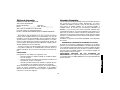
General Safety Rules
WARNING! READ AND UNDERSTAND ALL INSTRUCTIONS.
Failure to follow all instructions listed below may result in electric
shock, fire and/or serious personal injury.
SAVE THESE INSTRUCTIONS
WORK AREA
• Keep your work area clean and well lit. Cluttered benches and
dark areas invite accidents.
• Do not operate power tools in explosive atmospheres, such
as in the presence of flammable liquids, gases, or dust. Power
tools create sparks which may ignite the dust or fumes.
• Keep bystanders, children, and visitors away while operating
a power tool. Distractions can cause you to lose control.
ELECTRICAL SAFETY
• Grounded tools must be plugged into an outlet properly
installed and grounded in accordance with all codes and ordi-
nances. Never remove the grounding prong or modify the
plug in any way. Do not use any adapter plugs. Check with a
qualified electrician if you are in doubt as to whether the out-
let is properly grounded. If the tools should electrically malfunc-
tion or break down, grounding provides a low resistance path to
carry electricity away from the user. Applicable only to Class I
(grounded) tools.
• Double insulated tools are equipped with a polarized plug
(one blade is wider than the other.) This plug will fit in a polar-
ized outlet only one way. If the plug does not fit fully in the out-
let, reverse the plug. If it still does not fit, contact a qualified
electrician to install a polarized outlet. Do not change the plug
1
English
in any way. Double insulation eliminates the need for the three
wire grounded power cord and grounded power supply system.
Applicable only to Class II (double insulated) tools.
• Avoid body contact with grounded surfaces such as pipes,
radiators, ranges and refrigerators. There is an increased risk of
electric shock if your body is grounded.
• Don’t expose power tools to rain or wet conditions. Water
entering a power tool will increase the risk of electric shock. Other
liquids, such as perspiration present the same hazard.
• Do not abuse the cord. Never use the cord to carry the tools
or pull the plug from an outlet. Keep cord away from heat, oil,
sharp edges or moving parts. Replace damaged cords imme-
diately. Damaged cords increase the risk of electric shock.
• When operating a power tool outside, use an outdoor exten-
sion cord marked “W-A” or “W.” These cords are rated for out-
door use and reduce the risk of electric shock. When using an
extension cord, be sure to use one heavy enough to carry the cur-
rent your product will draw. An undersized cord will cause a drop in
line voltage resulting in loss of power and overheating. The follow-
ing table shows the correct size to use depending on cord length
and nameplate ampere rating. If in doubt, use the next heavier
gage. The smaller the gage number, the heavier the cord.
Minimum Gage for Cord Sets
Volts Total Length of Cord in Feet
120V 0-25 26-50 51-100 101-150
Ampere Rating
More Not more AWG
Than Than
6-10 18 16 14 12
IF YOU HAVE ANY QUESTIONS OR COMMENTS ABOUT THIS OR
ANY D
EWALT TOOL, CALL US TOLL FREE AT:
1-800-4-DEWALT (1-800-433-9258)

• Disconnect the plug from the power source before making
any adjustments, changing accessories, or storing the tool.
Such preventative safety measures reduce the risk of starting the
tool accidentally.
• Store idle tools out of reach of children and other untrained
persons. Tools are dangerous in the hands of untrained users.
• Maintain tools with care. Keep cutting tools sharp and clean.
Properly maintained tools, with sharp cutting edges are less likely
to bind and are easier to control.
• Check for misalignment or binding of moving parts, breakage
of parts, and any other condition that may affect the tools
operation. If damaged, have the tool serviced before using.
Many accidents are caused by poorly maintained tools.
• Use only accessories that are recommended by the manufac-
turer for your model. Accessories that may be suitable for one
tool, may become hazardous when used on another tool.
SERVICE
• Tool service must be performed only by qualified repair per-
sonnel. Service or maintenance performed by unqualified person-
nel could result in a risk of injury.
• When servicing a tool, use only identical replacement parts.
Follow instructions in the Maintenance section of this manu-
al. Use of unauthorized parts or failure to follow Maintenance
Instructions may create a risk of electric shock or injury.
Additional Specific Safety Rules for
Rotary Hammers
• Hold tool by insulated gripping surfaces when performing an
operation where the cutting tool may contact hidden wiring or
its own cord. Contact with a “live” wire will make exposed metal
parts of the tool “live” and shock the operator.
• Wear ear protectors when hammering for extended periods of
time. Prolonged exposure to high intensity noise can cause hear-
ing loss.
2
PERSONAL SAFETY
• Stay alert, watch what you are doing and use common sense
when operating a power tool. Do not use tool while tired or
under the influence of drugs, alcohol, or medication. A
moment of inattention while operating power tools may result in
serious personal injury,
• Dress properly. Do not wear loose clothing or jewelry. Contain
long hair. Keep your hair, clothing, and gloves away from
moving parts. Loose clothing, jewelry, or long hair can be caught
in moving parts. Air vents often cover moving parts and should also
be avoided.
• Avoid accidental starting. Be sure switch is off before plug-
ging in. Carrying tools with your finger on the switch or plugging in
tools that have the switch on invites accidents.
• Remove adjusting keys or wrenches before turning the tool
on. A wrench or key that is left attached to a rotating part of the tool
may result in personal injury.
• Do not overreach. Keep proper footing and balance at all
times. Proper footing and balance enables better control of the tool
in unexpected situations.
• Use safety equipment. Always wear eye protection. Dust mask,
non-skid safety shoes, hard hat, or hearing protection must be
used for appropriate conditions.
TOOL USE AND CARE
• Use clamps or other practical way to secure and support the
workpiece to a stable platform. Holding the work by hand or
against your body is unstable and may lead to a loss of control.
• Do not force tool. Use the correct tool for your application. The
correct tool will do the job better and safer and the rate for which it
is designed.
• Do not use tool if switch does not turn it on or off. Any tool that
cannot be controlled with the switch is dangerous and must be
repaired.
English

• Avoid prolonged contact with dust from power sanding, saw-
ing, grinding, drilling, and other construction activities. Wear
protective clothing and wash exposed areas with soap and
water. Allowing dust to get into your mouth, eyes, or lay on the skin
may promote absorption of harmful chemicals.
• The label on your tool may include the following symbols. The sym-
bols and their definitions are as follows:
V..........volts A ..........amperes
Hz........hertz W ..........watts
min ......minutes ........alternating current
....direct current
n
o ........no load speed
........Class II Construction ..........earthing terminal
........safety alert symbol .../min....revolutions
BPM ....beats per minute ..............per minute
WARNING: Use of this product will expose you to chemicals
known to the State of California to cause cancer, birth defects and
other reproductive harm. Avoid inhaling vapors and dust, and
wash hands after using.
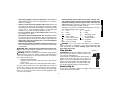
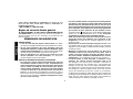
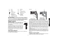
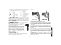
Side Handle
CAUTION: Hold the side handle and body of the
tool firmly with both hands to maintain control of the
tool at start up and during use.
A side handle is supplied with this rotary hammer. It
clamps to the front of the gear case as shown in
Figure 1 and can be rotated 360˚ to permit right or left
hand use. The side handle can be tightened by rotat-
ing the black plastic portion of the side handle clock-
wise and loosened by rotating it counterclockwise.
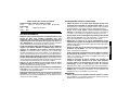
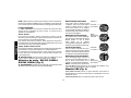
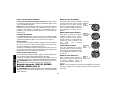
Switch (Fig. 2)
To start the rotary hammer, depress the trigger switch (A). To stop
rotary hammer, release the switch.
3
English
• Wear safety goggles or other eye protection. Hammering and
drilling operations cause chips to fly. Flying particles can cause per-
manent eye damage.
• Always use the side handle supplied with the tool. Keep a firm
grip on the tool at all times. Do not attempt to operate this tool with-
out holding it with both hands. Operating this tool with one hand will
result in loss of control. Breaking through or encountering hard
materials such as re-bar may be be hazardous as well.
• Do not use chisels in any of the rotation modes. Chisels may
jam causing loss of control.
• Wear gloves when handling hammer bits and tools. Hammer
bits and tools get hot during operation. Gloves and frequent rest
periods will reduce the risk of vibration damage to hands and arms.
• Keep gloves away from rotating bits to avoid entanglement
with bit and possible injury.
• Keep hands and body from between the tool and wall or post,
etc., to avoid being crushed by the tool should it twist unexpectedly
if the bit binds.
CAUTION: Wear appropriate personal hearing protection dur-
ing use. Under some conditions and duration of use, noise from this
product may contribute to hearing loss.
WARNING: Some dust created by power sanding, sawing, grinding,
drilling, and other construction activities contains chemicals known to
cause cancer, birth defects or other reproductive harm. Some exam-
ples of these chemicals are:
• lead from lead-based paints,
• crystalline silica from bricks and cement and other masonry
products, and
• arsenic and chromium from chemically-treated lumber (CCA).
Your risk from these exposures varies, depending on how often you
do this type of work. To reduce your exposure to these chemicals:
work in a well ventilated area, and work with approved safety equip-
ment, such as those dust masks that are specially designed to filter
out microscopic particles.
FIGURE 1

4
VARIABLE SPEED TRIGGER
The variable speed trigger switch (A) permits speed control. The
farther the trigger switch is depressed, the higher the speed of the drill.
NOTE: Use lower speeds for starting holes without a centerpunch,
drilling in metal, plastics or ceramics, or driving screws. Higher speeds
are better for drilling in masonry for maximum efficiency.
REVERSING LEVER
The reversing lever is used to reverse the rotary hammer for backing
out screws or jammed bits. It is located above the trigger, shown in
Figure 2.
D25101, D25103
To reverse the rotary hammer, turn it OFF and align the reversing lever
(C) with the yellow arrow pointing backward (viewed when holding drill
in operating position).
To position the lever for forward operation, turn the rotary hammer OFF
and align the reversing lever with the yellow arrow pointing forward
(viewed when holding drill in operating position).
D25201, D25203, D25303, D25304
To reverse the rotary hammer, turn it OFF and push the reversing lever
in so the yellow arrow pointing backwards shows.
To position the lever for forward operation, turn the rotary hammer
OFF and push the reversing lever in so the yellow arrow pointing
forward shows.
CAUTION: When reversing to clear jammed bits, be ready for
strong reactive torque.
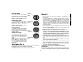
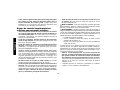
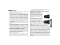
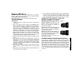
Mode Selector – D25103, D25203,
D25303, D25304 (Fig. 3)
CAUTION: Tool must come to a complete stop before activating
the mode actuator button or damage to the tool may result.
English
LOCK ON BUTTON (D25101, D25103 ONLY)
To lock the trigger switch in the ON position for continuous operation,
depress the trigger switch and slide up the lock on button (B). The
tool will continue to run.
To turn the tool OFF from a locked ON condition, squeeze once then
release the trigger. Before using the tool each time, be sure that the
lock on button release mechanism is working freely.
Do not lock the switch ON when drilling by hand so that you can
instantly release the trigger switch if the bit binds in the hole. The lock
on button is for use only when the rotary hammer is mounted in a drill
press stand or otherwise held stationary.
CAUTION: Be sure to release the locking mechanism before
disconnecting the plug from the power supply. Failure to do so will
cause the rotary hammer to start immediately the next time it is
plugged in. Damage or injury could result.
FIGURE 2
B
C
A
D25101, D25103
D25201, D25203,
D25303, D25304
C
A

DRILL-ONLY MODE
To use drill-only mode, depress button
(D) and turn the dial so the yellow
arrow points to the corresponding
symbol as shown. Use drill-only mode
for wood, metal, and plastics.
HAMMER/DRILL MODE
To use hammer/drill mode, depress
the button and turn the dial so the
yellow arrow points to the corre-
sponding symbol as shown. Use this
mode for masonry drilling.
CHISEL ROTATION
To manually rotate the chisel, depress
the button and turn the dial so the yel-
low arrow points to the corresponding
symbol as shown.
HAMMER-ONLY MODE
For light chiseling, depress the button
and turn the dial so the yellow arrow
points to the corresponding symbol as
shown.
NOTE: The yellow arrow on the mode
selector MUST be aligned with the
one of the symbols at all times. There
are no operable positions between
the positions.
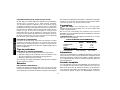
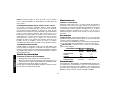
SDS Chuck (Fig. 4)
To insert bit, insert shank of bit about 3/4" into chuck. Push and rotate
bit until it locks in place. The bit will be securely held.
To release bit, pull the sleeve (D) back and remove the bit.
5
English
Operation
DRILLING
1. Always unplug the drill when attaching or changing bits or
accessories.
2. Use sharp drill bits only. For WOOD, use twist drill bits, spade bits,
power auger bits, or hole saws. For METAL, use steel twist drill
bits or hole saws. For MASONRY, such as brick, cement, cinder
block, etc., use carbide-tipped bits rated for percussion drilling. Be
sure the material to be drilled is anchored or clamped firmly. If
drilling thin material, use a wood “back-up” block to prevent dam-
age to the material.
3. Always apply pressure in a straight line with the bit. Use enough
pressure to keep drill biting, but do not push hard enough to stall
the motor or deflect the bit.
4. Hold tool firmly to control the twisting action of the drill.
5. IF DRILL STALLS, it is usually because it is being overloaded or
improperly used. RELEASE TRIGGER IMMEDIATELY, remove
drill bit from work, and determine cause of stalling. DO NOT
CLICK TRIGGER ON AND OFF IN AN ATTEMPT TO START A
STALLED DRILL — THIS CAN DAMAGE THE DRILL.
6. To minimize stalling or breaking through the material, reduce pres-
sure on drill and ease the bit through the last fractional part of the
hole.
7. Keep the motor running when pulling the bit back out of a drilled
hole. This will help prevent jamming.
8. With variable speed drills there is no need to center punch the
point to be drilled. Use a slow speed to start the hole and accel-
erate by squeezing the trigger harder when the hole is deep
enough to drill without the bit skipping out.
REMOVABLE SDS CHUCK & 3 JAW KEYLESS CHUCK
(D25304 ONLY)
The D25304 is equipped with a removable quick change SDS chuck
as well as a removable 3 jaw keyless chuck. The hammer mechanism
DRILL-ONLY
MODE
HAMMER/DRILL
MODE
CHISEL
ROTATION
HAMMER-ONLY
MODE
D
D
FIGURE 3

6
does not function when the 3 jaw keyless
chuck is used.
Both the SDS and 3 jaw keyless chuck can
be easily removed by turning the collar (E)
into the unlocked position (F) to release the
chuck (Fig. 4).
The SDS and 3 jaw keyless chuck can be
easily attached by inserting the chuck into
the spindle of the tool and turning the collar
to the locked position (G). The chuck will
click when properly installed.
DRILLING IN METAL
(D25103, D25203, D25303, D25304)
An SDS to round shank adaptor chuck is required. Ensure that tool is
in drill-only mode. (D25101, D25201 has no drill-only mode). Start
drilling with slow speed and increase to full power while applying firm
pressure on the tool. A smooth even flow of metal chips indicates the
proper drilling rate. Use a cutting lubricant when drilling metals. The
exceptions are cast iron and brass which should be drilled dry. The
cutting lubricants that work best are sulphurized cutting oil or lard oil;
bacon-grease will also serve the purpose.
NOTE: Large (5/16" to 1/2") holes in steel can be made easier if a pilot
hole (5/32" to 3/16") is drilled first.
DRILLING IN WOOD
(D25103, D25203, D25303, D25304)
An SDS to round shank adaptor chuck is required. Ensure that tool is
in drill-only mode. (D25101, D25201 have no drill-only mode). Start
drilling with slow speed and increase to full power while applying firm
pressure on the tool. Holes in wood can be made with the same twist
drills used for metal. These bits may overheat unless pulled out fre-
quently to clear chips from the flutes. For larger holes, use spade bits,
power auger bits, or hole saws. Work that is apt to splinter should be
backed up with a block of wood.
DRILLING IN MASONRY
When drilling in masonry, use SDS carbide tipped bits rated for per-
cussion drilling and be certain that the bit is sharp. Use a constant and
firm force on the tool to drill most effectively. A smooth, even flow of
dust indicates the proper drilling rate.
Depth Rod
TO ADJUST THE DEPTH ROD
1. Push in and hold the button on the side handle.
2. Move the rod so the distance between the end of the rod and the
end of the bit equals the desired drilling depth.
3. Release the button to lock rod into position.
When drilling with the depth rod, stop when end of rod reaches
surface of material.
Maintenance
CLEANING & LUBRICATION
Use only mild soap and damp cloth to clean the tool. Never let any liq-
uid get inside the tool; never immerse any part of the tool into a liquid.
Self-lubricating bearings are used in the tool and periodic relubrication
is not required. In the unlikely event that service is ever needed, take
your tool to an authorized service location.
Accessories
CAUTION: When handling accessories after use, wear work
gloves. Accessories may be hot and may burn skin.
Recommended accessories for use with your tool are available at
extra cost from your distributor or local service center.
CAUTION: The use of any non-recommended accessory may be
hazardous.
English
FIGURE 4
D
G
F
E

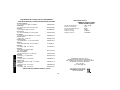
MAXIMUM RECOMMENDED CAPACITIES
D25101 D25103, D25203
D25201 D25303, D25304
MASONRY 1" 1"
STEEL N/A 1/2"
WOOD N/A 1 1/2"
OPTIMUM CAPACITY
MASONRY 5/32"-5/8" 5/32"-5/8"
Repairs
To assure product SAFETY and RELIABILITY, repairs, maintenance
and adjustment (including brush inspection and replacement) should
be performed by authorized service centers or other qualified service
organizations, always using identical replacement parts.
Full Warranty
DEWALT heavy duty industrial tools are warranted for one year from
date of purchase. We will repair, without charge, any defects due to
faulty materials or workmanship. For warranty repair information, call
1-800-4-D
EWALT. This warranty does not apply to accessories or
damage caused where repairs have been made or attempted by oth-
ers. This warranty gives you specific legal rights and you may have
other rights which vary in certain states or provinces.
In addition to the warranty, D
EWALT tools are covered by our:
30 DAY NO RISK SATISFACTION GUARANTEE
If you are not completely satisfied with the performance of your
D
EWALT heavy duty industrial tool, simply return it to the participating
seller within 30 days for a full refund. Please return the complete unit,
transportation prepaid. Proof of purchase may be required.
FREE WARNING LABEL REPLACEMENT: If your warning labels
become illegible or are missing, call 1-800-4-D
EWALT for a free
replacement.
7
English
Page is loading ...
Page is loading ...
Page is loading ...
Page is loading ...
Page is loading ...
Page is loading ...
Page is loading ...
Page is loading ...
Page is loading ...
Page is loading ...
Page is loading ...
Page is loading ...
Page is loading ...
Page is loading ...
Page is loading ...
Page is loading ...
Page is loading ...
-
 1
1
-
 2
2
-
 3
3
-
 4
4
-
 5
5
-
 6
6
-
 7
7
-
 8
8
-
 9
9
-
 10
10
-
 11
11
-
 12
12
-
 13
13
-
 14
14
-
 15
15
-
 16
16
-
 17
17
-
 18
18
-
 19
19
-
 20
20
-
 21
21
-
 22
22
-
 23
23
-
 24
24
-
 25
25
-
 26
26
-
 27
27


Ask a question and I''ll find the answer in the document
Finding information in a document is now easier with AI
in other languages
- français: DeWalt 581054-00 Manuel utilisateur
- español: DeWalt 581054-00 Manual de usuario
Related papers
Other documents
-
Black & Decker ET1245 User manual
-
Ryobi SDS65 User manual
-
Bosch RH432VCQ User manual
-
Bosch Power Tools 11224VSRC User manual
-
-
Bosch Power Tools 11255VSR User manual
-
Bosch 11255VSR User manual
-
-
-