Page is loading ...

VAA-2E1A-CB10-SJ/E2J-FL,
VAA-2E2A-CB10-SJ/E2J-FL
AS-Interface Safety at Work
Version 2.0
Manual

With regard to the supply of products, the current issue of the following document is applicable: The
General Terms of Delivery for Products and Services of the Electrical Industry, published by the Central
Association of the Electrical Industry (Zentralverband Elektrotechnik und Elektroindustrie (ZVEI) e.V.)
in its most recent version as well as the supplementary clause: "Expanded reservation of proprietor-
ship"
Worldwide
Pepperl+Fuchs Group
Lilienthalstr. 200
68307 Mannheim
Germany
Phone: +49 621 776 - 0
E-mail: [email protected]
North American Headquarters
Pepperl+Fuchs Inc.
1600 Enterprise Parkway
Twinsburg, Ohio 44087
USA
Phone: +1 330 425-3555
E-mail: sales@us.pepperl-fuchs.com
Asia Headquarters
Pepperl+Fuchs Pte. Ltd.
P+F Building
18 Ayer Rajah Crescent
Singapore 139942
Phone: +65 6779-9091
E-mail: sales@sg.pepperl-fuchs.com
https://www.pepperl-fuchs.com

3
VAA-2E1A-CB10-SJ/E2J-FL, VAA-2E2A-CB10-SJ/E2J-FL
Contents
2019-12
1 Declaration of Conformity......................................................................................... 5
2 Safety .......................................................................................................................... 6
2.1 Symbols Used ................................................................................................ 6
2.2 Intended Use .................................................................................................. 6
2.3 General Safety Information........................................................................... 7
2.4 Residual Risk ................................................................................................. 7
2.5 Safety Monitor Requirements....................................................................... 7
2.6 Cabling Requirements................................................................................... 8
2.7 Switch or Mechanical Contact Requirements............................................. 8
2.8 Fault Eliminations .......................................................................................... 8
2.9 Transmission Time for Safety-Related Information .................................... 8
2.10 Probability of Failure on Demand Calculation ............................................ 8
3 Product Description .................................................................................................. 9
3.1 Function.......................................................................................................... 9
3.2 Slave Profile ................................................................................................... 9
3.3 Indicators and Operating Elements ........................................................... 10
3.4 Connections ................................................................................................. 11
3.5 Operating Principle...................................................................................... 12
3.5.1 Safety-Related Inputs ...................................................................... 12
3.5.2 Cross Circuit Monitoring of Inputs .................................................... 13
3.6 Scope of Delivery......................................................................................... 13
4 Installation................................................................................................................ 14
4.1 Mounting....................................................................................................... 14
4.2 Connecting Inputs and Outputs ................................................................. 15
5 Commissioning........................................................................................................ 17
5.1 Configuring the AS-Interface Safety Monitor............................................ 17
5.2 Assigning an Address to the Module......................................................... 17
5.3 Operational Testing...................................................................................... 17
5.4 Operating Mode ........................................................................................... 17

VAA-2E1A-CB10-SJ/E2J-FL, VAA-2E2A-CB10-SJ/E2J-FL
Contents
4
2019-12
6 Operation ..................................................................................................................18
6.1 Safety-Related Inputs ..................................................................................18
6.2 Conventional (Non-Safe) Electronic Outputs............................................18
7 Servicing...................................................................................................................19
8 Troubleshooting .......................................................................................................20

VAA-2E1A-CB10-SJ/E2J-FL, VAA-2E2A-CB10-SJ/E2J-FL
Declaration of Conformity
2019-12
5
1 Declaration of Conformity
This product was developed and manufactured in line with the applicable European standards
and directives.
The product manufacturer, Pepperl+Fuchs GmbH, 68307 Mannheim, Germany, has a certified
quality assurance system that conforms to ISO 9001.
Note
A declaration of conformity can be requested from the manufacturer.
ISO9001

2019-12
6
VAA-2E1A-CB10-SJ/E2J-FL, VAA-2E2A-CB10-SJ/E2J-FL
Safety
2 Safety
2.1 Symbols Used
Safety-Relevant Symbols
Informative Symbols
Action
This symbol indicates a paragraph with instructions. You are prompted to perform an action or
a sequence of actions.
2.2 Intended Use
The device can be used as a safety module with safety-related inputs for connecting mechani-
cal contacts, such as emergency-stop switches, and an optional conventional electronic out-
put, e.g., to activate signal lights. When used in this way in conjunction with a programmed AS-
Interface safety monitor, the device allows operation of sensor-controlled personal protective
equipment up to category 4/PL e as per ISO 13849-1, or up to SIL 3 as per EN/IEC 62061.
The maximum service life of the AS-Interface safety module is 20 years. Replace the device as
a matter of course after 20 years at the latest.
Safety Classification
The module contains two independent, redundant input channels. If both input channels are
used, the module is suitable for use up to category 4/PL e in accordance with ISO 13849-1, or
SIL 3 in accordance with EN/IEC 61508 and EN/IEC 62061. In this case, the monitor must be
programmed so that dual-channel switching is monitored.
If a single-channel switch is used, the module is suitable for use up to category 2/PL c in accor-
dance with ISO 13849-1, or SIL 1 in accordance with EN/IEC 61508 and EN/IEC 62061. Only
tested and certified power supplies with safe isolation may be used to supply power. These
power supplies must have PELV voltage in accordance with EN 50295/IEC 62026-2, and a
minimum MTBF of 50 years. The power supplies are designed to exclude a short circuit
between the primary and secondary sides.
Danger!
This symbol indicates an imminent danger.
Non-observance will result in personal injury or death.
Warning!
This symbol indicates a possible fault or danger.
Non-observance may cause personal injury or serious property damage.
Caution!
This symbol indicates a possible fault.
Non-observance could interrupt the device and any connected systems and plants, or result in
their complete failure.
Note
This symbol brings important information to your attention.

VAA-2E1A-CB10-SJ/E2J-FL, VAA-2E2A-CB10-SJ/E2J-FL
Safety
2019-12
7
Approvals
The device is approved in accordance with ISO 13849-1 and EN/IEC 62061.
2.3 General Safety Information
Always operate the device as described in these instructions to ensure that the device and con-
nected systems function correctly. The protection of operating personnel and plant is guaran-
teed only if the device is operated in accordance with its intended use.
Installation and commissioning of all devices may be performed only by trained and qualified
personnel.
Only instructed specialist staff may operate the device in accordance with the operating man-
ual.
It is dangerous for the user to carry out modifications and/or repairs and doing so will void the
warranty and exclude the manufacturer from any liability. In the event of any serious errors, stop
using the device. Secure the device against unintended operation. To have the device repaired,
return it to your local Pepperl+Fuchs representative or your sales center.
Only qualified electrical specialists are authorized to perform maintenance work.
Do not open the device.
The device must be installed in a switch cabinet or switch box with a degree of protection of at
least IP54.
The operating company bears responsibility for observing locally applicable safety regulations.
2.4 Residual Risk
The residual risk is the potential dangers of the safety system even though the system complies
with all regulations. Note the below instructions.
2.5 Safety Monitor Requirements
The device must be used only as intended as a safety-related slave in an AS-Interface segment
with the corresponding AS-Interface Safety Monitor. The AS-Interface Safety Monitor must
meet the requirements of the "Specification of Safe AS-Interface Transmission" system specifi-
cation (version 2.01) dated 05/12/2000.
To evaluate a safety-related function in accordance with a safety standard, all components
found in the function must be evaluated in accordance with this standard.
Danger!
Incorrect device connection.
Do not use the outputs for safety-integrated functions.
Caution!
Short circuit
If you are not using an available output, make sure that the bare cable end is insulated. Bare
cable ends can be protected by fitting a terminal block, for example.
Warning!
Electrical short caused by moisture
If the surrounding enclosure or switch cabinet is not properly sealed, the safety function may be
lost.

2019-12
8
VAA-2E1A-CB10-SJ/E2J-FL, VAA-2E2A-CB10-SJ/E2J-FL
Safety
The wiring and programming of the safety monitor determine whether or not the required safety
function performs correctly. This also applies to the required safety response after a code fault
or failure (see also safety monitor documentation). The safety function (including all safety-
related sensors) must be checked prior to initial commissioning. The safety monitor Perfor-
mance Level or Safety Integrity Level (SIL) must, as a minimum, comply with the Performance
Level or SIL required by the application.
If a restart interlock is required for the safety function, this restart interlock must be imple-
mented in the safety monitor.
2.6 Cabling Requirements
The requirements set out in EN/IEC 60204-1 must always be observed. The requirements for
the external cabling and selection of connected switches and/or mechanical contacts are
based both on the level of functionality to be achieved, and on the required category
(ISO 13849-1 or EN/IEC 61508).
2.7 Switch or mechanical contact requirements
The switches must be spring loaded. Switches combinations that guarantee an equivalent
safety status (malfunction analysis) can be used.
2.8 Fault Eliminations
Within this device, short circuits on the PCB and within the cable have been eliminated, as
required by ISO 13849-2. Maintenance work must include making sure that the individual wire
strands and the device are protected against damage. Route the wire strands as per
EN/IEC 60204-1.
2.9 Transmission Time for Safety-Related Information
Reliable details of the switch-on delay for the device can be found in the data sheet. This delay
affects the switch-off time of the corresponding fail safe circuit.
2.10 Probability of Failure on Demand Calculation
To calculate the probability of dangerous failure on demand (PFD) of a safety-related function,
the PFD values for all components used within this function must be taken into consideration. In
the case of dual-channel applications, the AS-Interface safe input module does not significantly
contribute to the PFD or PFH (probability of dangerous failure per hour) of the overall system.
The PFD and PFH values for single-channel application can be found in the data sheet. The
PFD or PFH values of the other components, in particular the safety monitor, can be found in
the relevant documentation.
Caution!
Protected cable installation
Protect the cable of the safe inputs against mechanical damage in accordance with the require-
ments set out in EN/IEC 60204-1.
If there is a risk of tampering, attach terminal blocks or field-attachable connectors such that
they are inaccessible to operating personnel.

VAA-2E1A-CB10-SJ/E2J-FL, VAA-2E2A-CB10-SJ/E2J-FL
Product Description
2019-12
9
3 Product Description
3.1 Function
The VAA-2E1A-CB10-SJ/E2J-FL is an AS-Interface safety module with two safety-related
inputs and one conventional output. The VAA-2E2A-CB10-SJ/E2J-FL is an AS-Interface safety
module with two safety-related inputs and two conventional outputs. A dual-channel mechani-
cal switch can be connected to the two safety-related inputs on both devices, or a single-chan-
nel mechanical switch can be connected to each device. The output(s) is/are conventional,
non-safety-related electronic outputs that can have a total load of 100 mA.
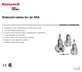
Figure 3.1 Example of an AS-Interface system with safety module and emergency-stop button
The module is suitable for the decentralized connection of switches in very confined spaces.
The connection to the AS-Interface cable and the connection of the inputs and the output(s)
involves bare cable ends.
Each channel has an LED mounted on the top side of the module to indicate the current switch
state. There is an LED for monitoring AS-Interface communication and for indicating that the
module has the address 0. In the event of a communication failure, the outputs are discon-
nected from the power supply. .
3.2 Slave Profile
The modules have the following profile:
The data value is transmitted as defined by AS-Interface profile 7.B.
System Overview
+ -
+ - + - Shield
brown bluebrownblue
AS-i
ok
12
Release circuit
Power supply Gateway/safety monitor G10 safety module Stack light
Emergency-stop button with
volt-free contacts
VAA-2E1A-CB10-SJ/E2J-FL VAA-2E2A-CB10-SJ/E2J-FL
I/O = 7 7
ID = B B
ID2 = 0 0
ID1 = F (programmable) F (programmable)

2019-12
10
VAA-2E1A-CB10-SJ/E2J-FL, VAA-2E2A-CB10-SJ/E2J-FL
Product Description
3.3 Indicators and Operating Elements
Figure 3.2 VAA-2E1A-CB10-SJ/E2J-FL
Figure 3.3 VAA-2E2A-CB10-SJ/E2J-FL
Indicators
PWR AS-Interface status indicator
FAULT Fault indicator
IN1, IN2 Input switch state
OUT1 Output switch state
PWR AS-Interface status indicator
FAULT Fault indicator
IN1, IN2 Input switch state
OUT1,
OUT2
Output switch state
Designation Description
PWR AS-Interface voltage; green LED
Green: voltage OK
Green flashing: address 0
FAULT Fault indication; red LED
Red: communication error or address is 0
Red flashing: output overload
IN1
IN2
Switch state (input); 2 yellow LEDs
OUT1
OUT2
Switch state (output); 1 or 2 yellow LEDs
LED
PWR
FAULT
IN 1
IN 2
OUT 1
AS-i+
AS-i-
I1+
I2+
I1-
I2-
O1+
O1-
AS-Interface:
IN:
OUT:
BN =
BU =
BK =
GY =
YE =
WH =
GN =
PK =
LED
PWR
FAULT
IN 1
IN 2
OUT 1
OUT 2
AS-i+
AS-i-
I1+
I2+
I1-
I2-
O1+
O2+
O1-
O2-
AS-Interface:
IN:
OUT:
BN =
BU =
BK =
GY =
YE =
WH =
GN =
OG =
PK =
VT =

VAA-2E1A-CB10-SJ/E2J-FL, VAA-2E2A-CB10-SJ/E2J-FL
Product Description
2019-12
11
3.4 Connections
Figure 3.4 VAA-2E1A-CB10-SJ/E2J-FL
Safety-Related Inputs
Conventional (Non-Safe) Electronic Output
Figure 3.5 VAA-2E2A-CB10-SJ/E2J-FL
Safety-Related Inputs
VAA-2E1A-CB10-SJ/E2J-FL Connections
Color Designation Description
Brown (BN) AS-i + AS-Interface +
Blue (BU) AS-i - AS-Interface -
Black (BK) I1+ Mechanical switch 1 +
Gray (GY) I2+ Mechanical switch 2 +
Yellow (YE) I1- Mechanical switch 1 -
White (WH) I2- Mechanical switch 2 -
Color Designation Description
Green (GN) O1+ Output 1 +
Pink (PK) O1- Output 1 -
VAA-2E2A-CB10-SJ/E2J-FL Connections
Color Designation Description
Brown (BN) AS-i + AS-Interface +
Blue (BU) AS-i - AS-Interface -
LED
PWR
FAULT
IN 1
IN 2
OUT 1
AS-i+
AS-i-
I1+
I2+
I1-
I2-
O1+
O1-
AS-Interface:
IN:
OUT:
BN =
BU =
BK =
GY =
YE =
WH =
GN =
PK =
LED
PWR
FAULT
IN 1
IN 2
OUT 1
OUT 2
AS-i+
AS-i-
I1+
I2+
I1-
I2-
O1+
O2+
O1-
O2-
AS-Interface:
IN:
OUT:
BN =
BU =
BK =
GY =
YE =
WH =
GN =
OG =
PK =
VT =

2019-12
12
VAA-2E1A-CB10-SJ/E2J-FL, VAA-2E2A-CB10-SJ/E2J-FL
Product Description
Conventional (Non-Safe) Electronic Output
3.5 Operating Principle
3.5.1 Safety-Related Inputs
The module generates an internal code sequence. This code sequence is monitored by a
safety monitor (additional node) to ensure the correct order.
Figure 3.6 Code generation
The status of the externally connected mechanical switches influences the code sequence
transmission.
Information regarding the activation of the connected mechanical switches (e.g., if the emer-
gency-stop button is pressed, code transmission is interrupted) is transmitted as follows:
Black (BK) I1+ Mechanical switch 1 +
Gray (GY) I2+ Mechanical switch 2 +
Yellow (YE) I1- Mechanical switch 1 -
White (WH) I2- Mechanical switch 2 -
Color Designation Description
Green (GN) O1+ Output 1 +
Orange (OG) O2+ Output 2 +
Pink (PK) O1- Output 1 -
Violet (VT) O2- Output 2 -
Color Designation Description
Activated input channel
Code bit
3 2 1 0
1 X X 0 0
2 0 0 X X
1 and 2 0 0 0 0
None X X X X
1
1. Operating condition
Table 3.1
DI1
DI0
DI2
DI3
S1
S2
AS-i Bus
AS-i Chip
Strobe
Code-
Generator

VAA-2E1A-CB10-SJ/E2J-FL, VAA-2E2A-CB10-SJ/E2J-FL
Product Description
2019-12
13
The code words 0000, XX00, and 00XX prompt the safety monitor to put the plant in a safe
state (for instance using the emergency-stop button), without reporting a fault. If a code word
bit differs from the target code word, the safety monitor will switch the plant to a safe state and
will indicate a slave fault.
The two input channels on the safety module are independent. The safety monitor can be
parameterized to monitor the synchronicity of both inputs for dual-channel applications.
3.5.2 Cross Circuit Monitoring of Inputs
The inputs are monitored for cross circuits. The cross circuit monitoring function is able to
detect low-ohm cross circuits caused by a metallic connection between the two inputs.
3.6 Scope of Delivery
The scope of delivery includes:
•Safety module
•Documentation

2019-12
14
VAA-2E1A-CB10-SJ/E2J-FL, VAA-2E2A-CB10-SJ/E2J-FL
Installation
4 Installation
4.1 Mounting
You can attach the device to a flat mounting surface using the supplied double-sided adhesive
tape.
Figure 4.1
Caution!
Mechanical damage
Protect the device against mechanical damage.
Do not mount the device in an exposed location.
Install the device in a switch cabinet or switch box with a degree of protection of at least IP54.
VAA-2E1A-CB10-SJ/E2J-FL
36
39.5
2.1
10.1
4

VAA-2E1A-CB10-SJ/E2J-FL, VAA-2E2A-CB10-SJ/E2J-FL
Installation
2019-12
15
Figure 4.2
4.2 Connecting Inputs and Outputs
VAA-2E2A-CB10-SJ/E2J-FL
36
39.5
2.1
10.1
4
Warning!
Electrical short caused by moisture
If the surrounding enclosure or switch cabinet is not properly sealed, the safety function may be
lost.
Note
If you are connecting just one single-channel switch, use input 1. In this case, you must bridge
input 2.
You can connect only one mechanical switch per channel. If you connect a two-channel switch,
you must use both channels.

2019-12
16
VAA-2E1A-CB10-SJ/E2J-FL, VAA-2E2A-CB10-SJ/E2J-FL
Installation
Figure 4.3 VAA-2E1A-CB10-SJ/E2J-FL connection
Figure 4.4 VAA-2E2A-CB10-SJ/E2J-FL connection
Caution!
Short circuit
If you are not using an available output, make sure that the bare cable end is insulated. Bare
cable ends can be protected by fitting a terminal block, for example.

VAA-2E1A-CB10-SJ/E2J-FL, VAA-2E2A-CB10-SJ/E2J-FL
Commissioning
2019-12
17
5 Commissioning
5.1 Configuring the AS-Interface Safety Monitor
For details of necessary organizational measures affecting configuration of the safety monitor,
please refer to the documentation for the safety monitor.
Safety Classification
The module contains two independent, redundant input channels. If both input channels are
used, the module is suitable for use up to category 4/PL e in accordance with ISO 13849-1, or
SIL 3 in accordance with EN/IEC 61508 and EN/IEC 62061. In this case, the monitor must be
programmed so that dual-channel switching is monitored.
If a single-channel switch is used, the module is suitable for use up to category 2/PL c in accor-
dance with ISO 13849-1, or SIL 1 in accordance with EN/IEC 61508 and EN/IEC 62061. Only
tested and certified power supplies with safe isolation may be used to supply power. These
power supplies must have PELV voltage in accordance with EN 50295/IEC 62026-2, and a
minimum MTBF of 50 years. The power supplies are designed to exclude a short circuit
between the primary and secondary sides.
5.2 Assigning an Address to the Module
Assign an address to the module using a handheld or an AS-Interface master. You can assign
addresses from 1 to 31. The default safety module address is 0.
5.3 Operational Testing
Perform function tests as part of the installation by activating the safety function. The opera-
tional test uncovers all existing faults at the time of installation. Because the safe inputs are
monitored for crossed circuits, it is not necessary to test for short circuits in the cabling.
Performing a Function Test
1.
Activate the safety function by interrupting the input. This can be done by actuating a
connected mechanical switch or on the cable.
2.
Check whether the safety monitor detects the interruption without issuing a fault message.
3.
Stop the interruption on the input on the connected mechanical switch or on the cable.
4.
Enable the input on the safety monitor.
5.4 Operating Mode
No operating modes can be activated for the inputs.
Note
In the case of single-channel safety functions, test the function for each channel.
For applications of category 4/PL e in accordance with ISO 13849-1 or SIL 3 in accordance
with EN/IEC 61508 and EN/IEC 62061, the two inputs must be monitored using the safety
monitor to ensure that they are synchronous.

2019-12
18
VAA-2E1A-CB10-SJ/E2J-FL, VAA-2E2A-CB10-SJ/E2J-FL
Operation
6 Operation
Programming the safety monitor parameters defines the safety function of the device. Read the
corresponding documentation.
6.1 Safety-Related Inputs
The module generates an internal code sequence. This sequence is monitored by a safety
monitor (additional bus device) to ensure the correct order.
The status of the externally connected mechanical switches controls the code sequence trans-
mission. To ensure the safe state of the device, use switches with a safety function with positive
opening operation. The code sequence is interrupted by actuating the switch.
The two input channels on the safety module are independent. The safety monitor must be
parameterized to monitor that the two inputs are synchronous for dual-channel applications of
category 4/PL e as per ISO 13849-1 or SIL 3 as per EN/IEC 62061.
6.2 Conventional (Non-Safe) Electronic Outputs
The outputs are designed in line with the AS-Interface standard. Positive potential (PNP tech-
nology) is switched for these outputs.
•The output is controlled directly by data bits D0 and D1 of the AS-Interface master.
Communication monitoring:
•In the event of a communication failure, the outputs are disconnected from the power
supply.
•Do not use the conventional output for safety functions.
•Make sure that the individual cable ends of the connection lines do not touch each other.

VAA-2E1A-CB10-SJ/E2J-FL, VAA-2E2A-CB10-SJ/E2J-FL
Servicing
2019-12
19
7 Servicing
Regular function tests may be necessary, depending on the safety category.
Performing a Function Test
1.
Activate the safety function by actuating a connected mechanical switch and thus interrupting
the input.
2.
Check whether the safety monitor detects the interruption without issuing a fault message.
3.
End the interruption at the input created by the connected mechanical switch.
4.
Enable the input on the safety monitor.
Note
In the case of single-channel safety functions, test the function for each channel.

2019-12
20
VAA-2E1A-CB10-SJ/E2J-FL, VAA-2E2A-CB10-SJ/E2J-FL
Troubleshooting
8 Troubleshooting
Source of Fault Possible Cause Remedy
The safety monitor puts the
plant into a safe state and
reports a malfunction.
•There is a crossed circuit at
one of the inputs.
•There is electromagnetic
interference in the lines.
Check the line and repair if necessary.
If none of the lines are damaged, send the
device to Pepperl+Fuchs for repair.
The safety monitor acts like an
emergency-stop mechanism
without an emergency-stop
mechanism switch having been
activated.
The line on one of the inputs is
defective or not connected cor-
rectly.
Check the line and repair if necessary.
Check that the connections are seated cor-
rectly.
/