Page is loading ...

3M Occupational Health and Environmental Safety
Fall Protection Equipment
User Instructions for 3M
TM
Self Retracting Lanyards
Important: Keep these User Instructions for reference.
Self Retracting
User Instructions
Lanyards

1. Compliant fall protection and emergency rescue systems help prevent serious injury
during fall arrest. Users must read and understand the User Instructions provided with
the product and be properly trained by their employer prior to use per OSHA 29 CFR
1910.66 and 1926.503 or applicable local standards. Misuse or failure to follow warnings
and instructions may result in serious personal injury or death. For proper use, see
supervisor, User Instructions, or call Technical Service at 800-243-4630.
2. Failure to follow all instructions and limitations on the use of Self Retracting Lanyards may
result in serious personal injury or death.
3. Minors, pregnant women and anyone with a history of either back or neck problems should
not use this equipment.
4. Self Retracting Lanyards, including those with Rescue Capability, are designed for a single
user.
5. Not all fall protection components are rated for the same user weight capacity. Users must be
within each component’s capacity range.
6. Before using a personal fall arrest system, employees must be trained in accordance with the
requirements of OSHA 29 CFR 1910.66 in the safe use of the system and its components.
7. Personal fall arrest systems, including Self Retracting Lanyards, must be inspected prior
to each use for wear, damage, and other deterioration, and defective components must be
immediately removed from service in accordance with the requirements of OSHA 29 CFR
1910.66 and 1926.502.
8. Do not use or install equipment without proper training from a “competent person” as defi ned
by OSHA 29 CFR 1926.32(f).
9. Caution must be taken when using Self Retracting Lanyards near moving machinery,
electrical hazards, sharp edges, or abrasive surfaces. Contact with these elements may cause
equipment failure, personal injury, or death.
10. Do not expose Self Retracting Lanyards to chemicals or harsh solutions which may have a
harmful effect. Contact 3M Technical Service with any questions.
11. Users must perform a locking test on Self Retracting Lanyards before each use by pulling
smoothly on the lanyard, then pulling sharply on the lanyard to engage the locking
mechanism. Remove from service if the locking mechanism does not lock.
12. Striking objects horizontally due to the pendulum affect of a swing fall may cause serious
injury or death.
13. Never attach the unused leg of the Dual Leg Retractable back to the harness at any location
other than an approved lanyard storage keeper.
14. Self Retracting Lanyards are designed to be used in temperatures ranging from -40ºF to
+130ºF (-40°C to +54°C).
15. The addition of the 3M 3012 Personal Energy Absorber may increase the clearance
requirements by 3½ feet (1.07 m). The additional distance must be taken into consideration
during the clearance calculation process.
GENERAL SAFETY INFORMATION
Under Penalty of Law
These User Instructions are not to be removed except by the user of this equipment. Current
User Instructions must always be available to the user.
WARNING
2

16. Never allow slack in the cable of a Self Retracting Lanyard while in rescue mode.
17. Never use combinations of components or subsystems that may affect, or interfere with the
safe function of each other. If you do not know if combinations of components or subsystems
may affect the safety function of each other, contact Technical Services at 800-243-4630.
18. Store Self Retracting Lanyards in a cool, dry, clean environment, out of direct sunlight, when
not in use.
19. After a fall occurs, or if any part of the load indicator warning is showing, the Self Retracting
Lanyard must be immediately removed from service for authorized repairs or disposal.
20. If inspection reveals any defect, inadequate maintenance, or unsafe condition, immediately
remove from service for authorized repairs or disposal.
21. Only 3M, or persons or entities authorized in writing by 3M, shall make repairs or alterations
to the equipment.
22. Alterations or misuse may result in serious personal injury or death.
3
Anchorage
An anchorage, as defi ned by OSHA 29 CFR 1926.502 “shall be independent of any anchorage
being used to support or suspend platforms and capable of supporting at least 5,000 pounds
(22.2 kN) per employee attached, or shall be designed, installed, and used as follows: as part of a
complete personal fall arrest system which maintains a safety factor of at least two; and under the
supervision of a qualifi ed person.”
Body Support
A body support is the component of a personal fall arrest system that is worn on or around the
body. Per OSHA 29 CFR 1926.502 effective January 1, 1998, body belts are not acceptable as
part of a personal fall arrest system. Note: The use of a body belt in a positioning device system
is acceptable. Full body harnesses must be used for all fall arrest systems.
Connecting Devices
A connecting method is the link between the body support and anchorage. Connecting methods
will vary depending on the application.
CAUTION
FALL ARREST SYSTEM COMPONENTS
System Components
A complete fall arrest system consists of the following components: Anchorage, Body Support,
and Connecting Devices. Note: For continuous protection, more than one system may be
needed.
1. If a Self Retracting Lanyard is used in conjunction with a cross-arm strap anchorage
connector, other anchorage extension, or horizontal lifeline, the additional length of the
anchorage connector, or sag from the lifeline must be taken into consideration during the
clearance calculation process.
2. Wear proper Personal Protective Equipment when performing Inspection, Cleaning and
Maintenance procedures. Safety glasses & gloves are recommended.

4
Anchorages
All anchorages to which the Self Retracting Lanyards attach must meet the requirements of
OSHA 29 CFR 1910.66 and ANSI Z359.1-2007. OSHA states:
Anchorages to which personal fall arrest equipment is attached shall be capable of supporting
at least 5,000 pounds (22.2 kN) per employee attached, or shall be designed, installed, and used
as part of a complete personal fall arrest system which maintains a safety factor of at least two,
under the supervision of a qualifi ed person.
ANSI Z359.1-2007 states that anchorages in a personal fall arrest system must have a strength
capable of sustaining static loads, applied in all permitted directions by the system, of at least:
(a) two times the maximum arrest force permitted on the system when certifi cation exists, or
(b) 5,000 pounds (22.2 kN) in the absence of certifi cation.
The strength in (a) and (b) must be multiplied by the number of personal fall arrest systems
attached to the anchorage, when more then one personal fall arrest system is attached to the
anchorage.
ANCHORAGE REQUIREMENTS
Use Limitations
1. Self Retracting Lanyards, including those with Rescue Capability, are designed for a single
user with a capacity up to 310 lb (141 kg) or 400 lb (181 kg) including clothing, tools, etc.
See individual product label for capacity ratings.
2. Self Retracting Lanyards shall only be used as part of a personal fall arrest system that limits
the maximum free fall distance to 2 feet (0.6 m). If used with 3M 3012 Personal Energy
Absorber, the Self Retracting Lanyard may be used in leading edge applications with free
falls exceeding 2 feet (0.6 m) up to a maximum of 6 feet (1.8 m) with a 310 lb (141 kg) user
capacity.
3. Self Retracting Lanyards must be used with a full body harness.
4. Do not allow the line constituent to retract into the unit in an uncontrolled manner.
Use Instructions
1. The complete fall protection system must be planned (including all components, calculating
fall clearance, and swing fall) before using.
2. Users must have a rescue plan, and the means at hand to implement it, that provides for the
prompt rescue of employees in the event of a fall, or assures that employees are able to rescue
themselves.
Important
Before use, the user must read and understand these User Instructions. Keep these User
Instructions for reference.
USE INSTRUCTIONS AND LIMITATIONS
Purpose
3M Self Retracting Lanyards (SRL’s) are for individual use and designed to be used as part of a
personal fall arrest system, to help limit the fall arrest forces in the event of a fall.

5
Anchorage Connectors
Anchorage connectors are components that couple the personal fall arrest system to the
anchorage. In accordance with ANSI Z359.1-2007, the anchorage connector must be capable of
withstanding (without breaking) a 5,000 lb (22.2 kN) load, and able to withstand a 3,600 lb
(16 kN) load without cracking, or permanent deformation visible to the unaided eye.
The strength of all anchorage connectors must be multiplied by the maximum number of
personal fall arrest systems attached.
A mobile anchorage connector should be used to provide lateral mobility, and help prevent
the
possibility of a swing fall.
Anchorages should be located as vertically as possible above the user’s head and be positioned as
not to exceed the maximum allowable free fall for the system.
CONNECTION REQUIREMENTS
Snaphooks and Carabiners
Snaphooks and carabiners used on Self Retracting Lanyards, marked with the ANSI Z359.1-07
or ANSI Z359.12-09 standard, are self-locking with a minimal tensile break strength of 5,000 lb,
and a 3,600 lb gate rating.
Self Retracting Lanyards with hardware marked to the ANSI Z359.1-1999 and/or CSA Z259.12-
01 standards, incorporate self-locking snaphooks and carabiners with minimal tensile break
strength of 5,000 lb, a minimum gate rating of 220 lb, and a minimum side load gate rating of
350 lb.
Compatibility Limitations
All connecting subsystems must only be coupled to compatible connectors. OSHA 29 CFR
1926.502 prohibits snaphooks from being engaged to certain objects unless two requirements
are met: snaphook must be a locking type and must be “designed for” making such a connection.
“Designed for” means that the manufacturer of the snaphook specifi cally designed the snaphook
to be used to connect to the equipment in question. The following connections must be avoided,
because they can result in rollout* when a nonlocking snaphook is used:
• Direct connection of a snaphook to horizontal lifeline.
• Two (or more) snaphooks connected to one D-ring.
• Two snaphooks connected to each other.
• A snaphook connected back on its integral lanyard.
• A snaphook connected to a webbing loop or webbing lanyard.
• Improper dimensions of the D-ring, rebar, or other connection point in relation to
the snaphook dimensions that would allow the snaphook keeper to be depressed
by a turning motion of the snaphook.
*Rollout: A process by which a snaphook or carabiner unintentionally disengages from another
connector or object to which it is coupled. (ANSI Z359.0-2007)
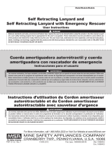
Clearance Requirements
The following illustration is an example of how to calculate the fall clearance requirements

6
using a Self Retracting Lanyard connected to the dorsal D-ring of a full body harness. Add the
deceleration distance identifi ed on the label of the Self Retracting Lanyard (3½ feet per OSHA
1910 & 1926) to the slide of the D-ring (1 foot) and the additional safety clearance (2 feet), to
allow for the possibility of an improperly fi t harness and/or a miscalculation of distances. A total
6½ feet of fall clearance is required for this example.
Caution: If a Self Retracting Lanyard is used in conjunction with a cross-arm
anchorage connector, other anchorage extension, horizontal lifeline, or extended D-ring, the
additional length of the anchorage connector, extended D-ring, or sag from the lifeline must
be taken into consideration during the clearance calculation process.
Warning: The addition of the 2 foot (0.6 m) 3M 3012 Personal Energy Absorber will
increase the clearance requirements by 5½ feet (1.6 m). The additional distance must be
taken into consideration during the clearance calculation process.
Swing Falls
To minimize the possibility of a swing fall, work as directly under the anchorage connector as
possible.
Warning: Striking objects horizontally due to the pendulum affect of a swing fall may
cause serious injury or death.
Swing falls also increase the vertical fall distance of a worker, compared to a fall directly below
the anchorage connector. Swing falls may be reduced by using overhead anchorage connectors
that move with the worker.
½
½
½

7
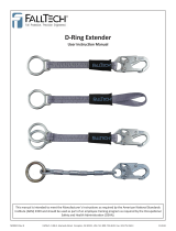
Free Fall
Maximum allowable free fall for a Self Retracting Lanyard is 2 feet.
The free fall distance with a Self Retracting Lanyard connected to the dorsal D-ring of a full
body harness and an anchorage connector above the workers head, Worker (a), is always zero.
To calculate the free fall distance of a Self Retracting Lanyard connected to the dorsal D-ring of
a full body harness to an anchorage connector below the workers dorsal D-ring, Worker (b), add
the distance from the dorsal D-ring to the anchorage connector (1 foot) to the length of the fully
retracted Self Retracting Lanyard from connector to connector (2 feet). The free fall for worker
(b) is 3 feet.
The free fall distance using a Self Retracting Lanyard connected to the dorsal D-ring of a full
body harness and an anchorage connector that is on the walking/working surface, Worker (c),
add the distance from D-ring on the harness to the walking/working surface (5 feet) to the length
of the fully retracted Self Retracting Lanyard from connector to connector (2 feet). The free fall
for worker (c) is 7 feet.
OPERATION
Before Each Use
Users of personal fall arrest systems must have a rescue plan in place, if the users cannot rescue
themselves, as well as the means to carry out the rescue.
Self Retracting Lanyards must be inspected prior to each use for wear, damage, and other
deterioration. Check the operation by pulling smoothly on the lanyard, then pull sharply on the
lanyard to engage the locking mechanism. All snaphooks and carabiners on the product must
be able to self-close and lock. All webbing must be inspected for tears, cuts, fraying, abrasion,
discoloration, or other signs of wear and damage. Sewn terminations should be secure, complete,
and not visibly damaged. Cable must be inspected for kinks, broken strands, corrosion, abrasion,
or other signs of wear and damage. Swaged terminations should be secure with the thimble tight
and not visibly damaged. Load indicator must not be deployed. Damaged and other deteriorated
and defective components must be immediately removed from service, in accordance with the
requirements of OSHA 29 CFR 1910.66 and 1926.502.

8
Overhead Anchorage
Attach the housing connector of the Self Retracting Lanyard to the anchorage or anchorage
connector. The opposing end is connected to the dorsal D-ring of the full body harness. Never
attach an additional energy absorbing lanyard, Self Retracting Lanyard, or similar component to
lengthen the lifeline.
Warning:
Never use combinations of components or subsystems that may affect,
or interfere with the safe function of each other. If you do not know if combinations of
components or subsystems may affect the safety function of each other, contact Technical
Services at 800-243-4630.
CONNECTION
Housing to Harness
Lighter weight Self Retracting Lanyards (15 feet or less) may attach the housing connector
directly to the dorsal D-ring of the full body harness. Heavier weight Self Retracting Lanyards
(greater than 15 feet) are not recommended for this application. The opposing end is connected
to the anchorage or anchorage connector.
Dual Leg Retractable to Full Body Harness
Attach the Dual Leg Yoke directly to the dorsal D-Ring of the full body harness using supplied
carabiner. Attach one leg of the Dual Leg Retractable to the anchorage or anchorage connector,
and the unused leg to an approved lanyard storage keeper on the harness.
Warning: Never attach the unused leg of the Dual Leg Retractable back to the harness
at any location other than an approved lanyard storage keeper.
When using the Dual Leg Retractable to move between fall protection systems, attach the unused
leg to the new location before disconnecting the fi rst leg. Connection of both legs to separate
anchorages or anchorage connectors while transitioning between systems, is acceptable.
Rescue Mode
To engage the rescue mode on the 205G 3-Way Retractable, pull out the hand grip on the arm.
Pull button on the bottom of the housing while pulling arm away from the unit until arm clicks in
place. This will engage the rescue mode of the 205G 3-Way Retractable.
Warning: Never allow slack in cable while in rescue mode.
Wind cable completely into housing before stowing arm. To stow arm and return to SRL mode,
pull button on the bottom of the housing while pushing arm towards the unit. Pull hand grip on
the arm out and collapse hand grip parallel to the arm. Attach strap to secure arm in place.
Leading Edge Applications
The use of the 3M 3012 Personal Energy Absorber is required in leading edge applications. The
3012 Personal Energy Absorber must be placed inline with the Self Retracting Lanyard to add
energy absorption properties at the body end of the system. The additional energy absorption
properties will keep forces below the cable sheer strength in the event of a fall over leading edge.
For Self Retracting Lanyards with an integral external shock pack with the housing connected
to the dorsal D-ring of the full body harness; connect the snaphook of the 3012 Personal Energy

9
Absorber to the dorsal D-ring of the full body harness. Attach the housing connector of the Self
Retracting Lanyard directly to the D-Ring of the 3012 Personal Energy Absorber. The snaphook
of the Self Retracting Lanyard is connected to the anchorage or anchorage connector.
For Self Retracting Lanyards with an integral external shock pack with the housing connected
to the anchorage or anchorage connector; attach the snaphook of the 3012 Personal Energy
Absorber to the anchorage or anchorage connector. Connect the housing connector of the Self
Retracting Lanyard directly to the D-Ring of the 3012 Personal Energy Absorber. The snaphook
of the Self Retracting Lanyard is then connected to the dorsal D-ring of the full body harness.
Self Retracting Lanyards with an integral external shock pack, with the shock pack connected to
the dorsal D-ring of the full body harness, does not require the 3012 Personal Energy Absorber
when used with 3M pre-engineered fl exible horizontal lifeline systems.
Warning: The addition of the 3M 3012 Personal Energy Absorber may increase the
clearance requirements by 3½ feet (1.07 m). The additional distance must be taken into
consideration during the clearance calculation process.
For Self Retracting Lanyards without an integral external shock pack with the housing connected
to the anchorage or anchorage connector; attach the housing connector to the anchorage or
anchorage connector. Connect the snaphook of the Self Retracting Lanyard to the D-ring of the
3012 Personal Energy Absorber. The snaphook of the 3012 Personal Energy Absorber is then
connected to the dorsal D-ring of the full body harness.
For Self Retracting Lanyards without an integral external shock pack with the housing connected
to the dorsal D-ring of the full body harness; attach the housing connector directly to the dorsal
D-ring of the full body harness. Attach the snaphook of the Self Retracting Lanyard to the
D-Ring of the 3012 Personal Energy Absorber. The snaphook of the 3012 Personal Energy
Absorber is connected to the anchorage or anchorage connector.
Lighter weight Self Retracting Lanyards (15 feet or less) without integral an external shock pack,
with the housing connected directly to the dorsal D-ring of the full body harness, does not require
the 3012 Personal Energy Absorber when used with 3M pre-engineered fl exible horizontal
lifeline systems.
MATERIALS
Hardware
Snaphooks and carabiners on the Self Retracting Lanyards marked with the ANSI Z359.1-07 or
ANSI Z359.12-09 standard, are self-locking with a minimal tensile break strength of 5,000 lb,
and a 3,600 lb gate rating.
Self Retracting Lanyards with snaphooks and carabiners marked to the ANSI Z359.1-1999
PERFORMANCE
Dynamic
Self Retracting Lanyards when dynamically tested in accordance with the requirements of the
ANSI Z359.1-2007 standard have a maximum arrest force of 900 lbf (4 kN) and a maximum
elongation of 42 inches (1067 mm).

10
standard, incorporate self-locking snaphooks and carabiners with minimal tensile break strength
of 5,000 lb, a minimum gate rating of 220 lb, and a minimum side load gate rating of 350 lb.
INSPECTION
Frequency
All Self Retracting Lanyards must be inspected prior to each use, and annually by an OSHA
defi ned “competent person” other than the user. Local, state, governmental and jurisdictional
agencies may require the user to conduct more frequent or mandatory inspections.
Criteria
Warning: If inspection reveals any defect, inadequate maintenance, or unsafe condition,
immediately remove from service for authorized repairs or disposal.
Warning: Any equipment that has been subjected to the forces of arresting a fall or
has a deployed load indicator must be immediately removed from service for authorized
repairs or disposal. See product label for specifi c load indicator warning.
All components of the Self Retracting Lanyard must be inspected.
Housing or casing must be free from cracks, distortion or any other damage.
Check the operation of the unit by pulling smoothly on the lanyard, then pull sharply on the
lanyard to engage the locking mechanism. Unit must not slip when locked.
All markings must be legible and attached to the product.
All snaphooks and carabiners on product must be able to self-close and lock. All hardware must
be free of cracks, sharp edges, deformation, corrosion, or any evidence of defect.
Housing
The REW-7 ReLoad, MS-11, and 3307 Self Retracting Lanyards have an aluminum casing.
The REW and REC ReLoad series incorporate an impact modifi ed nylon case.
M-Series and 3-Way Units uses an aluminum alloy housing.
RLD-Series and MS-Series utilize a polymer housing.
Line Constituent
The REW-5 and REW-7 ReLoad™ Self Retracting Lanyards utilize a ⁄ inch (1.3 mm) by ⁄
inch (20 mm) polyester webbing with Vectran™ core.
The REW-12 and REW-23 ReLoads incorporate a ⁄inch (2.4 mm) by 1 inch (25 mm) polyester
webbing.
The MS-Series including the 3307 has a ⁄inch (1.3 mm) by 1 inch (25 mm) Dyneema®
webbing.
The REC ReLoad series use ⁄inch (4.8 mm) (7x19) galvanized or stainless steel cable.
M-Series, RLD-Series and 3-Way Units use ⁄ inch (4.8 mm) (7x19) galvanized cable.

11
The lanyard must fully extract and retract smoothly without any slack being created upon
retraction.
To inspect webbing, bend a portion of the webbing 6-8 inches into an upsidedown ‘U’ shape.
Continue along all webbing inspecting for tears, cuts, fraying, abrasion, discoloration, burns,
holes, mold, pulled or broken stitches, or other signs of wear and damage.
Sewn terminations must be secure, complete, and not visibly damaged.
Cable must be inspected for kinks, broken strands, corrosion, abrasion, or other signs of wear and
damage. Swaged terminations must be secure with the thimble tight, and not visibly damaged.
CLEANING, MAINTENANCE, STORAGE
Caution: Wear proper Personal Protective Equipment when performing Inspection,
Cleaning and Maintenance procedures. Safety glasses & gloves are recommended.
Cleaning
The Self Retracting Lanyard can be wiped down with a mild detergent and clean water solution,
and rinsed with a dampened clean cloth to remove detergent. The hardware can also be wiped
down to remove grease, or dirt with a clean dry cloth.
Storage
Self Retracting Lanyards should be stored in a cool, dry place out of direct sunlight. Do not store
in areas where damage from environmental factors such as heat, light, excessive moisture, oil,
chemicals and their vapors, or other degrading elements may be present. Do not store damaged
equipment or equipment in need of maintenance in the same area as product approved for use.
Equipment that has been stored for an extended period must be inspected as defi ned in these
User Instructions prior to use.
Maintenance
Self Retracting Lanyards requiring maintenance must be tagged “unusable” and removed
from service.
Warning: Only 3M, or persons or entities authorized in writing by 3M, shall make
repairs or alterations to the equipment.
Cleaning and maintenance may be performed by the user.
Snaphooks and carabiners may require periodic lubrication. Do not apply oil, grease, or other
contaminates on the lanyard. Use a dry lubricant that has proper resistance to temperature
extremes, moisture, and corrosion. Do not over-lubricate.
LABELING
All labeling must be legible and attached to the Self Retracting Lanyard.

12
Product Label
Warning Label
Warning Label
Product Label

13
Warning Label
Product Label
Warning Label
WiLbl
Product Label

14
Operation Label
Arm Label
Product Label
Warning Label

15
Product Label
Warning Label
Product and Warning Label
g
MODELS AND PART NUMBERS lanyard length in feet
Self Retracting Lanyards - Web Units - 310 lb capacity
ReLoad - REW-5 (5), REW-5-0241A (5), REW-7 (7), REW-7-0241A (7) REW-12 (12),
REW-23 (23)
MS-Series - 3307 (7), 3307-0241 (7), 3307-0241A (7), MS-11 (11), MS-11/0241 (11),
MS-16 (16), MS-20 (20), MS-30 (30), MS-50 (50)
Self Retracting Lanyards - Cable Units
ReLoad - 400 lb capacity - REC-23 (23), REC-23-SS (23), REC-30 (30), REC-30-SS (30),
REC-40 (40), REC-40-SS (40), REC-50 (50), REC-50-SS (50)
RLD-Series - 310 lb capacity - RLD-10 (10), RLD-10-0241 (10), RLD-10S (10), RLD-20
(20), RLD-20NIH (20),RLD-30 (30), RLD-30NIH (30), RLD-50 (50)
M-Series - 310 lb capacity - M-15 (15), M-30 (30), M-40 (40), M-40NIH (40), M-50 (50),
M-75 (75), M-100 (100), M-130 (130)
Self Retracting Lanyards with Rescue Capability - 310 lb capacity
3-Way Units - 205G-50 (50), 205G-75 (75), 205G-100 (100)

16
Please recycle. Printed in USA.
© 3M 2012
3M and ReLoad are trademarks of 3M
Company, used under license in Canada.
Vectran is a trademark of Kuraray Co., Ltd.
Dyneema is a trademark of Royal DSM.
All rights reserved.
IM-0002F (04-2012) 34-8709-8544-6
ISO 9001
FM 573368
3M Occupational Health and
Environmental Safety Division
3M Center Building 235-2W-70
Saint Paul, MN 55144-1000
USA
Technical Assistance:
800-243-4630 in U.S.
800-267-4414 in Canada
www.3M.com/FallProtection
www.3M.com/PPESafety
Product Warranty, Limited Remedy, and
Limitation of Liability
WARRANTY: THE FOLLOWING IS MADE IN LIEU OF ALL WARRANTIES OR
CONDITIONS, EXPRESS OR IMPLIED, INCLUDING THE IMPLIED WARRANTIES OR
CONDITIONS OF MERCHANTABILITY OR FITNESS FOR A PARTICULAR PURPOSE.
Equipment offered by 3M is warranted against factory defects in workmanship and materials for a
period of one year from date of installation or fi rst use by the original owner.
LIMITED REMEDY: Upon notice in writing, 3M will repair or replace all defective items at
3M’s sole discretion. 3M reserves the right to require that the defective item be returned to its
plant for inspection before determining the appropriate course of action. Warranty does not cover
equipment damage resulting from wear, abuse, damage in transit, failure to maintain the product
or other damage beyond the control of 3M. 3M shall be the sole judge of product condition
and warranty options. This warranty applies only to original purchaser and is the only warranty
applicable to this product. Please contact 3M technical service department at 800-243-4630 for
assistance.
LIMITATION OF LIABILITY: IN NO EVENT WILL 3M BE LIABLE FOR ANY
INDIRECT, INCIDENTAL, SPECIAL OR CONSEQUENTIAL DAMAGES INCLUDING,
BUT NOT LIMITED TO LOSS OF PROFITS, IN ANY WAY RELATED TO THE PRODUCTS
REGARDLESS OF THE LEGAL THEORY ASSERTED.
/