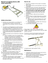
INTRODUCTION
To the owner or user: The service manual you
are reading is intended to provide you, and the
maintenance or service technician, with the
information needed to install, start up, clean,
maintain, and service this ice system.
The NM950 is a modular ice system that fits a
variety of Scotsman ice storage bins.
It features: front service for the freezer,
gearmotor, control box, water reservoir, and
bin control; an electronic circuit for monitoring
ice and water level; a thermostatic expansion
valve; and R-502 as the refrigerant.
TABLE OF CONTENTS
Installation
For the Installer
Specifications . . . . . . . . . . . . . . . . . . . . . . . . . . . . . . . . . . . 2
Location . . . . . . . . . . . . . . . . . . . . . . . . . . . . . . . . . . . . . . 4
Two units on one bin . . . . . . . . . . . . . . . . . . . . . . . . . . . . . . . 5
For the Plumber . . . . . . . . . . . . . . . . . . . . . . . . . . . . . . . . . . . . . . 6
For the Electrician . . . . . . . . . . . . . . . . . . . . . . . . . . . . . . . . . . . . . 7
Final Check List . . . . . . . . . . . . . . . . . . . . . . . . . . . . . . . . . . . . . . 8
Start Up . . . . . . . . . . . . . . . . . . . . . . . . . . . . . . . . . . . . . . . . . . . 9
Component Description . . . . . . . . . . . . . . . . . . . . . . . . . . . . . . . . . . . . . 10
Electrical Sequence . . . . . . . . . . . . . . . . . . . . . . . . . . . . . . . . . . . . . . . 13
Operation . . . . . . . . . . . . . . . . . . . . . . . . . . . . . . . . . . . . . . . . . . . 14
Maintenance and Cleaning . . . . . . . . . . . . . . . . . . . . . . . . . . . . . . . . . . . . 16
Service Diagnosis . . . . . . . . . . . . . . . . . . . . . . . . . . . . . . . . . . . . . . . 20
Removal and Replacement
Reservoir and Bin Controls . . . . . . . . . . . . . . . . . . . . . . . . . . . . . . . . 24
Bearing and Breaker . . . . . . . . . . . . . . . . . . . . . . . . . . . . . . . . . . . 25
Auger . . . . . . . . . . . . . . . . . . . . . . . . . . . . . . . . . . . . . . . . . . . 26
Water Seal . . . . . . . . . . . . . . . . . . . . . . . . . . . . . . . . . . . . . . . 27
Evaporator . . . . . . . . . . . . . . . . . . . . . . . . . . . . . . . . . . . . . . . 28
Gearmotor . . . . . . . . . . . . . . . . . . . . . . . . . . . . . . . . . . . . . . . . . 29
Fan Motor Assembly . . . . . . . . . . . . . . . . . . . . . . . . . . . . . . . . . . . 30
Electronic Tester . . . . . . . . . . . . . . . . . . . . . . . . . . . . . . . . . . . . . . . . . 31
Parts lists and wiring diagrams are in the center of this manual, printed on yellow paper.
NM950
March, 1989
Page 1

FOR THE INSTALLER
The NM950 is designed to fit the following
Scotsman storage bins:
B590 and extensions (with bin top KBT18)
BH800 using bin top KBT15 (one unit).
BH800 (two units, no bin top required).
BH1000 using bin top KBT16.
When installing a new system, check to be
sure that you have everything you need
before beginning:
Correct Bin
Correct Ice Machine
Correct Bin Top (if required)
All kits, legs, and information required for
the specific job.
Installation Limitations:
This ice system is designed to be installed
indoors, in a controlled environment:
Min Max
Air Temperature 50
0
F 100
0
F
Water Temperature 40
0
F 100
0
F
Water Pressure 20 PSI 80 PSI
Voltage -5% +10%
(Compared to the nameplate)
Operating the machine outside of the
limitations is misuse and can void the warranty.
Model Number
NM950AE-3A
NM950WE-3A
NM950AE-32A
NM950WE-32A
Dimensions
(w/o bin)
H X W X D
27" x 21" x 24"
same
same
same
Basic
Electrical
208-230/60/3
same
208-230/60/1
same
Ice Type
Nugget
same
same
same
Condenser
Type
Air
Water
Air
Water
Minimum
Circuit
Ampacity
13.4
12.9
14.6
14
Max
Fuse
Size
20
20
20
20
Comp.
H.P.
1.5
1.5
1.5
1.5
The normal finish for the ice machine is
enamel-sandalwood. A stainless steel panel
kit, SPKFM21 may be field installed to convert
the unit to a stainless steel finish.
Note: Minimum Circuit Ampacity is used to determine wire size and type per national electric code.
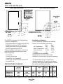
ELECTRICAL
INLET
3"
2.1"
5.7"
WATER INLET
3/8" FLARE
DRAIN
3/4" FPT
BACK VIEW: AIR COOLED
5.25"
9.5"
Note: Allow 6"
behind and 6"
above either unit
for air circulation,
utility connections,
and service.
ELECTRICAL
INLET
WATER
INLET
7.3"
5.25"
3"
3.4"
7.46"
Condenser Inlet 3/8" FPT
Condenser Drain 1/2" FPT
DRAIN
3/4" FPT
4.9"
2.9"
9.43"
BACK VIEW: WATER COOLED
SPECIFICATIONS: ICE MAKER
NM950
March, 1989
Page 2

Water Limitations:
An ice machine is a food manufacturing plant;
it takes a raw material, water, and turns it into
a food product, ice. The purity of the water is
very important in obtaining pure ice and in
maximizing product life. This is not intended
as a complete resource for water related
questions, but it does offer these general
recommendations:
1. Check with a water treatment specialist for
a water test, and recommendations regarding
filters and treatment.
2. In most cases, the water used to make ice
should be filtered or treated, depending upon
the water.
There is no one type of water filter
that will be effective in all situations.
That is
why a water test is important.
Scotsman Ice Systems are designed and
manufactured with the highest regard for
safety and performance. They meet or
exceed the standards of UL, NSF, and CSA.
Scotsman assumes no liability or responsibility
of any kind for products manufactured by
Scotsman that have been altered in any way,
including the use of any part and/or other
components not specifically approved by
Scotsman.
Scotsman reserves the right to make design
changes and/or improvements at any time.
Specifications and design are subject to
change without notice.
FOR THE INSTALLER
B590E
B590S
DIMENSIONS
H" x W" x D"
32 x 42.5 x 30.5
same
STORAGE
CAPACITY
590 lbs.
same
FINISH
Enamel
Stainless Steel
MODEL
1.25"
21.12"
Drain
3/4"
FPT
Typical Storage Bin - B590
NM950
March, 1989
Page 3

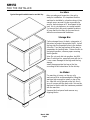
FOR THE INSTALLER
Location:
After uncrating and inspection, the unit is
ready for installation. It is important that the
machine be installed in a location where it has
enough space around it to be accessible for
service, and minimum of 6" be allowed at the
back for air circulation on air cooled models.
Try to avoid hot, dirty and crowded locations.
Be sure that the location for the machine is
within the environmental limitations.
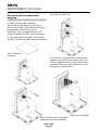
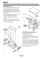
Storage Bin:
Tip the storage bin on its back, using parts of
the carton to protect the exterior finish. Install
the legs into the threaded holes in the bottom
of the bin. Turn the leg levelers all the way in
preparation for leveling later. Return the bin to
the upright position, remove paper covering
the bin gasket.
Note: Do not push bin into position, but lift it
there. Pushing a bin, especially one with ice in
it, can cause damage to the legs and the leg
mounts.
Install the appropriate bin top on the bin,
according to the instructions for the bin top.
Ice Maker:
The machine is heavy, so the use of a
mechanical lift is recommended for lifting the
machine high enough to install on top of the
bin. After the unit is placed on the bin, line it
up so it is even with the back side. Secure the
machine to the bin with the hardware provided
with the machine.
Remove the front panel and remove any
shipping blocks.
Typical Storage Bin with Extension and Bin Top
NM950
March, 1989
Page 4

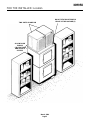
FOR THE INSTALLER: Location
TWO UNITS ON ONE BIN
ALLOW ROOM
FOR AIR
CIRCULATION
AND SERVICE
ACCESS
DO NOT STACK ANYTHING IN
FRONT OF THE MACHINE(S)
NM950
March, 1989
Page 5

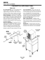
FOR THE PLUMBER
CONFORM TO ALL APPLICABLE CODES
Water Inlet
Air Cooled Models: The recommended water
supply is clean, cold water. Use 3/8" O.D.
copper tubing, connect to the 3/8" male flare
at the back of the cabinet. Install a hand valve
near the machine to control the water supply.
Water Treatment: In most areas, a water filter
of some type will be useful. In areas where the
water is highly concentrated with minerals the
water should be tested by a water treatment
specialist, and the recommendations of the
specialist regarding filtration and/or treatment
should be followed.
Water Cooled Models: A separate 3/8" O.D.
copper line is recommended, with a separate
hand valve to control it. It is connected to a
3/8" FPT condenser inlet at the back of the
cabinet. The water pressure to all lines must
always be above 20 psig, and below 120 psig.
Drains
Air Cooled Models: There is one 3/4" FPT
drain at the back of the cabinet, the drain line
is of the gravity type, and 1/4 inch per foot fall
is an acceptable pitch for the drain tubing.
There should be a vent at the highest point of
the drain line, and the ideal drain receptacle
would be a trapped and vented floor drain.
Use only 3/4" rigid tubing.
Water Cooled Models: In addition to the
above mentioned drain, a separate condenser
drain must be installed. Connect it to the 1/2"
condenser drain connection at the back of the
cabinet.
Storage Bin: A separate gravity type drain
needs to be run, similar to the air cooled drain.
Insulation of this drain line is recommended.
AIR COOLED
MODELS
HAND
VALVE
FIELD
SUPPLIED
FILTER
WATER
INLET
VENTED
DRAIN
WATER
COOLED
HAND
VALVE
CONDENSER
INLET
WATER
FILTER
CONDENSER
DRAIN
VENTED
DRAIN
NM950
March, 1989
Page 6

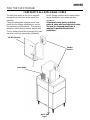
FOR THE ELECTRICIAN
CONFORM TO ALL APPLICABLE CODES
The electrical power to the unit is supplied
through the junction box at the rear of the
machine.
Check the nameplate (located on the back
panel) for the voltage requirements, and for
the minimum circuit ampacity. The machine
requires a solid chassis to earth ground wire.
The ice maker should be connected to its own
electrical circuit so it would be individually
fused. Voltage variation must remain within
design limitations, even under starting
conditions.
All external wiring must conform to
national, state, and local electrical codes.
The use of a licensed electrician is
required to perform the electrical
installation.
WATER COOLED
AIR COOLED
POWER
SUPPLY
NM950
March, 1989
Page 7

FOR THE INSTALLER
Final Check List
1. Is the ice system installed indoors in a
location where the air and water temperatures
are controlled, and where they do not exceed
the design limitations?
2. Is there an electrical service disconnect
within sight of the installed machine? Has the
voltage been checked, and compared to
nameplate requirements?
3. Have all the plumbing connections been
made and checked for leaks?
4. Has the machine and bin been leveled?
5. Is there a minimum of 6" clearance at the
back of the machine for proper service access
and air circulation?
6. Is the water pressure a minimum of 20 psig?
7. Has the machine been secured to the bin?
8. Is there clearance over the top of the
machine for service access?
9. Is there a water shut off valve installed near
the machine?
10. Have all of the shipping blocks been
removed?
NM950
March, 1989
Page 8

START UP
Pre-Start Inspection
1. Remove the front and side service panels.
2. Check that the styrofoam shipping blocks
have been removed.
3. Inspect the interior of the machine for loose
screws or wires. Check that no refrigerant
lines are rubbing each other. Check that the
fan blade turns freely (air cooled).
4. Check that the unit is installed correctly
according to the final check list (page 8).
Start Up
1. Go through the prestart inspection.
2. Open the hand valve, observe that water
enters the water reservoir, fills the tube from
the reservoir to the evaporator, and then shuts
off. Check for leaks.
3. Switch the master switch on.
The electrical start up sequence is now on
automatic.
A. There should be a short (15 second) delay
before the gearmotor starts.
B. After the gearmotor starts, the compressor
will start.
4. On air cooled models, the condenser will
begin to discharge warm air, on water cooled
models, the water regulating valve will open,
and warm water will be discharged into the
drain.
5. The unit should soon be making ice, if
desired, the low side pressure can be
checked: it should be 30 psig + or - 4 psig.
The suction line temperature at the
compressor is normally very cold, nearly to the
point of frost up to the compressor body, but
not on it.
The air cooled discharge pressure will depend
upon air and water temperatures, but should
be between 200 psig and 280 psig.
The water cooled discharge pressure should
be constant at about 220 psig.
The above numbers are for new, clean
machines, you can expect to see some values
higher, and some lower between different
units.
6. THERE ARE NO ADJUSTMENTS TO
MAKE, so replace the panels.
7. Clean and/or sanitize the storage bin
interior, wipe off the exterior with a clean,
damp cloth.
8. Give the owner/user the service manual,
instruct him/her in the operation of the unit,
and make sure they know who to call for
service.
9. Fill out the manufacturers registration card,
and mail it to the Scotsman Factory.
10. Fill out the field quality audit form, and mail
it to the Scotsman factory.
NM950
March, 1989
Page 9

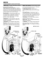
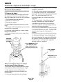
COMPONENT DESCRIPTION
Control Box: Contains the electrical controls
that operate the machine.
High Pressure Cut Out Switch: A manual
reset switch sensing the high side refrigeration
pressure. It is set to shut the machine off, and
illuminate the reset switch light if the discharge
pressure should ever exceed 450 psig.
Reset Switch: A manual reset switch, used
for restarting the ice machine should the ice
discharge chute overfill with ice; the low
pressure cut out switch open; or the high
pressure cut out switch open.
Evaporator: A vertical stainless steel tube,
refrigerated, and water filled. In it there is a
stainless steel auger.
Compressor: The refrigerant vapor pump.
Reservoir: Float operated, it maintains the
water level in the evaporator at a constant
level, it also contains the water level sensor.
Water Level Sensor: Senses if there is water
in the reservoir to make ice out of. Will shut
the machine off it there is none.
Ice Discharge Chute: Directs the ice
produced by the evaporator into the storage
bin.
Ice Level Sensor: An electronic "eye", it
senses the presence of ice in the bottom of
the ice discharge chute. Operates to turn the
ice machine on and off automatically as the
level of ice in the bin changes.
Gear Motor: An oil filled, speed reduction
gearbox, driving the auger.
Drain Tube: When uncapped and lowered,
drains the evaporator.
Condenser: Air or water cooled, where the
heat removed in ice making is discharged.
Expansion valve: The refrigerant metering
device.
AIR COOLED
CONTROL BOX
CONDENSER
EXPANSION
VALVE
RESERVOIR
ICE CHUTE
COMPRESSOR
ICE LEVEL
SENSORS
DRAIN
TUBE
WATER COOLED
CONTROL BOX
CONDENSER
EXPANSION
VALVE
RESERVOIR
ICE CHUTE
ICE LEVEL
SENSORS
HIGH
PRESSURE
CUT OUT
NM950
March, 1989
Page 10

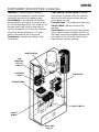
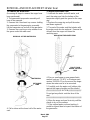
COMPONENT DESCRIPTION: Control Box
Contactor: A definite purpose contactor
connecting the compressor and the remote
condenser fan motor to the power supply.
Circuit Board: Controlling the ice machine
through sensors and relays. The sensors are
for ice level and water level. The relays are for
the gear motor (with a built in time delay to
clear the evaporator of ice when the unit turns
off) and for the liquid line valve. The reset
switch is mounted on the circuit board.
Transformer: Supplies low voltage to the
circuit board.
Low Pressure Cut Out Switch: A manual
reset control that shuts off the ice machine
when the low side pressure drops below a
preset point, 0-4 psig.
Potential Relay: The compressor start relay.
On/Off Switch: Manual control for the
machine.
Reset Switch: Part of Circuit Board, manual
reset. Lights up when unit shuts off from: ice
discharge chute being overfilled (opening the
microswitch at the top of the chute); low or
high pressure switches opening.
ON/OFF SWITCH
LOW
PRESSURE
CUT OUT
SWITCH
POTENTIAL
RELAY
TRANSFORMER
CONTACTOR
RESET SWITCH
CIRCUIT
BOARD
NM950
March, 1989
Page 11

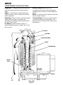
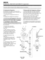
COMPONENT DESCRIPTION
Evaporator: A refrigerated vertical tube filled
with water and containing a water seal and
auger.
Auger: A solid stainless steel double spiral
auger, it pushes the ice crystals up to the top
of the evaporator.
Water Seal: A two part "face" seal, the top half
rotating with the auger, the bottom half
stationary, the sealing action being where the
two seal "faces" meet.
Ice Sweep: A plastic cap with "fingers". It
revolves with the auger to "sweep" the ice into
the ice chute.
Breaker (Divider): Where the ice is
compressed and much of the extra water is
squeezed out of it before it is discharged into
the bin.
Motor: A permanent split capacitor motor that
drives the gear reducer.
Thrust Bearing: As the ice is pushed up the
evaporator, the auger is thrust down, and
pressure from the auger thrust is taken up by
this bearing.
WATER
SEAL
ICE SWEEP
BEARING
BREAKER/DIVIDER
AUGER
EVAPORATOR
MOTOR
NM950
March, 1989
Page 12

ELECTRICAL SEQUENCE
Refer the wiring diagram as needed.
If the machine is switched off at the master
switch, but is otherwise ready to go, switching
the master switch to on does the following:
••The bin empty light on the circuit board
goes on
••
There is a 15 second delay
••If there is enough water in the reservoir, the
circuit board will allow the machine to start
up.
Start up consists of:
••The compressor relay and auger motor
relay become energized, connecting power
to the windings of the auger motor.
••The auger motor starts, and the centrifugal
switch closes, connecting power to the
compressor contactor coil.
••The contactor is energized, connecting
power to the compressor, and the
compressor starts.
••As ice goes past the ice level sensors, the
bin empty light will stay on, and the
machine will continue to run, unless the ice
stays between the sensors for more than
15 seconds (bin full). At that point, the bin
empty light goes out, and the machine
shuts down.
Shut Down consists of:
••
The compressor relay opens.
••The compressor contactor opens
••The compressor stops
••The auger motor is run by the circuit board
for 2.5 more minutes, clearing out ice in the
evaporator, and then
••The auger motor relay opens, and the
auger motor stops.
If the ice level sensor is clear (bin empty) for
more than 15 seconds, the machine will start
up again.
Another purpose of the circuit board is to turn
the machine off if there is not enough water in
the machine.
••When the water level in the reservoir falls
below the water level sensor, the machine
will "shut down"
••When the water refills the reservoir, the
machine will start up again.
Separate from the circuit board:
••If the high pressure control (cut out switch)
opens, the machine will stop immediately
(through the relays on the circuit board) and
cause the reset switch on the circuit board
to light up. It must be manually reset at the
control and at the reset switch on the circuit
board.
••If the low pressure control (cut out switch)
opens, the machine will stop immediately
(through the relays on the circuit board) and
cause the reset switch on the circuit board
to light up. It must be manually reset at the
control and at the reset switch on the circuit
board.
••If the spout switch opens, the machine will
stop immediately (through the relays on the
circuit board) and cause the reset switch on
the circuit board to light up. After it recloses
the reset switch on the circuit board must
be manually reset.
••The master switch is the manual control for
the complete machine, but it is not a
service disconnect.
NM950
March, 1989
Page 13

OPERATION: Water
Water enters the machine through the 3/8"
male flare at the rear of the cabinet, goes to a
strainer and then to the water reservoir which
it enters through the float valve. The water
then goes out the bottom of the reservoir tank
to the bottom of the evaporator.
Reservoir overflow or evaporator
condensation is routed to the drain. Water
cooled models have a separate water circuit
for the cooling water: it enters the fitting at the
rear, goes to the water regulating valve, then
to the water cooled condenser and down the
drain.
ADJUSTMENT OF WATER LEVEL
SPOUT
SWITCH
EVAPORATOR
DRAIN
WATER LEVEL
EVAPORATOR
ICE
CHUTE
DRAIN
STRAINER
WATER SCHEMATIC
RESERVOIR
NM950
March, 1989
Page 14

OPERATION: Refrigeration
Beginning at the compressor, the refrigerant
502 is compressed into a high temperature
gas. The discharge line directs this gas to the
condenser. At the condenser (air or water
cooled) the gas is cooled by either air or water
and it then condenses into a liquid. This high
pressure liquid then goes through the liquid
line to the expansion valve. The thermostatic
expansion valve meters liquid refrigerant into
the evaporator, the volume of liquid refrigerant
depending upon the temperature of the
evaporator; warmer evaporators get more
refrigerant and colder evaporators get less. At
the evaporator, the refrigerant enters an area
of relatively low pressure, where it can easily
"boil off" or evaporate. As it evaporates, it
absorbs heat from the evaporator and
whatever is in contact with it (such as the
water inside it). After the evaporator, the
refrigerant, now a low pressure vapor, goes
through the suction line back to compressor,
where the cycle is repeated.
CONDENSER
FAN
MOTOR
LIQUID
LINE
THERMOSTATIC
EXPANSION
VALVE
SUCTION LINE
EVAPORATOR
GEAR
MOTOR
COMPRESSOR
HIGH PRESSURE
CUT OUT SWITCH
DISCHARGE
LINE
Refrigeration Schematic
NM950
March, 1989
Page 15

MAINTENANCE AND CLEANING
//////////////////////////////////////////////////////////////////////////////////////////////////////////////////////////////////////////////////////////
A Scotsman Ice System represents a sizable investment of time and money in any company’s
business. In order to receive the best return for that investment, it MUST receive periodic
maintenance.
It is the USER’S RESPONSIBILITY to see that the unit is properly maintained. It is always
preferable, and less costly in the long run, to avoid possible down time by keeping it clean;
adjusting it as needed; and by replacing worn parts before they can cause failure. The following
is a list of recommended maintenance that will help keep the machine running with a minimum of
problems.
Maintenance and Cleaning should be scheduled at a minimum of twice per year.
///////////////////////////////////////////////////////////////////////////////////////////////////////////////////////////////////////////////////////////
/////////////////////////////WARNING////////////////////////////
Electrical power will be ON when doing in
place cleaning. Switch it OFF before
completing the cleaning procedures.
///////////////////////////////////////////////////////////////////////////
ICEMAKING SYSTEM: In place cleaning
1. Check and clean any water treatment
devices, if any are installed.
2. Remove screws, and the front and top
panels.
3. Move the ON-OFF switch to OFF.
4. Remove all the ice from the storage bin.
5. Remove the cover to the water reservoir
and block the float up.
6. Drain the water reservoir and freezer
assembly using the drain tube attached to the
freezer water inlet. Return the drain tube to its
normal upright position and replace the end
cap.
///////////////////////////WARNING//////////////////////////////
Scotsman Ice Machine Cleaner contains
Phosphoric and Hydroxyacetic acids.
These compounds are corrosive and may
cause burns. If swallowed, DO NOT induce
vomiting. Give large amounts of water or
milk. Call Physician immediately. In case
of external contact, flush with water. KEEP
OUT OF THE REACH OF CHILDREN.
//////////////////////////////////////////////////////////////////////////
7. Prepare the cleaning solution: Mix eight
ounces of Scotsman Ice Machine Cleaner with
three quarts of hot water. The water should be
between 90-115 degrees F.
8. Slowly pour the cleaning solution into the
water reservoir until it is full. Wait 15 minutes,
then switch the master switch to ON.
9. As the ice maker begins to use water from
the reservoir, continue to add more cleaning
solution to maintain a full reservoir.
10. After all of the cleaning solution has been
added to the reservoir, and the reservoir is
nearly empty, switch the master switch to OFF.
11. After draining the reservoir, as in step 6,
wash and rinse the water reservoir.
12. Remove the block from the float in the
water reservoir.
13. Switch the master switch to ON
14. Continue ice making for at least 15
minutes, to flush out any cleaning solution.
Check ice for acid taste - continue icemaking
until ice tastes sweet.
//////////////////////////////WARNING///////////////////////////
DO NOT USE any ice produced from the
cleaning solution.
Be sure no ice remains in the bin.
///////////////////////////////////////////////////////////////////////////
15. Remove all ice from the storage bin.
16. Add warm water to the ice storage bin and
thoroughly wash and rinse all surfaces within
the bin.
17. Sanitize the bin interior with an approved
sanitizer using the directions for that sanitizer.
18. Replace the panels.
NM950
March, 1989
Page 16

///////////////////////////WARNING/////////////////////////////
Disconnect electrical power before
beginning.
//////////////////////////////////////////////////////////////////////////
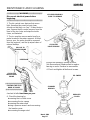
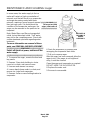
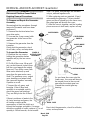
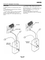
1. The bin control uses devices that sense
light, therefore they must be kept clean
enough so that they can “see”. At least twice a
year, remove the bin control sensors from the
base of the ice chute, and wipe the inside
clean, as illustrated.
2. The ice machine senses water level by a
probe located in the water reservoir. At least
twice a year, the probe should be removed
from the reservoir, and the tip wiped clean of
mineral buildup.
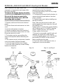
3. The bearing in the breaker should also be
checked at least two times per year.
A. Check the bearing by:
••removing the ice chute cover
••
unscrewing the ice sweep
••removing the water shed
••using a spanner wrench and unscrewing
the breaker cover.
••unscrewing the auger stud
Inspect the assembly, looking for wear.
See Removal and Replacement to replace
bearing or seals. Reverse to reassemble.
4. Check and tighten all bolts and screws.
CLEAN THE
WATER LEVEL
PROBE
PULL UP TO
REMOVE PROBE
RESERVOIR
///////////////////////////////////////////
CAUTION: THE TIP IS
MADE OF GLASS
//////////////////////////////////////////
ICE LEVEL SENSORS:
SLIDE TO REMOVE
CLEAN THE
LIGHT SENSORS
MAINTENANCE AND CLEANING
ICE SWEEP
SPANNER
WRENCH
BREAKER
COVER
NM950
March, 1989
Page 17

///////////////////////////WARNING/////////////////////////////
Disconnect electrical power before
beginning.
//////////////////////////////////////////////////////////////////////////
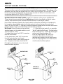
5. Clean the air cooled condenser.
The air flow on this model is from front to
back, so the inside of the machine will have to
be available to clean the air cooled
condenser. Use a vacuum cleaner or coil
cleaner if needed. Do NOT use a wire brush.
A. Disconnect electrical power, and remove
the filter. The filter may be cleaned or replaced.
B. Clean the condenser: the condenser may
appear to be clean on the surface, but it can
still be clogged internally. Check with a flash
light from the front to see if light can be seen
though the condenser fins.
Reverse to reassemble.
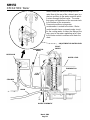
MAINTENANCE: Air Cooled
Step 1: Remove
top panel.
Step 3. Pull fan motor assembly off of locating
pins and out of the unit.
Step 2. Remove two screws and
unplug the fan motor assembly.
NM950
March, 1989
Page 18

In some areas, the water supply to the ice
maker will contain a high concentration of
minerals, and that will result in an evaporator
and auger becoming coated with these
minerals, requiring a more frequent removal
than twice per year. If in doubt about the
condition of the evaporator and auger, the
auger can be removed so the parts can be
inspected.
Note: Water filters can filter out suspended
solids, but not dissolved solids. “Soft” water
may not be the complete answer. Check with
a water treatment specialist regarding water
treatment.
For more information on removal of these
parts, see REMOVAL AND REPLACEMENT.
//////////////////////////////WARNING////////////////////////////
Switch off electrical power, and turn off the
water supply.
//////////////////////////////////////////////////////////////////////////
1. To remove the auger, remove the front and
top panels.
2. Remove 3 hex studs holding ice chute
cover to ice chute, and remove cover.
3. Unscrew and remove ice sweep.
4. Loosen band clamp under ice chute, and
remove ice chute from evaporator.
5. Remove 4 allen screws holding breaker to
evaporator.
6. Drain the evaporator by lowering and
uncapping the evaporator drain hose.
7. Pull up to remove auger.
After the auger has been removed, allow the
auger to dry: if the auger is not bright and
shiny, it must be cleaned.
Clean the auger and evaporator as required.
DO NOT HONE THE EVAPORATOR.
8. Replace the water seal.
9. Reverse to reassemble.
/////////////WARNING///////////////
The auger has sharp
edges, handle with care.
////////////////////////////////////////////
MAINTENANCE AND CLEANING: Auger
ALLEN
SCREWS
BREAKER &
BEARING &
AUGER
ASSEMBLY
NM950
March, 1989
Page 19

SERVICE DIAGNOSIS: Condition - No Ice Being Produced
STATUS:
NOTHING OPERATES
A. Check: Voltage to the unit, restore it if there is none. Compare to the nameplate.
B. Check: The master switch, switch ON if off.
C. Check: The 3 reset switches, (circuit board, high and low pressure): depress and release
each switch. If the still does not start, check: the spout switch; the high and the low side
pressures.
D. Check the low pressure cut out, if closed, go to E; if it is open, it could be due to:
••
Low refrigerant charge
••The auger not turning
••
Restricted system
••TXV not opening
1. Check the low side pressure, the low pressure cut out opens at pressure below 4 psig.
If open, reset and:
a. Check if the auger is turning, if it is not, remove the gearbox and:
Check for internal damage, repair and replace in the machine.
b. Check for low charge, add some refrigerant, if the unit will operate,(normal
low side pressure being about 30 psig) stop and look for a leak, repair, replace the
drier, evacuate, and weigh in the nameplate charge. If, with added charge, the unit
does not operate:
Check for a restricted system, replace the drier, evacuate, and weigh in a
nameplate charge.
Check for a Thermostatic Expansion Valve that does not open, if defective,
replace it. Replace the drier, evacuate, and weigh in the nameplate charge.
E. Check the high pressure cut out, if closed go to F, if open check
1.The pressure control opens at 450 psig. Check the high side pressure, reset the control,
and observe: on water cooled, that water soon begins to flow from the condenser drain;
or, on air cooled, that the fan is forcing air through the condenser. If the unit trips out on
pressures below 450 psig, replace the control. If the pressures rise above the trip out
point, and the unit shuts down:
a. Check for adequate water flow on water cooled, if adequate, clean the interior
of the condenser. If the pressures are still too high replace the water regulating valve.
b. Check for adequate air flow on air cooled. Clean the condenser and (if used) the
filter. If the air flow is poor because of the installation, advise the user that the unit
should be moved, or the air around it kept cooler.
Check the fan motor for tight bearings and proper rotation.
Check that the fan blades are clean, and the fan secure to the fan motor shaft.
F. Check the spout switch. It opens from excess pressure of ice inside the ice chute: this should
only happen when the machine does not shut off when the ice storage bin is full. This switch will
reset when the ice melts, but the machine will not resart until the reset switch on the circuit board
is pressed.
G. Check the water level in the reservoir. The machine will not run if there is not enough water in
the reservoir.
1. Restore/adjust water level. See the next step.
NM950
March, 1989
Page 20
Page is loading ...
Page is loading ...
Page is loading ...
Page is loading ...
Page is loading ...
Page is loading ...
Page is loading ...
Page is loading ...
Page is loading ...
Page is loading ...
Page is loading ...
-
 1
1
-
 2
2
-
 3
3
-
 4
4
-
 5
5
-
 6
6
-
 7
7
-
 8
8
-
 9
9
-
 10
10
-
 11
11
-
 12
12
-
 13
13
-
 14
14
-
 15
15
-
 16
16
-
 17
17
-
 18
18
-
 19
19
-
 20
20
-
 21
21
-
 22
22
-
 23
23
-
 24
24
-
 25
25
-
 26
26
-
 27
27
-
 28
28
-
 29
29
-
 30
30
-
 31
31