DO GUIDE
DOC. 8345A (2052212) 07.18
Specications subject to change without notice.
NOTES:
• The POE IN port does not provide a network connection. The port
is only used to enable PoDM or PoDM+.
• The internal power supply of a DigitalMedia switcher does not
power DM 8G+ endpoints.
• When PoDM or PoDM+ is used to power a DM 8G+ endpoint,
connection of the endpoint to the included power pack is
not required.
• Cabling that connects to a PoDM or PoE PSE port is designed for
intrabuilding use only.
DO Route Inputs
Route inputs to one or more of the available outputs by using the front panel
controls or the web interface.
Route Inputs Using the Front Panel Controls
To route inputs using the front panel controls:
1. Press the ROUTE button. The AUDIO, VIDEO, and USB LEDs
light, indicating the signal types that are to be routed.
(Pressing the AUDIO, VIDEO, and USB buttons selects or
deselects the corresponding signal type.)
2. Press the appropriate IN button that corresponds to the input to
be routed. The LED of the selected input lights. In addition, the
LEDs of the outputs to which the input is currently routed
also light.
3. Press the appropriate OUT buttons that correspond to the desired
outputs. The LEDs of the selected outputs ash to indicate that
the input is not yet routed.
4. Press the ENTER button to route the input. The LEDs of the
selected outputs light steadily. The display shows the input
number and the outputs to which the input is routed.
To disconnect an input from an output:
1. Press the ROUTE button.
2. Press the desired OUT button. The display shows IN None.
3. Press the ENTER button. The output is disconnected from
the input.
Route Inputs Using the Web Interface
To route inputs using the web interface:
1. Find the IP address of the device by using the Device Discovery
Tool in the Crestron Toolbox™ software.
2. Open a web browser and go to the IP address.
3. On the home page:
a. Click the input to be routed.
b. Click the desired outputs.
c. Click Take.
DO Congure the Device
Congure input, output, and network settings by using the front panel
controls and Installer Tools or by using the web interface.
Conguration of network settings includes:
• IP address
• Subnet mask
• Default router
• DHCP
• Hostname
• Control system IP address
In addition, be aware of Private Network Mode (PNM). Using PNM, a DM
®
system uses only one IP address in the public network:
• PNM is enabled by default and cannot be disabled.
• In a DM system containing a single DM switcher, the DM
switcher is the only DM device that uses an IP address in the
public network. When DHCP is enabled, the IP address is set
dynamically. When DHCP is disabled, the IP address must be
set manually.
• All DMC I/O cards and DM endpoints (transmitters and receivers)
connected to the DM switcher are hidden from the public network
and cannot be reached directly. All communication is managed
through the DM switcher. PNM creates a completely private IP
network for all cards and endpoints.
NOTE: When a DM endpoint connects to a DM switcher, the
convenience Ethernet port of the endpoint must not be connected
to the LAN. A DM endpoint receives a network connection via the
DM switcher. The convenience Ethernet port of a DM endpoint is
available for connection to a network device such as a PC,
Blu-ray™ player, or TV.
• When multiple DM switchers are cascaded:
○ Each DM switcher must connect directly to the LAN.
A DM switcher cannot connect to the LAN through another
DM switcher.
○ Each DM switcher must be assigned a unique system ID.
PNM uses the system ID of each switcher to determine the
internal IP address used by each device in the DM system.
To assign a unique system ID, refer to the following section.
DO Assign a Unique System ID
When multiple DM switchers are cascaded, assign a unique system ID to
each switcher by using the front panel controls and Installer Tools or by
using the web interface. The system ID ranges from 1 to 64. The default
system ID is 1.
NOTE: It is recommended that a number ranging from 2 to 64 be used.
A system ID other than the default setting of 1 prevents potential conicts
when bringing additional switchers online.
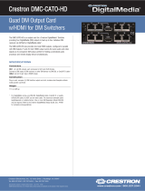
Assign a Unique System ID Using the Front Panel Controls
To assign a unique system ID using the front panel controls:
1. In Installer Tools, select Network Setup.
The Network Setup conguration screen appears.
2. Select System ID.
The Edit System ID conguration screen appears.
3. Select a unique system ID for the DM switcher. The recommended
setting ranges from 2 to 64.
4. Press the MENU button to exit Installer Tools.
Assign a Unique System ID Using the Web Interface
To assign a unique system ID using the web interface:
1. Find the IP address of the device by using the Device Discovery
Tool in the Crestron Toolbox software.
2. Open a web browser and go to the IP address.
3. On the Ethernet page, select a unique system ID for the
DM switcher. The recommended setting ranges from 2 to 64.
DO Connect to the Crestron XiO Cloud Service
The Crestron XiO Cloud
®
service allows supported Crestron devices across
an enterprise to be managed and congured from one central and secure
location in the cloud. Supported devices are precongured to connect to
the service. Use of the service requires a registered Crestron XiO Cloud
account.
To connect the device to the Crestron XiO Cloud service:
1. Record the MAC1 address and the serial number that are labeled
on the shipping box of the device. The MAC1 address, which is
the MAC address of the LAN port on the DMC-CPU3 card, is also
labeled on the faceplate of the card. The serial number is also
labeled on the printed circuit board (PCB) of the DMC-CPU3 card.
The MAC1 address and the serial number are required in order to
add the device to the Crestron XiO Cloud environment.
2. Do either of the following:
• If you have a Crestron XiO Cloud account, go to
https://portal.crestron.io to access the Crestron XiO
Cloud service.
• If you do not have a Crestron XiO Cloud account, go to
www.crestron.com/xiocloud to register for an account.
For detailed information about using the Crestron XiO Cloud service, refer to
the Crestron XiO Cloud Service User Guide (Doc. 8214) at
www.crestron.com/manuals.
As of the date of manufacture, the product has been tested and found to comply with
specications for CE marking.
This product is Listed to applicable UL
®
Standards and requirements tested by
Underwriters Laboratories Inc.
Ce produit est homologué selon les normes et les exigences UL applicables par
Underwriters Laboratories Inc.
Federal Communications Commission (FCC) Compliance Statement
This device complies with part 15 of the FCC Rules. Operation is subject to the following two
conditions:
(1) This device may not cause harmful interference, and (2) this device must accept any interference
received, including interference that may cause undesired operation.
CAUTION: Changes or modications not expressly approved by the manufacturer responsible for
compliance could void the user’s authority to operate the equipment.
NOTE: This equipment has been tested and found to comply with the limits for a Class B digital
device, pursuant to part 15 of the FCC Rules. These limits are designed to provide reasonable
protection against harmful interference in a residential installation. This equipment generates,
uses and can radiate radio frequency energy and, if not installed and used in accordance with
the instructions, may cause harmful interference to radio communications. However, there is no
guarantee that interference will not occur in a particular installation.
If this equipment does cause harmful interference to radio or television reception, which can
be determined by turning the equipment off and on, the user is encouraged to try to correct the
interference by one or more of the following measures:
• Reorient or relocate the receiving antenna.
• Increase the separation between the equipment and receiver.
• Connect the equipment into an outlet on a circuit different from that to which the receiver is
connected.
• Consult the dealer or an experienced radio/TV technician for help.
Industry Canada (IC) Compliance Statement
CAN ICES-3(B)/NMB-3(B)
The DMC Fiber Series are class 1 laser products. They comply with safety
regulations of IEC-60825-1, FDA 21 CFR 1040 11 and FDA 21 CFR 1040 10.
WARNING: Visible and invisible laser radiation when open. Avoid direct exposure to beam.
NOTE: Plug the included dust cap into the optical transceiver when the ber optic cable is
unplugged.
Rack Mounting Safety Precautions
• Elevated Operating Ambient Temperature: If installed in a closed or multi-unit rack assembly, the operating
ambient temperature of the rack environment may be greater than room ambient temperature. Therefore,
consideration should be given to installing the equipment in an environment compatible with the maximum
ambient temperature (Tma) specied by the manufacturer.
• Reduced Airow: Installation of the equipment in a rack should be such that the amount of airow required for
safe operation of the equipment is not compromised.
• Mechanical Loading: Mounting of the equipment in the rack should be such that a hazardous condition is not
achieved due to uneven mechanical loading.
• Circuit Overloading: Consideration should be given to the connection of the equipment to the supply circuit and
the effect that overloading of the circuits might have on overcurrent protection and supply wiring. Appropriate
consideration of equipment nameplate ratings should be used when addressing this concern.
• Reliable Earthing: Reliable earthing of rack-mounted equipment should be maintained. Particular attention should
be given to supply connections other than direct connections to the branch circuit (e.g., use of power strips).
Electrical Connection
“This product must be connected to an earthed mains socket-outlet.”
• Finland: “Laite on liitettävä suojamaadoituskoskettimilla varustettuun pistorasiaan.”
• Norway: “Apparatet må tilkoples jordet stikkontakt.”
• Sweden: “Apparaten skall anslutas till jordat uttag.”
The specic patents that cover Crestron products are listed at http://www.crestron.com/legal/patents.
The product warranty can be found at www.crestron.com/warranty.
Certain Crestron products contain open source software. For specic information, please visit www.crestron.com/opensource.
Manufactured under license under U.S. Patent Nos.: 5,956,674; 5,974,380; 6,226,616; 6,487,535; 7,212,872; 7,333,929; 7,392,195; 7,272,567
& other U.S. and worldwide patents issued & pending. DTS-HD, the Symbol, & DTS-HD and the Symbol together are registered trademarks of DTS,
Inc. Product includes software. © DTS, Inc. All Rights Reserved.
Manufactured under license from Dolby Laboratories. Dolby and the double-D symbol are trademarks of Dolby Laboratories.
Crestron, the Crestron logo, Crestron Toolbox, Crestron XiO Cloud, DigitalMedia, DM, and DM 8G+ are either trademarks or registered trademarks
of Crestron Electronics, Inc., in the United States and/or other countries. Blu-ray is either a trademark or registered trademark of the Blu-ray Disc
Association in the United States and/or other countries. HDBaseT and the HDBaseT Alliance logo are either trademarks or registered trademarks
of the HDBaseT Alliance in the United States and/or other countries. HDMI and the HDMI logo are either trademarks or registered trademarks of
HDMI Licensing LLC in the United States and/or other countries. UL and the UL logo are either trademarks or registered trademarks of Underwriters
Laboratories, Inc. in the United States and/or other countries. Other trademarks, registered trademarks, and trade names may be used in this
document to refer to either the entities claiming the marks and names or their products. Crestron disclaims any proprietary interest in the marks
and names of others. Crestron is not responsible for errors in typography or photography.
©2018 Crestron Electronics, Inc.
DO Learn More
Visit the website for additional information and the latest rmware updates.
Crestron Electronics
15 Volvo Drive, Rockleigh, NJ 07647
888.CRESTRON | www.crestron.com
Edit System ID
1
Network Setup
Domain Name
MAC Address
System ID: 1
Network Setup
Ethernet Link
IP Address
Subnet Mask
Installer Tools
Inputs
Outputs
Network Setup