Instruction
Manual
Direct Measuring
Cavity Pressure
Sensor with ø1,2 mm
Machinable Sensor
Front
Type 6184AA...
6184A_002-419e-05.08

Instruction
Manual
Direct Measuring
Cavity Pressure
Sensor with ø1,2 mm
Machinable Sensor
Front
Type 6184AA...
6184A_002-419e-05.08


Foreword
6184A_002-419e-05.08 Page 1
Foreword
We thank you for choosing a Kistler quality product
distinguished by technical innovation, precision and long
life.
Information in this document is subject to change without
notice. Kistler reserves the right to change or improve its
products and make changes in the content without
obligation to notify any person or organization of such
changes or improvements.
© 2008 Kistler Group. All rights reserved. Except as
expressly provided herein, no part of this manual may be
reproduced for any purpose without the express prior
written consent of Kistler Group.
Kistler Group
Eulachstrasse 22
8408 Winterthur
Switzerland
Tel. +41 52 224 11 11
Fax +41 52 224 14 14
www.kistler.com

Content
Page 2 6184A_002-419e-05.08
Content
1. General .......................................................................................................................................... 3
2. Important Areas of Hole................................................................................................................. 4
3. Holes for Sensors ........................................................................................................................... 5
3.1 Unmachined Sensors ............................................................................................................ 5
3.1.1 Sensor with Mounting Nut Type 6465 .................................................................... 6
3.1.2 Sensor with Thrust Washer Type 6470 .................................................................... 6
3.2 Hole for Cavity-Matched Sensor .......................................................................................... 7
3.2.1 Matching Sensor Front to Cavity Profile .................................................................. 7
4. Cable Installation and Connectors ................................................................................................. 8
4.1 Single-Wire Cables ............................................................................................................... 8
4.1.1 Single-Wire Clamping Connector Type 1839 and Mounting Plate .......................... 9
4.1.2 Multi-Channel Single-Wire Connector Types 1708A... and 1710A.......................... 9
4.1.2.1 Recess for 4-Channel Connector Type 1708A.......................................... 9
4.1.2.2 Recess for 8-Channel Connector Type 1710A........................................ 10
5. Sensor Installation ....................................................................................................................... 11
5.1 Sensor Installation with Mounting Nut Type 6465 ............................................................ 11
5.2 Mounting Sensor with Thrust Washer Type 6470 .............................................................. 12
5.2.1 Machining Thrust Washer ..................................................................................... 12
6. Cable and Connector ................................................................................................................... 13
6.1 Single-Wire Technique ....................................................................................................... 13
6.1.1 Cut and Grip Technique ........................................................................................ 14
6.1.2 Connector Installation ........................................................................................... 14
6.1.2.1 Installing Connector Type 1839 ............................................................. 14
6.1.2.2 Installation for Multi-Channel Connector Types 1708A… and 1710A… 15
7. Identification Plate....................................................................................................................... 16
8. Functional Test............................................................................................................................. 17
8.1 Insulation Testing ............................................................................................................... 17
8.2 Checking Sensor Operation................................................................................................ 18
9. Servicing and Repair .................................................................................................................... 19
9.1 Insulation Testing ............................................................................................................... 19
9.2 Checking Sensor Operation................................................................................................ 20
9.3 Removing Sensor ............................................................................................................... 20
9.4 Single-Wire Repairs ............................................................................................................ 21
9.5 Repairs at Kistler................................................................................................................. 21
9.6 Disposal of Electronic Equipment........................................................................................ 21
10. Measuring Chains........................................................................................................................ 22
10.1 Machine-Integrated Mold-Cavity Pressure Monitoring ...................................................... 22
10.2 Mold Cavity Pressure Monitoring with External Kistler Instruments.................................... 23

General
6184A_002-419e-05.08 Page 3
1. General
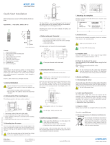
ø3,5 mm sensor diameter must not be machined
Front of sensor must be clean and free from scoring
Only use recommended mounting tool
Do not pull sensor out of the hole by the cable
Fig.1: Cavity pressure sensor Type 6184AA…
Fig.2: Dimensions of Type 6184AA...

Important Areas of Hole
Page 4 6184A_002-419e-05.08
2. Important Areas of Hole
The measuring hole can affect the operation and service
life of the sensor. As the loads on the sensor may include
shear forces, inaccurate holes can lead to measuring errors
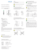
Fig.3: Important features of measuring hole
The following criteria must be met to achieve these:
1. Sensor contact surface must be flat and perpendicular
2. Hole with H7 tolerance to center sensor
3. Chamfer to assist installation
4. Sharp edges reduce witness mark on part

Holes for Sensors
6184A_002-419e-05.08 Page 5
3. Holes for Sensors
The sensor is mounted in the measuring hole with its front
flush with the wall of the cavity. The pressure in the cavity is
transferred via the front of the sensor directly to the
piezoelectric measuring element which generates a
proportional charge. In the amplifier the measurement
signals are converted into a voltage and amplified into a
standardized voltage signal used to record the pressure
curve.
The front of sensors that have not been chrome plated can
be machined to ensure it fits flush into the wall of the
cavity.
Clean hole and thread of metal particles and debris
Use tool Type 1365 to check the size and centering of
the hole. Minor corrections can be done by lapping
3.1 Unmachined Sensors
For pressure measurements in flat parts or on those parts
with a flat cavity wall the sensor is mounted in a hole at
right angles to the wall of the cavity without machining.
The front of the mounted sensor must be flush with the
wall of the cavity. To achieve this the hole is matched to
the size of the sensor dimension of the front measuring
body.
A spacer sleeve and mounting nut are normally used to
secure this sensor in a cavity insert. The low overall height
and lateral cable outlet also allow side mounting in the
cavity.
With thin mounting plates, installation with a spacer sleeve
and thrust washer is practical.
The spacer sleeve Type 6466 used for both methods
ensures correct mounting with sufficient play to prevent
preloading of the sensor. This sleeve must therefore always
be used.

Holes for Sensors
Page 6 6184A_002-419e-05.08
3.1.1 Sensor with Mounting Nut Type 6465
Erode, mill or grind H7 hole in hardened tool steel. Ensure
proper centering and alignment. Clean thread free of
debris and metal particles.
Fig.4: Sensor hole for installation with spacer sleeve
and mounting nut; spacer sleeve; mounting nut
Always use spacer sleeve Type 6466
3.1.2 Sensor with Thrust Washer Type 6470
Erode, mill or grind H7 hole in hardened tool steel. Ensure
proper centering and alignment
Fig.5: Sensor hole for installation with sleeve and
thrust washer; spacer sleeve; thrust washer

Holes for Sensors
6184A_002-419e-05.08 Page 7
3.2 Hole for Cavity-Matched Sensor
The sensor can be adapted to match the profile of an
oblique, or one with a slated surface or freeform cavity
wall.
The front of the sensor can be re-machined within certain
limits, either directly or after mounting.
3.2.1 Matching Sensor Front to Cavity Profile
The front of the sensor can be machined with a radius or
slanted surface, also when mounted in the mold. However,
if the cavity wall is eroded with a mounted sensor, it must
be ensured that no liquid enters the connector, for example
by sealing the rear sensor body with silicone sealant. The
end of the cable should always be secured outside the
erosion bath.
After the front of the sensor has been machined, the
sensor is removed (a magnet works well) and dried. Clean
and dry the hole.
Fig. 6: Allowable front radius and angle
Pull sensor out of the hole with magnet
Use cleaning spray Type 1003

Cable Installation and Connectors
Page 8 6184A_002-419e-05.08
4. Cable Installation and Connectors
The cables for piezoelectric sensors must be well insulated.
Cables and connectors must be installed with good
protection to prevent cable damage during installation and
in operation. Moisture and dirt in the area of the connector
must be prevented in order to ensure optimum function.
Recommendations for cable installation:
Install cables with sufficient slack to ensure they are not
under strain
Secure cables in the channel with putty/mastic to simplify
mold mounting
Do not install cables around hot runner cartridges or in
hot runner holes
Use sufficient radii at transitions and corners in the cable
channel and holes to prevent cable damage
Cover open channels
4.1 Single-Wire Cables
With the single-wire method, electrical shielding is pro-
vided by the injection mold. Thus the cable must be
integrated in the mold body and never be installed outside
the mold. In the case of an open channel, a cover plate
must be provided. All contact surfaces and threads for the
connectors must in addition be electrically conductive,
clean and free of grease.
The single-wire cable must on no account be installed toge-
ther with other electrical cables such as the power supply for
hot runner systems in the cable hole.
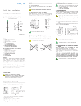
Electrical shielding is mandatory: install single-wire
cable completely in the mold and cover open channels
To prevent interference signals, never install single-
wire cables together with power cables
To ensure effective insulation, contact surfaces and
threads must be clean and dry
Single-wire cable can be run through a drilled hole

Cable Installation and Connectors
6184A_002-419e-05.08 Page 9
4.1.1 Single-Wire Clamping Connector Type 1839 and Mounting Plate
Mill a recess for the mounting plate. Contact surfaces and
threads must be clean and free of grease. Provide radii at
transitions and corners in the cable channel or hole, so as to
prevent cable damage during assembly and in operation.
Example shows installation in a hole.
Fig. 7: Hole and recess for connector Type 1839
Example shows installation in a channel.
Fig. 8: Channel and recess for connector Type 1839
4.1.2 Multi-Channel Single-Wire Connector Types 1708A... and 1710A...
Mill a recess for the multi-channel connector. Contact
surfaces and threads must be clean and free from grease.
Provide radii at transitions and corners in the cable channel or
hole, so as to prevent cable damage during assembly and
in operation.
4.1.2.1 Recess for 4-Channel Connector Type 1708A...
Wherever possible, position the cable channel or cable hole
in the middle of the recess to simplify connection of the
sensors. When space is limited, the cable entry can be
located as required, in which a side entry at the level of the
base may be used.

Cable Installation and Connectors
Page 10 6184A_002-419e-05.08
Fig. 9: Recess for multi-channel connector Type
1708A…
4.1.2.2 Recess for 8-Channel Connector Type 1710A...
Wherever possible, position the cable channel or cable hole
in the middle of the recess to simplify connection of the
sensors. When space is limited, the cable entry can be
located as required, in which a side entry at the level of the
base may be used.
Fig. 10: Recess for multi-channel connector Type
1710A…
Observe radii
Cover open channel with sheet metal plate

Sensor Installation
6184A_002-419e-05.08 Page 11
5. Sensor Installation
The sensor is mounted with a spacer sleeve first, then the
cable and finally the connector fitted. It is particularly
important to carry out the steps in this order when
mounting single-wire sensors, whose cable is shortened to
the required length in the mold.
To ensure sufficient play the spacer sleeve must always be
used.
All sensor holes and threads must be clean
Radii in the channel and transitions prevent cable
damage
5.1 Sensor Installation with Mounting Nut Type 6465
The sensor is placed into the spacer sleeve with the tip and
can be pushed into the hole with a magnet or tweezers.
Screw mounting nut in with tubular socket wrench Type
1363. Tighten mounting nut carefully to avoid overloading.
Fig.11: Installation with nut
Do not machine spacer sleeve Type 6466
Do not preload sensor or spacer sleeve
Secure mounting nut with tubular socket wrench
Type 1363

Sensor Installation
Page 12 6184A_002-419e-05.08
5.2 Mounting Sensor with Thrust Washer Type 6470
The sensor is placed into the spacer sleeve with the tip and
can be pushed into the hole with tweezers.
5.2.1 Machining Thrust Washer
Whenever possible adapt mold insert or plate to match the
dimension shown on the drawing. If this is not possible,
mount sensor and spacer sleeve and determine dimension
needed to achieve height dimension. Lap thrust washer
until square and flat, then deburr and fit.
Fig.12: Mounting with thrust washer Type 6470
Do not machine spacer sleeve Type 6466
Do not preload sensor
For multi-cavity molds the thrust washers must be
numbered and matched to the individual sensors

Cable and Connector
6184A_002-419e-05.08 Page 13
6. Cable and Connector
The most frequent sensor failures are caused by damage to
the cable during installation. It is essential to allow suffi-
cient slack when installing the cable and the connector.
Edges and transitions should thereby be provided with radii
and a sufficient length of cable installed to ensure that it is
not under strain.
To prevent any possible damage to the cable during instal-
lation in the mold, it is advisable to cover open channels or
to secure the cable with mastic.
Good shielding is important for low-noise signal trans-
mission. Covers must be placed over open connectors.
Remove sharp edges in the cable hole and the chan-
nel; provide radii
Secure the cover on the mold and cover the connector
Cover open channels with a sheet metal plate
6.1 Single-Wire Technique
The patented single-wire technique simplifies installation of
the pressure sensors, which affects both the installation of
the cable and the cable length as well as the connector
connection. With the single-wire sensor, the charge is fed
from the sensor through a single wire. Shielding, which
normally in a coaxial cable is provided by metallic braiding
in the cable sheath, is provided in the single-wire technique
by the mold steel. Thus the single-wire cable must always
be installed in the mold and covered in open channels.
Connection to the connector is made via cut-and-grip
contact, which is connected after sensor and cable
installation. Tightening the knurled nut clamps the cable, in
which the cable insulation is pierced and an electrical
contact made.

Cable and Connector
Page 14 6184A_002-419e-05.08
6.1.1 Cut and Grip Technique
Cut the sensor cable to the required length but do not strip
off the insulation. To simplify mold servicing, cut the cable
to an adequate length. Slacken the connector at the
knurled nut but do not separate it. Ensure that the
insulation is not stripped from the cable and the first 10
mm are not kinked. Insert the cable as far as it will go and
tighten it by hand. Check the connection by pulling on it
gently.
Fig. 13: Connection to connector Type 1839; connection
to multi-channel connector
Do not cut the cable too short
Do not strip insulation from the cable
6.1.2 Connector Installation
When installing the single-wire connector, good contact
must be ensured between the mold and the mounting
plate or connector plate of the multi-channel connector.
This contact is important for electrical shielding of the
sensor. Without shielding, the cable will also carry electrical
interference signals.
When installation is in an open channel, this must be
closed off with a plate to ensure effective shielding.
Tapped holes provide good electrical contact and must be
clean and free of grease. Secure the cable loop of the cover
when installing the mounting plate. The cover must also
remain inserted when sensors are not connected. The
short-circuit pin in the cover prevents crosstalk on sensors
making measurements.
6.1.2.1 Installing Connector Type 1839
Attach the connector to the mounting plate and insert in
the hole. Secure the mounting plate with three screws,
while in the same process also install the cover cable and
secure the cover.

Cable and Connector
6184A_002-419e-05.08 Page 15
Fig. 14: Installing connector Type 1839 and mounting
plate
Tapped holes must be clean and free of grease
Secure and install the cover
6.1.2.2 Installation for Multi-Channel Connector Types 1708A… and 1710A…
The recess for the multi-channel connector must be clean.
When the recess is correctly machined, no contact is
possible between the small knurled cut-and-grip
connectors and the mold. Insert the connector in the recess
and secure it with two screws. Screw on the cable loop of
the cover and fit the cover.
Fig. 15: Installing the multi-channel connector.
Example: 4-channel connector Type 1708A…
Ensure that no contact occurs in the recess
Tapped holes must be clean and free of grease
Secure and install the cover

Identification Plate
Page 16 6184A_002-419e-05.08
7. Identification Plate
The identification plate contains the type number and serial
number of the sensor or the assembly number in the case
of the systems and sets for molds with several sensors. Also
shown is the sensitivity measured and the average
sensitivity in the case of the Unisens® assemblies.
The plate should be riveted to the mold or fastened with
M2,5 mm screws and if possible, protected in a recessed
location. It should be noted that adhesively fixed plates
could become detached by cleaning substances during
mold servicing.
Fig. 16: Identification plate dimensions

Functional Test
6184A_002-419e-05.08 Page 17
8. Functional Test
After completion of the mold, the insulation and sensitivity
of the installed sensor must be tested. The connector must
be dry and clean for connection to external measuring
instruments.
Ensure sensor connector is dry
Use spray Type 1003 to clean damp and dirty
connectors
8.1 Insulation Testing
The insulation test checks the sensor, cable and connector
for short-circuit, poor electrical resistance or open circuit.
Check the sensor insulation with insulation tester Type 5493.
Cable Type 1667B is used for connection to all single-
channel connectors. The adapter cables Type 1999A1A0,5
and 1999A2A0,5 are used for connection to multi-channel
connectors Type 1708A... and 1710A... .
Insulation Value
1013 Ω and higher (in the green range on the display of
tester Type 5493).
Resistance value in the red range:
With a resistance of below 1012 Ω in the case of a dry and
clean connector, measure the cable insulation separately.
For this purpose, unscrew the cable, clean the two
connectors in contact cleaner and dry off with oil-free
compressed air. Then measure the cable insulation. In the
case of good cable insulation, clean the sensor connection
with contact cleaner and then dry it. Then check the sensor
once more with the cable connected.
Any sensor with a too low an insulation value should be
sent in to the Kistler factory. The local Kistler distributor will
provide further information.
Contact information is available at www.kistler.com.
Page is loading ...
Page is loading ...
Page is loading ...
Page is loading ...
Page is loading ...
Page is loading ...
/


