Page is loading ...

702-1002 3.11.2022
PAL2 AQUATIC LIFT SERIES
OWNER’S MANUAL
and
MAINTENANCE PROCEDURES
SRS AUSTRALIA, PTY LTD
12 Enterprise St
Richlands QLD 4077
Australia
Phone 07 3812 2283 • Fax 07 3812 1187
www.srsmith.com/au
S.R. SMITH, LLC
CORPORATE HEADQUARTERS
P.O. Box 400 • 1017 S.W. Berg Parkway
Canby, Oregon 97013
USA
Phone (503) 266 2231 • Fax (503) 266 4334
www.srsmith.com

2
TABLE OF CONTENTS
PAL2 202-0000
INTENDED LIFT USER ................................................................................................................................ 2
USING THE PAL2 LIFT ................................................................................................................................ 2
WARNINGS AND SAFETY SUMMARY ....................................................................................................... 3
DECK PROFILE SHEET ............................................................................................................................... 5
PRODUCT OVERVIEW ................................................................................................................................ 6
PAL2 – PRODUCT COMPONENTS ............................................................................................................. 6
UNPACKING & ASSEMBLY INSTRUCTIONS ........................................................................................... 10
USING THE PAL2 ....................................................................................................................................... 16
TRANSFERRING ........................................................................................................................................ 18
STANDARD ACCESSORIES/OPTIONAL ACCESSORIES ....................................................................... 18
MAINTENANCE and CLEANSING ............................................................................................................. 19
TROUBLE SHOOTING ............................................................................................................................... 20
LONG-TERM STORAGE ............................................................................................................................ 21
WARRANTY INFORMATION ..................................................................................................................... 21
SPECIFICATIONS ...................................................................................................................................... 22
1. Dimensions/Capacity ........................................................................................................................... 22
2. Actuator ............................................................................................................................................... 22
3. Motor.................................................................................................................................................... 22
4. Battery ................................................................................................................................................. 22
5. Range of Motion .................................................................................................................................. 22
6. Noise.................................................................................................................................................... 22
7. Materials and Finish ............................................................................................................................ 22
PART LIST (PAL2 Standard) ...................................................................................................................... 23
PART LIST (PAL2 Hi/Lo) ............................................................................................................................ 24
Read these instructions in their entirety before installation and use:
INTRODUCTION
Reading this document will help ensure safe operation and maintenance of the PAL2 (202-0000).
INTENDED LIFT USER
All of S.R. Smith’s lifts have been designed to assist anyone who has problems entering or exiting a
swimming pool or spa - the only restriction is that the User does not exceed the weight limit of the product
(300 lb/136 kg). It is the responsibility of the lift Owner to ensure that the correct safety procedures have
been put in place and a risk assessment carried out. The unit must be correctly positioned with the
stabilizer arms fully extended and the rear brakes fully applied prior to use. If a User is mentally
challenged or has severe physical disabilities these issues must be taken into account to determine the
number of persons required to complete the transfer onto the seat and the number of persons required to
be in the water, ready to receive the User. The seatbelt must be attached to the seat and fully fastened
and used during each transfer.
Our goal is to provide our customers with the most advanced and innovative designs offering exceptional
quality at affordable prices. All of our lifts meet the specifications set forth by the Access Board - ADAAG
2004 (US only), Medical Device Directive, 93/42/EEC, RoHS2 Directive 2011/65/EU, EN 50581:2012 and
ISO10535:2006 including repeating the lifting cycle of the hoist (lift) for a total of 11,000 cycles. The lift
system and AC powered battery charger complies with EN60601-1-2, 2007/03.
USING THE PAL2 LIFT
Obey all User Instructions listed in this manual whenever using lift. Obey all Caution, Warning, Operating
Instruction(s) and Labels located on the lift. If the PAL2 will be used by a disabled person living on their
own, a communication device should be installed in the area of use to call for assistance in the event of
an emergency. Only persons healthy enough for water activities should use the PAL2. Users should
consult with their physician to determine if water activities are appropriate for the User. Keep fingers and
hands clear of lift arms during use.

3
US Patent No. 5,790,995 PAL2 - Portable Aquatic Lift, the PAL2 logo and LiftOperator are trademarks of S.R. Smith, LLC
WARNINGS AND SAFETY SUMMARY
DANGER – FAILURE TO FOLLOW THESE WARNINGS, INSTRUCTIONS AND THE OWNER’S MANUAL MAY
RESULT IN SEROUS INJURY OR DEATH
PRODUCT REGISTRATION
Stay informed about the latest product updates and safety information. Visit
srsmith.com/en-us/customer-service/product-registration/ to register your lift TODAY!

4
ADA GUIDELINE SUMMARY* (USA Only)
1009.2.1 Pool Lift Location
Pool lift shall be located where the water level does not exceed 48” (1219mm). If entire pool water level
exceeds 48” (1219mm), place pool lift where convenient.
1009.2.2 Seat Location
In the raised position, the centerline of the seat shall be located over the deck a minimum of 16” (406mm)
from the edge of the pool.
1009.2.3 Clear Deck Space
On the side of the seat opposite the water; a clear deck space shall be provided parallel with the seat.
The space shall be 36” (914mm) wide minimum and shall extend forward 48” (1219mm) minimum from a
line located 12” (305mm) behind the rear edge of the seat.
1009.2.4 Seat Height
The lift shall stop at 16” – 19” (406-483mm) measured from the deck to the top of the seat surface when
in the loading position.
1009.2.8 Submerged Depth
The lift shall submerge the seat a minimum of 18” (457mm) below the stationary water level.
*Compliance with ADA is the responsibility of the pool owner. Visit www.ada.gov for complete guidelines.
Model / Product
No.______
Product Name
___________
S.R. Smith, LLC
PO Box 400
1017 SW Berg Parkway
Canby, Oregon 97013 USA
Phone: 503-266-2231
Fax: 503-266-4334
www.srsmith.com
Made in USA
SN S
QNET BV
Kantstraat 19
NL-5076 NP Haaren
The Netherlands
qnet@ce-mark.com
qnet@ce-authorizedrepresentative.eu
24 VDC

5
DECK PROFILE SHEET
Aquatic access lifts are application specific. A completed Deck Profile Sheet helps to ensure the lift
purchased for the application will work in accordance to ADA guidelines. S.R. Smith reviews all submitted
Deck Profile Sheets as a service to our customers, free of charge. Before installing the pool lift, the
installer must review and confirm the information provided on the Deck Profile Sheet. If the description of
the application does not match the installation site, a new Deck Profile Sheet must be completed and
submitted to S.R. Smith.
NOTE: FAILURE TO COMPLETE AN ACCURATE DECK PROFILE SHEET MAY RESULT IN THE
LIFT NOT MEETING ADA COMPLIANCE GUIDELINES.
To complete the Deck Profile Sheet online, visit www.srsmith.com/liftprofile, contact Customer Service at
(800) 824-4387 or email customercare@srsmith.com.

6
PRODUCT OVERVIEW
S.R. Smith’s PAL2 pool lift is designed for safety, as well as consistent, reliable operation. It is essential
to follow all instructions in this owner’s manual, as well as all warning labels located on the product to
ensure safe operation, proper performance and to avoid injury.
The PAL2 Aquatic Lift is a portable lift system designed so that individuals with disabilities and mobility
impairments can have universal access to any type of swimming pool. Powered by a 24 volt rechargeable
battery, that is operated by a screw-driven electronic actuator that provides the lifting and turning motions.
The maximum lift capacity for all PAL2 models is 300 lb/136 kg. The PAL2 lift shall be used on rigid level
pool deck surfaces not to exceed a slope of 2º (degrees).
WARNING: The PAL2 lift is designed to transfer users from the deck surrounding the swimming
pool into the water and back again. It is not designed to transport users from place to place.
Serious injury can result if the lift is moved while a user is in the seat.
PAL2 – PRODUCT COMPONENTS

7
COMPONENT DESCRIPTION
The Base Assembly is made up of several components as described below:
Wheels - Front wheels are rigid and back wheels swivel to facilitate movement. Both back wheels can
and must be locked to prevent movement during transfer to and from the pool.
WARNING: Failure to lock both rear wheels during transfer could cause lift movement and may
result in injury. Both rear wheels must be locked whenever the lift is positioned for use. Do not
unlock rear wheels during transfer as the lift could move and may result in injury.
Main Frame - The rectangular piece that is fixed to the wheels - the main frame is made up of several
components:
Stabilizing Arms - Two arms pull out to level the lift and must always be fully extended when the lift is in
use.
WARNING: Failure to fully extend both stabilizer arms during transfer could cause lift movement
and may result in injury. Both stabilizing arms must be fully extended whenever the lift is
positioned for use. Do not retract stabilizing arms during transfer as the lift could move and may
result in injury.
Housing - ABS plastic cover shields main frame components from weather. The housing needs to be in
place prior to installing mast assembly.
Handle - Connects to Main Frame through openings in housing.
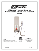
Lift Operator - The unit controls all lift operations identical to
the user hand set. Three cables connect to the bottom of the
Control Box to enable operation of the lift. The largest
connector is for the hand control. Connector # 1 is for the
motor cable (red stripe). Connector # 2 is for the actuator cable
(green stripe). The LiftOperator® is available with an optional
Activation Key feature that provides a higher level of security
by allowing control operation only with the use of the activation
key. Touchpad Control –
The touchpad control arrow keys can be used in the
event that the hand control is out of reach or fails.
Simply press and hold the arrow for the desired action
for one movement at a time – Up, Down, Left, Right
Releasing the Arrow stops movement.
Battery Level LED Indicators –
The Battery Level LED Indicators show battery charge levels. The LED’s will illuminate when
either the touchpad control or the hand control is activated and will stay lit for 10 seconds. At
greater than 50% the LED glows Green, at less than 50% the LED glows Amber, and less than
25% the LED glows red and indicates the battery requires charging. If the less than 25% LED
glows red, do not operate the lift. Remove the battery and fully charge before use.
Service Required LED –
The Service Required LED will illuminate when the battery pack has been removed/replaced 120
times - approximately once every 4 months. This indicates that required maintenance for the lift
must be completed. Please see the maintenance section of the Lift Owner’s Manual for the
requirements. The Service Required LED can be reset by inserting a standard FAT-formatted
USB mass storage device (not included) into the USB Port on the bottom of the controller. When
CONNECTOR 1
(MOTOR CABLE)
CONNECTOR 2
(ACTUATOR CABLE)

8
the service light is illuminated the lift must not be used until required maintenance is
performed.
Emergency Stop Button –
In the event of an emergency, or if you need to stop lift movement immediately, pressing the
Emergency Stop Button (red button on the control) will stop all lift movement. At the same time an
audible alert will sound for 10 sec. then pause for 5 sec. and then the sequence will repeat until
the button is reset by turning it in the direction of the arrows on the button (clockwise). The
Emergency Alert LED will also flash Red when the button is pressed and will remain flashing until
the button is reset.
The Emergency Alert (audible and LED) can be activated by pressing any two buttons on the
hand control at the same time (provided with the lift). This will stop all lift movement and activate
the audible alert and the Red LED will flash. Once both buttons are released, the lift will return to
normal operation and the emergency audible alert will silence.
USB Port –
The LiftOperator® control contains a USB port that is used to download the performance log of
the lift. Using any standard FAT file formatted USB memory stick (widely available through retail
outlets) insert the stick into the slot on the bottom of the control on the far right hand side. Press
any of the touchpad control arrows; all three of the Battery Level LED’s will flash. During
downloading the Green greater than 50% Battery Level LED will flash. If the unit has a problem
downloading the performance log the Red less than 25% LED will flash. Remove the USB from
the port and re-insert it. If the Red 25% LED flashes again, confirm that the USB you are using is
FAT file formatted. The information from the USB can be downloaded to a PC for review and/or
copied to a spread sheet. The performance log will retain approximately 7,600 events. Once the
file is full it will remove the oldest event and replace with the newest.
After the summary data, the events are shown with the oldest first. The first column is the time in
seconds from that last event. The second column is the text describing the event. The third
column is duration of the activity noted in seconds.
An example of a short log file:
Activity Description
dev_id_upper,0 Programing data
dev_id_lower,1 Programing data
fw_rev,90 Firmware rev.
batt_volt_float,24929 Non-loaded battery voltage in millivolts
batt_volt_load,21487 Loaded battery voltage in millivolts
batt_capacity,99 Estimated battery capacity in %
charge_starts,8 Number of times charging was attempted
charge_completes,1 Number of times charging was finished successfully
0,power_on,1 Connecting Battery Pack
2,alert_pressed, Emergency Button pressed
3,alert_released, Emergency Button released
8,lift_up,2 Lift movement - up
5,lift_down,2 Lift movement - down
11,lift_up,2
4,turn_left,2 Lift movement - turn left
3,turn_right,1 Lift movement - turn right
3,log_write, USB File Download

9
Battery Pack - The battery pack is located on top of the Control Box and is removable.
To remove - pull the battery pack away from the mounting plate so that the latch on the battery
pack clears the side tabs on the mounting plate - then lift the battery pack up and away from the
Control Box.
To replace - align the battery pack with the mounting plate so that the latch will drop over the
center tab and that the bottom of the battery pack will fit in the recessed area on top of the Control
Box. Lower the battery pack in place so that the latch is fully captured by the mounting plate and
the battery pack drops fully seated onto the Control Box.
The battery must be completely removed from the lift and located away from the pool deck for
charging.
The battery pack should be charged daily. Do not allow battery to fully
discharge, as it will shorten battery life.
The battery pack has an LED indicator near the plug-in-port. It will glow
Red when first plugged into the transformer. If the LED remains Red
this indicates the battery pack needs charging. When fully charged the
LED will glow Green. If the battery is fully charged and is plugged into
the transformer the LED will glow Red for approximately 10 sec. then
glow Green. If the LED flashes Red when plugged in this indicates a
fault with the battery and indicates the battery pack should be
replaced. All batteries are inspected prior to shipment. See warranty
policy regarding battery replacement for problems after sale. Batteries
have a normal lifespan of between 2-3 years, depending on use and
care. A fully charged battery will provide approximately 30 to 40-lifting
cycles, depending on the weight of the users. Prior to use the battery charge level should be checked by
observing the LED indicator above the charger plug to ensure sufficient charge level. The charger must
be connected to the battery to view the LED.
It is not necessary to fully discharge the battery prior to charging. Battery should be charged daily and
cannot be overcharged. It takes up to twelve hours to fully charge depending upon battery usage. Do not
allow battery to fully discharge, as it will shorten battery life.
Do not drop the battery, as it could cause the unit to fail. If the battery case is cracked do not use and
replace the battery. During temperature extremes beyond the range of 41 F (5 C) to 104 F (40 C) remove
battery and place in a controlled environment or battery life may be shortened.

10
Battery Disposal - The batteries located inside the battery pack are recyclable and shall be disposed of
in accordance with applicable local, state/provincial or federal/national regulations.
Locking Plate Assembly - The battery pack can be secured to the mounting plate using the provided
lock plate assembly. To install open the lock plate so that the bottom tabs are moved close to one another
to allow the lock plate to be inserted into the slots on the mounting plate secured to the lift. Close the lock
plate assembly so that the tabs are captured by the slots. Insert a padlock (not provided) through the
holes on the lock plate assembly to secure it.
Hand Control - The four button unit controls all lift movements. The arrows
indicate direction of movement. Control is fully waterproof and meets IP67
standards.
Mast - This vertical piece is bolted to the base assembly.
Actuator - Attached to mast, it powers the lift’s up and down movements.
Rotation Motor Assembly - Mounting plate, 24-volt motor, and small gear.
Hub Assembly - Hub, bearings, shaft, large gear and mast mounting plate.
Horizontal Support Arms - These two support arms connect the mast to the
seat support arm. The longer horizontal support arm (actuator arm) connects
to the actuator and initiates lifting movements.
Seat Arm - Connects the seat to the horizontal support arms.
Seating System – The seat is manufactured from roto-molded plastic with a stainless steel frame. The
seat comes standard with a seatbelt. The seatbelt must be used during each use. It is recommended that
the seat be rinsed off with fresh water between each use and cleansed daily with a disinfectant solution of
1:100 dilution of household bleach to fresh water and then rinsed with fresh water. In the event of a
contamination incident such as patient/user excreta - cleanse seat and seatbelt immediately with the
above disinfectant solution. Do not use seatbelt if it is damaged or becomes worn.
Armrests are included as a standard item on all S.R. Smith lifts. The armrests are designed so they can
be rotated up out of the way during transfer.
This lift seat assembly is designed to be used exclusively with S.R. Smith aquatic access lifts.
UNPACKING & ASSEMBLY INSTRUCTIONS
REFER TO DIAGRAM (page 23) FOR PARTS IDENTIFICATION.
4-Button Hand
Control

11
READ THESE INSTRUCTIONS IN THEIR ENTIRETY BEFORE UNCRATING PAL2
Prior to opening pallet, inspect external condition for any visible damage. It is important that any
damage be noted on the Bill of Lading. Immediately notify S.R. Smith or your Authorized Reseller
of missing or damaged parts.
The PAL2 is shipped on a covered pallet and is VERY HEAVY. You will need the following tools for
unpacking and assembly:
• 3/4” or 19mm socket wrench
• 9/16” or 14mm socket and 9/16” or 14mm wrench
• small flat blade screwdriver
• knife or cutters to cut shrink-wrap/bands
• claw hammer
Unpacking & Assembly Procedure for the PAL2
1. Cut open enclosure bag at base of unit - carefully remove plastic.
2. Cut internal bands – remove mast assembly, seat assembly and housing. Lift assembly by mast
and seat arm. Do not lift mast assembly by actuator as this could damage the actuator.
3. Remove accessory box.
4. Remove the PAL2 handle from the frame.
5. Roll the main frame from the pallet, across the top of the concrete weights. Position main frame
close to pallet and lock both rear casters.
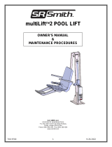
6. Counterweights and Weight restraint belts.
The concrete weights for the lift are located in the bottom of the pallet. Using the claw hammer, remove
the wood restraints to gain access to the blocks. In the accessory carton are the two black belts used for
restraining the weights. Follow the images below to properly install the belts and concrete blocks.
Each concrete weight is approximately 33 lbs /13.6 kg.
Weights leave the factory in good condition; however, they may have shifted during shipping. Inspect the
weights prior to installation to be sure there are no cracked or broken blocks. DO NOT USE DAMAGED
WEIGHTS. Contact S.R. Smith at (800) 824-4387 or customercare@srsmith.com for replacement.
Use caution when lifting the weights, until they are in their final position, mishandling can crack or break
the weight.
IMAGE 1 IMAGE 2
Lace the belts through the frame, as shown in Image 1. Place the outer most blocks in position, as shown
in Image 2 and pull the slack out of the restraint belts.

12
IMAGE 3 IMAGE 4
Image 3 shows the first layer of concrete weights installed. Image 4 shows how to properly stack the last
two layers of concrete weights, using all 24 blocks. Close all gaps between the top layers, ensure they
are all touching and pressed firmly together before tightening the weight straps.
IMAGE 5
Tighten both straps as shown in Image 5 across the top of both rows of weights. Loop the strap through
its buckle and pull firmly securing each top row of weights.
CAUTION: The restraining harnesses must be correctly installed. Failure to correctly attach the
restraining harness to frame may result in the weights shifting during use.
7. Place housing on frame. Ensure the housing fits square and flush to the frame. If necessary, re-
adjust the concrete blocks to address any interference with the housing cover.
8. Remove the two lock nuts and washers from mast mounting hub on base assembly (as shown
below).
9. Position mast assembly through housing and attach to studs located on base assembly with lock
nuts and washers. Fully tighten with 3/4” or 19mm socket wrench.

13
10. Remove plastic from the mast assembly. Remove 3/8”(10mm) bolt and nut from the end of the
actuator arm. Following the illustration below, attach actuator end to end of actuator arm using
the 3/8”(10mm) bolt and nut. Fully tighten bolt and nut using 9/16”(14mm) socket and wrench.
11. The accessory carton contains the control box. Remove the control box and separate the T-20
Star wrench and the small torx screw from the control box.
12. Attach the control as illustrated on the following page.

14
13. Remove the battery from the accessory carton and carefully attach to controller.
14. Insert actuator cable (green label) into connector #2 on the Control Box. Make sure the plug is
secure and fully seated.
15. The 24V motor cable will be secured to the mast in step 18. For the moment, simply string it
through the housing mast hole. Plug the 24V motor cable (red stripe) into connector #1 on the
Control Box. Make sure the plug is secure and completely seated. Allow the 24V motor cable to
hang freely and untangled from the first pre-installed clip.
16. Remove the hand control from the accessory carton. Insert plug into large connector on the
Control Box aligning the key way of the plug.
17. With the battery connected and the 24V Motor plugged in. Rotate the lift using the right arrow so
that the white plastic wire clips attached to the mast face forward. Next, unplug the 24V motor
cord from the controller.
18. To secure the motor cord, follow the steps in
the figures on the following page -
24V MOTOR
HAND CONTROL
ACTUATOR

15
A: Clip the wire into the lower mast clip
B: Lightly tension the wire and clip it into the higher mast clip.
C: Make sure there are no tangles. Then plug the 24V Motor into place.
19. Check up and down controls for proper operation - both touch pad and hand controls.
20. Check left and right controls for proper operation - both touch pad and hand controls.
21. Check Emergency Stop button for operation/activation of internal sounder.

16
22. Remove battery and charge it fully before use.
23. Fully extend both stabilizer bars and fully lock both rear wheels to prevent movement.
24. Attach seat assembly with bolt and thumbnut in appropriate hole. For storage, seat can be
attached facing inward for less space.
25. Attach footrest to seat with bolts and thumbnuts.
USING THE PAL2
Obey all User Instructions listed in this manual whenever using lift. Obey all Caution, Warning,
Operating Instruction(s) and Labels located on the lift whenever using. It is the responsibility of
the lift Owner to ensure that the correct safety procedures have been put in place and a risk
assessment carried out. If a User is mentally challenged or has severe physical disabilities these
issues must be taken into account to determine the number of persons required to complete the
transfer onto the seat and the number of persons required to be in the water, ready to receive the
User. If the PAL2 will be used by a disabled person living on their own, a communication device
should be installed in the area of use to call for assistance in the event of an emergency. Only
persons healthy enough for water activities should use the PAL2. Users should consult with their
physician to determine if water activities are appropriate for the User. Keep fingers and hands
clear of lift arms during use.

17
POSITIONING
Important things to remember when positioning the PAL2 for use:
1. Maintain a firm grip on the handle - use care when positioning the PAL2. It is heavy (1060 lb/ 481 kg).
Only the handle should be used to position the lift. Do not use the seat as a hand hold to move the
PAL2.
2. Position the PAL2 on level ground not to exceed a slope of 2º and in an area that allows for safe
transfer to and from a wheelchair. Consult the ADA guidelines on page 4 for more detailed
information.
3. Fully extend both stabilizing arms.
4. Lock both rear wheels.
WARNING: Failure to fully extend both stabilizing arms and to lock both rear wheels could cause
lift movement during transfer and could result in injury. Both stabilizing arms must be fully
extended and both rear wheels must be locked whenever lift is used. Do not retract stabilizing
arms or unlock rear wheels during transfer as the lift could move and may result in injury. The
maximum lift capacity is 300 lb/136 kg. Keep fingers clear of lift arms during use.
PAL2 Positioning Diagram

18
TRANSFERRING
Once the unit is positioned for use with both stabilizing arms fully extended and both rear wheels
locked - use the following procedure to transfer to the seat and into the water. Only persons healthy
enough for water activities should use the PAL2. Users should consult with their physician to determine if
water activities are appropriate for the User:
• Keep fingers and hands clear of lift arms during use.
• Rotate seat to either side of the lift for the ideal transfer position.
• Raise or lower seat to ideal transfer height.
• Transfer onto seat, ensuring user’s weight is centered on seat. Armrests can be rotated up if
necessary (optional US/standard on export). If user has a wheelchair, keep chair close by for
easy retrieval.
• Fasten Seat Belt - thread loose end of belt strap through buckle - pull tight - to close - press latch
down on belt material.
• Raise seat to allow enough legroom for rotation.
• Rotate seat to the 12 o’clock position, over water.
• Lower seat into pool. The waterproof hand control can remain connected to seat if swimmer is
operating lift.
• Unfasten Seat Belt - grasp latch and lift up, pull loose end from latch.
• When finished, return to seat, ensuring user’s weight is centered on seat.
• Raise seat to allow enough legroom for rotation.
• Rotate seat to original transfer position.
• Raise or lower seat to proper transfer height.
• Unfasten Seat Belt.
• Transfer off of seat.
WARNING: The PAL2 lift is designed to transfer users from the deck surrounding the swimming
pool/spa into the water and back again. It is not designed to transport users from place to place.
Serious injury can result if the lift is moved while a user is in the seat.
IN CASE OF HAND CONTROL FAILURE
Lifting failure - In the event of a lifting failure, there are control buttons built into the control box. Press
the appropriate up or down/ left or right button located on the front panel of the control box.
If the PAL2 will be used by a disabled person living on their own, a communication device should
be installed in the area of use to call for assistance in the event of an emergency.
IN CASE OF BATTERY FAILURE
Turning failure - If the lift will not turn electronically, you can remove the housing and loosen the nut
(7/16” – 11mm) on the tension spring located next to the turning motor. This will disengage the gears and
allow the lift to be turned manually.
If the PAL2 will be used by a disabled person living on their own, a communication device should
be installed in the area of use to call for assistance in the event of an emergency.
STANDARD ACCESSORIES/OPTIONAL ACCESSORIES
The following items are included with all pool lift models:
• Seat Belt Assembly – Nylon water-resistant belt for added security.
• Battery/Charger – 24-volt rechargeable battery.
• Console/Battery Cover – Protects battery and control unit from exposure to UV and moisture.

19
Optional accessories may be purchased for your PAL2 – through your Authorized Reseller. The following
accessories are available:
Deck Cover PAL2 - # 920-5000: Made of weather resistant nylon material to keep unit protected from
elements when not in use.
Spine Board Attachment - # 500-1000: Can be used to convert lift for use with any standard spine
board. (Spine Board not included)
PAL Secure-it Kit- # 200-1090A: Used to secure lift in place on deck.
MAINTENANCE and CLEANSING
Minimal maintenance will prolong the life of your lift. Keep all electronic components clean and dry. Keep
the Console/Battery Cover installed at all times to prevent moisture from collecting on the Control Box
and battery. Excessive moisture collection can affect battery and lift performance and could lead to
battery failure and/or the lift failing to operate. If the lift is used outdoors, an optional full cover is available
and recommended.
Owners of lifts shall be aware of any applicable local, state/provincial or federal/national regulations
regarding the inspection and or testing of lifts.
The following schedule must be performed to insure proper operation with the Daily items
performed before each use:
Maintenance Performed
Daily
Weekly
Monthly
Check battery level before each use / Charge battery daily
Wipe Control Box and battery connection with a clean dry rag
Examine lift for any damage, loose or missing hardware
Test for normal operation
Spray gear assembly with a heavy-duty rust inhibitor/lubricant
such as LPS 3 - Heavy-Duty Inhibitor
Make sure all cable connections are properly secured
Inspect lift frame, mast, support arm and seat assembly for rust
Inspect weight stack for rust/treat with touch up paint
Cleansing Performed – after each use
Rinse seat and seatbelt with fresh water between each use -
Cleanse seat and seatbelt with a disinfectant solution of 1:100
dilution of household bleach to fresh water and then rinse with
fresh water and dry entire lift daily. In the event of a
contamination incident such patient/user excreta - cleanse seat
and seatbelt immediately with the disinfectant solution*
Cleanse all battery connections with a nylon scouring pad
Cleanse all metallic surfaces with a cleaner wax to maintain the
finish of the lift
* When using the disinfection solution avoid direct contact with the skin and eyes. In the event of a
contamination incident - immerse the seat belt in the disinfection solution for 10 min. and then rinse
thoroughly with fresh water.

20
TROUBLE SHOOTING
Visit srsmith.com/en-us/customer-service/lift-troubleshooting to view our library of pool lift
maintenance and troubleshooting videos.
Be sure the battery is fully charged before troubleshooting.
Lift does not rotate
Does lift raise or lower?
Yes.
1. Check connection to Control Box. Be sure plug is pushed in all the way.
2. Check hand control connection to Control Box for damaged pins.
3. Check connections on terminal block located on frame for loose wires.
4. Check connection cable for damage.
5. Try operating the lift using the control buttons on the front panel of the controller. If
the lift rotates when using the buttons on the control box, the hand control is likely the
problem.
6. If the lift does not rotate when using the buttons on the control box, reverse the motor
cables as follows: Locate the area on the Control Box where the cables are attached.
Swap the actuator cable from connector #2 and the 24V motor cable from connector
#1. Activate the up and down buttons on the hand control. If lift rotates, the problem
is likely the hand control. If lift does not rotate, the problem is likely the 24V motor.
7. Contact your Authorized Reseller or S.R. Smith for component replacement
information.
Does lift raise or lower?
No.
1. Check battery charge level.
2. Check battery connection.
3. Use another fully charged battery. If lift continues to not function, replace the Control
Box.
Lift does not Raise or Lower
Does lift rotate?
Yes.
1. Check connection to Control Box. Be sure plug is pushed in all the way.
2. Check hand control connection to Control Box for damaged pins.
3. Check connection cable for damage.
4. Activate the up and down buttons on the front panel of the control box. If lift raises
and lowers, the problem is likely the hand control.
5. If lift does not raise and lower when using the buttons on the control box, reverse the
motor cables as follows: Locate the area on the Control Box where the cables are
attached. Swap the actuator cable from connector #2 and the 24V motor cable from
connector #1. Activate the left and right buttons on the hand control. If lift raises and
lowers, the problem is likely the hand control. If lift does not raise and lower, the
problem is likely the Actuator.
6. Contact your Authorized Reseller or S.R. Smith for component replacement
information.
Does lift rotate?
No.
1. Check battery charge level.
2. Check battery connection.
3. Use another fully charged battery. If lift does not function, replace the Control Box.
/